

Hangcha X 1,0–3,8 т: Service Manual 2025
Англоязычное сервисное руководство для погрузчиков X с ДВС грузоподъёмностью 1,0–3,8 т.
- Модели и серия
- X series Internal Combustion Counterbalanced Forklift Truck 1.0t–3.8t
- Язык документа
- Английский
- Назначение документа
- Сервисное руководство · 02/2025
Для какой техники этот документ
В документе описаны X series Internal Combustion Counterbalanced Forklift Truck 1.0t–3.8t. Полный индекс на заводской табличке должен соответствовать перечню руководства. Для вашей машины используйте документацию нужной редакции и комплектации. Редакция руководства: 02/2025.
Читать полную инструкциюДокумент целиком
Скачать PDF Полный текст инструкции
Страница 1
SERVICE MANUAL
HANGCHA GROUP CO., LTD.
02/2025
X series
Internal Combustion Counterbalanced
Forklift Truck 1.0t-3.8t
Оригинальная страница: таблицы и схемы
Страница 2
Foreword
The manual is the introduction of structure, working principle and serving of 1t-3.8t X
series internal combustion counterbalance forklift truck.
For safety and performance of truck, all in charge of operation, maintenance and
management must read and comprehend this manual well.
The manual also applies to container fork-lift trucks.
It is forbidden anybody without training and qualification to maintain.
Our product design will update and perform better, so the content in this manual may
be not the same as the forklift you owned.
If you have any questions please keep touches with HANGCHA GROUP CO., LTD. sales
department or let the agents know.
© 02/2025 HANGCHA GROUP CO., LTD.
Оригинальная страница: таблицы и схемы
Страница 3
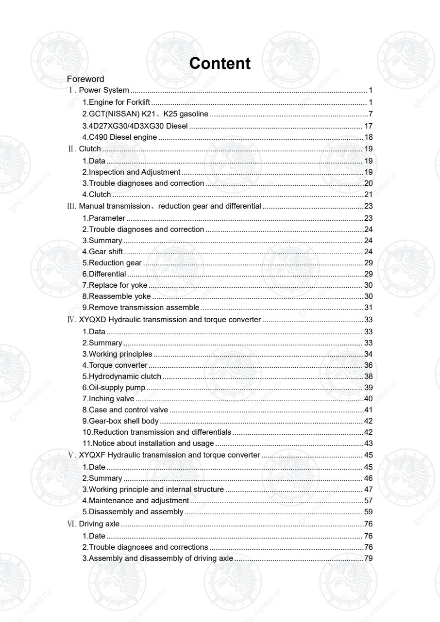
Content
Foreword
Ⅰ. Power System ................................................................................................................ 1
1.Engine for Forklift...................................................................................................... 1
2.GCT(NISSAN) K21、K25 gasoline ...........................................................................7
3.4D27XG30/4D3XG30 Diesel .................................................................................. 17
4.C490 Diesel engine .................................................................................................18
Ⅱ. Clutch ........................................................................................................................... 19
1.Data......................................................................................................................... 19
2.Inspection and Adjustment ......................................................................................19
3.Trouble diagnoses and correction ...........................................................................20
4.Clutch .......................................................................................................................21
Ⅲ. Manual transmission、reduction gear and differential ................................................23
1.Parameter................................................................................................................23
2.Trouble diagnoses and correction ...........................................................................24
3.Summary ................................................................................................................. 24
4.Gear shift................................................................................................................. 24
5.Reduction gear ........................................................................................................ 29
6.Differential................................................................................................................29
7.Replace for yoke ..................................................................................................... 30
8.Reassemble yoke ....................................................................................................30
9.Remove transmission assemble .............................................................................31
Ⅳ. XYQXD Hydraulic transmission and torque converter................................................33
1.Data......................................................................................................................... 33
2.Summary ................................................................................................................. 33
3.Working principles ................................................................................................... 34
4.Torque converter..................................................................................................... 36
5.Hydrodynamic clutch ...............................................................................................38
6.Oil-supply pump...................................................................................................... 39
7.Inching valve ............................................................................................................40
8.Case and control valve ............................................................................................41
9.Gear-box shell body ................................................................................................ 42
10.Reduction transmission and differentials ..............................................................42
11.Notice about installation and usage ......................................................................43
Ⅴ. XYQXF Hydraulic transmission and torque converter ................................................ 45
1.Date......................................................................................................................... 45
2.Summary ................................................................................................................. 46
3.Working principle and internal structure ................................................................. 47
4.Maintenance and adjustment..................................................................................57
5.Disassembly and assembly .................................................................................... 59
Ⅵ. Driving axle ...................................................................................................................76
1.Date......................................................................................................................... 76
2.Trouble diagnoses and corrections .........................................................................76
3.Assembly and disassembly of driving axle .............................................................79
Оригинальная страница: таблицы и схемы
Страница 4
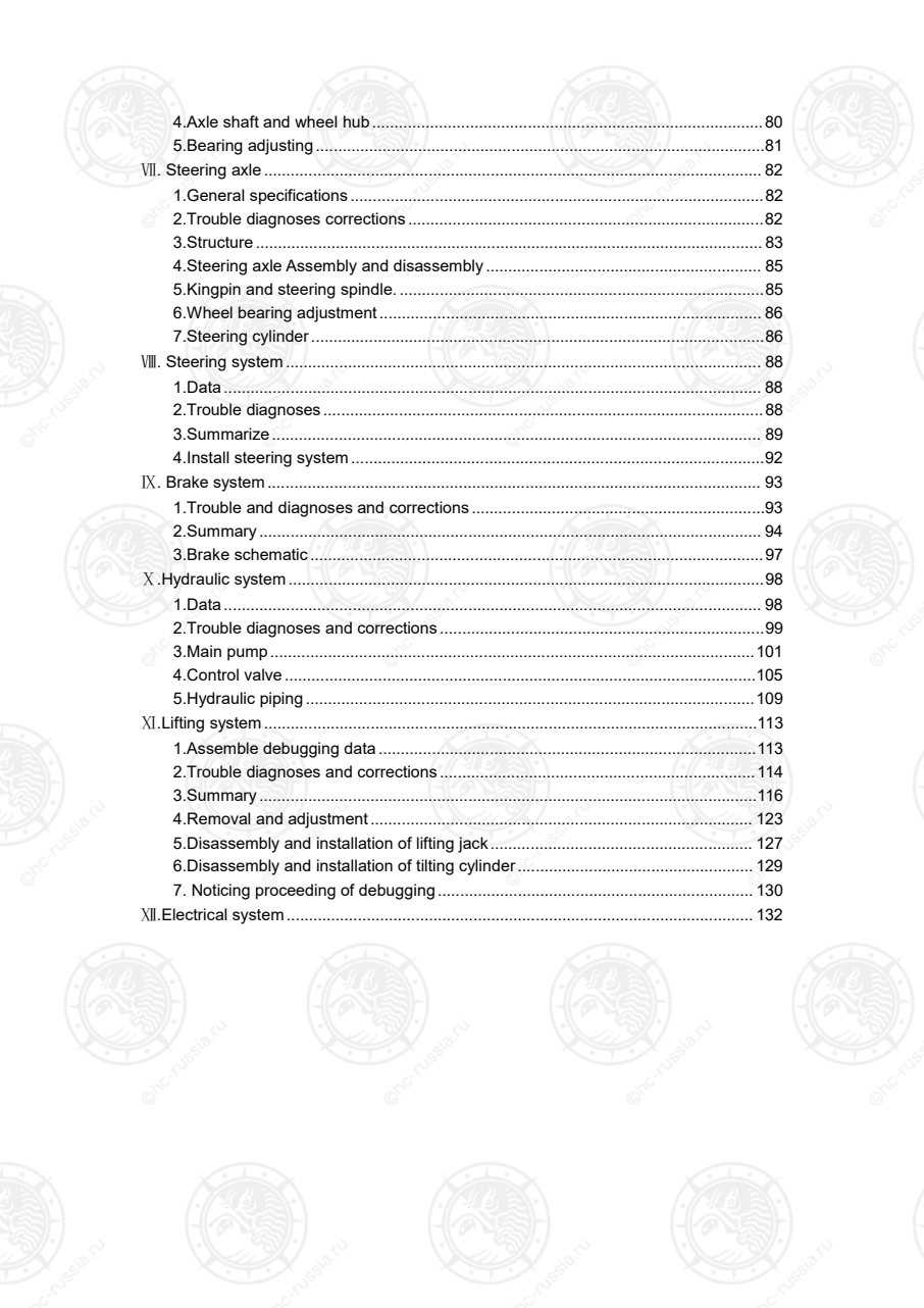
4.Axle shaft and wheel hub........................................................................................80
5.Bearing adjusting .....................................................................................................81
Ⅶ. Steering axle ................................................................................................................ 82
1.General specifications .............................................................................................82
2.Trouble diagnoses corrections ................................................................................82
3.Structure .................................................................................................................. 83
4.Steering axle Assembly and disassembly .............................................................. 85
5.Kingpin and steering spindle. ..................................................................................85
6.Wheel bearing adjustment ...................................................................................... 86
7.Steering cylinder......................................................................................................86
Ⅷ. Steering system ........................................................................................................... 88
1.Data......................................................................................................................... 88
2.Trouble diagnoses ...................................................................................................88
3.Summarize .............................................................................................................. 89
4.Install steering system .............................................................................................92
Ⅸ. Brake system ............................................................................................................... 93
1.Trouble and diagnoses and corrections ..................................................................93
2.Summary ................................................................................................................. 94
3.Brake schematic......................................................................................................97
Ⅹ.Hydraulic system ...........................................................................................................98
1.Data......................................................................................................................... 98
2.Trouble diagnoses and corrections .........................................................................99
3.Main pump.............................................................................................................101
4.Control valve ..........................................................................................................105
5.Hydraulic piping .....................................................................................................109
Ⅺ.Lifting system ...............................................................................................................113
1.Assemble debugging data .....................................................................................113
2.Trouble diagnoses and corrections .......................................................................114
3.Summary ................................................................................................................116
4.Removal and adjustment ...................................................................................... 123
5.Disassembly and installation of lifting jack........................................................... 127
6.Disassembly and installation of tilting cylinder..................................................... 129
7. Noticing proceeding of debugging ....................................................................... 130
Ⅻ.Electrical system ......................................................................................................... 132
Оригинальная страница: таблицы и схемы
Страница 5
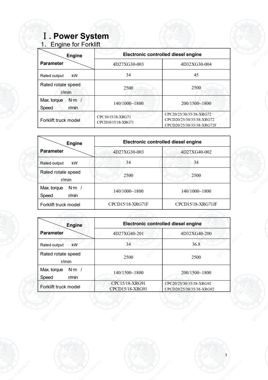
1
Ⅰ. Power System
1.Engine for Forklift
Engine
Parameter
Electronic controlled diesel engine
4D27XG30-003 4D32XG30-004
Rated output kW 34 45
Rated rotate speed
r/min
2500 2500
Max. torque N·m /
Speed r/min
140/1000~1800 200/1500~1800
Forklift truck model
CPC10/15/18-XRG71
CPCD10/15/18-XRG71
CPC20/25/30/35/38-XRG72
CPCD20/25/30/35/38-XRG72
CPCD20/25/30/35/38-XRG72F
Engine
Parameter
Electronic controlled diesel engine
4D27XG30-003 4D27XG40-002
Rated output kW 34 34
Rated rotate speed
r/min
2500 2500
Max. torque N·m /
Speed r/min
140/1000~1800 140/1000~1800
Forklift truck model CPCD15/18-XRG71F CPCD15/18-XRG71JF
Engine
Parameter
Electronic controlled diesel engine
4D27XG40-201 4D32XG40-200
Rated output kW 34 36.8
Rated rotate speed
r/min
2500 2500
Max. torque N·m /
Speed r/min
140/1500~1800 200/1500~1800
Forklift truck model CPC15/18-XRG91
CPCD15/18-XRG91
CPC20/25/30/35/38-XRG92
CPCD20/25/30/35/38-XRG92
Оригинальная страница: таблицы и схемы
Страница 6
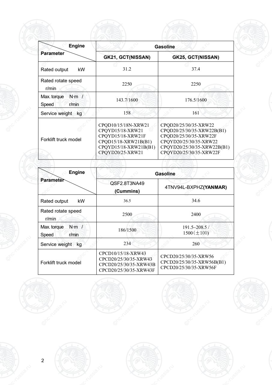
2
Engine
Parameter
Gasoline
GK21, GCT(NISSAN) GK25, GCT(NISSAN)
Rated output kW 31.2 37.4
Rated rotate speed
r/min
2250 2250
Max. torque N·m /
Speed r/min
143.7/1600 176.5/1600
Service weight kg 158 161
Forklift truck model
CPQD10/15/18N-XRW21
CPQYD15/18-XRW21
CPQYD15/18-XRW21F
CPQD15/18-XRW21B(B1)
CPQYD15/18-XRW21B(B1)
CPQYD20/25-XRW21
CPQD20/25/30/35-XRW22
CPQD20/25/30/35-XRW22B(B1)
CPQD20/25/30/35-XRW22F
CPQYD20/25/30/35-XRW22
CPQYD20/25/30/35-XRW22B(B1)
CPQYD20/25/30/35-XRW22F
Engine
Parameter
Gasoline
QSF2.8T3NA49
(Cummins)
4TNV94L-BXPHZ(YANMAR)
Rated output kW 36.5 34.6
Rated rotate speed
r/min
2500 2400
Max. torque N·m /
Speed r/min
186/1500 191.5~208.5 /
1500(±100)
Service weight kg 234 260
Forklift truck model
CPCD10/15/18-XRW43
CPCD20/25/30/35-XRW43
CPCD20/25/30/35-XRW43B
CPCD20/25/30/35-XRW43F
CPCD20/25/30/35-XRW56
CPCD20/25/30/35-XRW56B(B1)
CPCD20/25/30/35-XRW56F
Оригинальная страница: таблицы и схемы
Страница 7
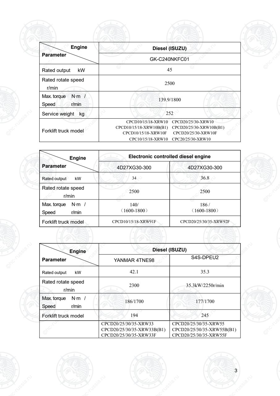
3
Engine
Parameter
Diesel (ISUZU)
GK-C240NKFC01
Rated output kW 45
Rated rotate speed
r/min
2500
Max. torque N·m /
Speed r/min
139.9/1800
Service weight kg 252
Forklift truck model
CPCD10/15/18-XRW10 CPCD20/25/30-XRW10
CPCD10/15/18-XRW10B(B1) CPCD20/25/30-XRW10B(B1)
CPCD10/15/18-XRW10F CPCD20/25/30-XRW10F
CPC10/15/18-XRW10 CPC20/25/30-XRW10
Engine
Parameter
Electronic controlled diesel engine
4D27XG30-300 4D27XG30-300
Rated output kW 34 36.8
Rated rotate speed
r/min
2500 2500
Max. torque N·m /
Speed r/min
140/
(1600-1800)
186 /
(1600-1800)
Forklift truck model CPCD10/15/18-XRW91F CPCD20/25/30/35-XRW92F
Engine
Parameter
Diesel (ISUZU)
YANMAR 4TNE98 S4S-DPEU2
Rated output kW 42.1 35.3
Rated rotate speed
r/min
2300 35.3kW/2250r/min
Max. torque N·m /
Speed r/min
186/1700 177/1700
Forklift truck model 194 245
CPCD20/25/30/35-XRW33
CPCD20/25/30/35-XRW33B(B1)
CPCD20/25/30/35-XRW33F
CPCD20/25/30/35-XRW55
CPCD20/25/30/35-XRW55B(B1)
CPCD20/25/30/35-XRW55F
Оригинальная страница: таблицы и схемы
Страница 8
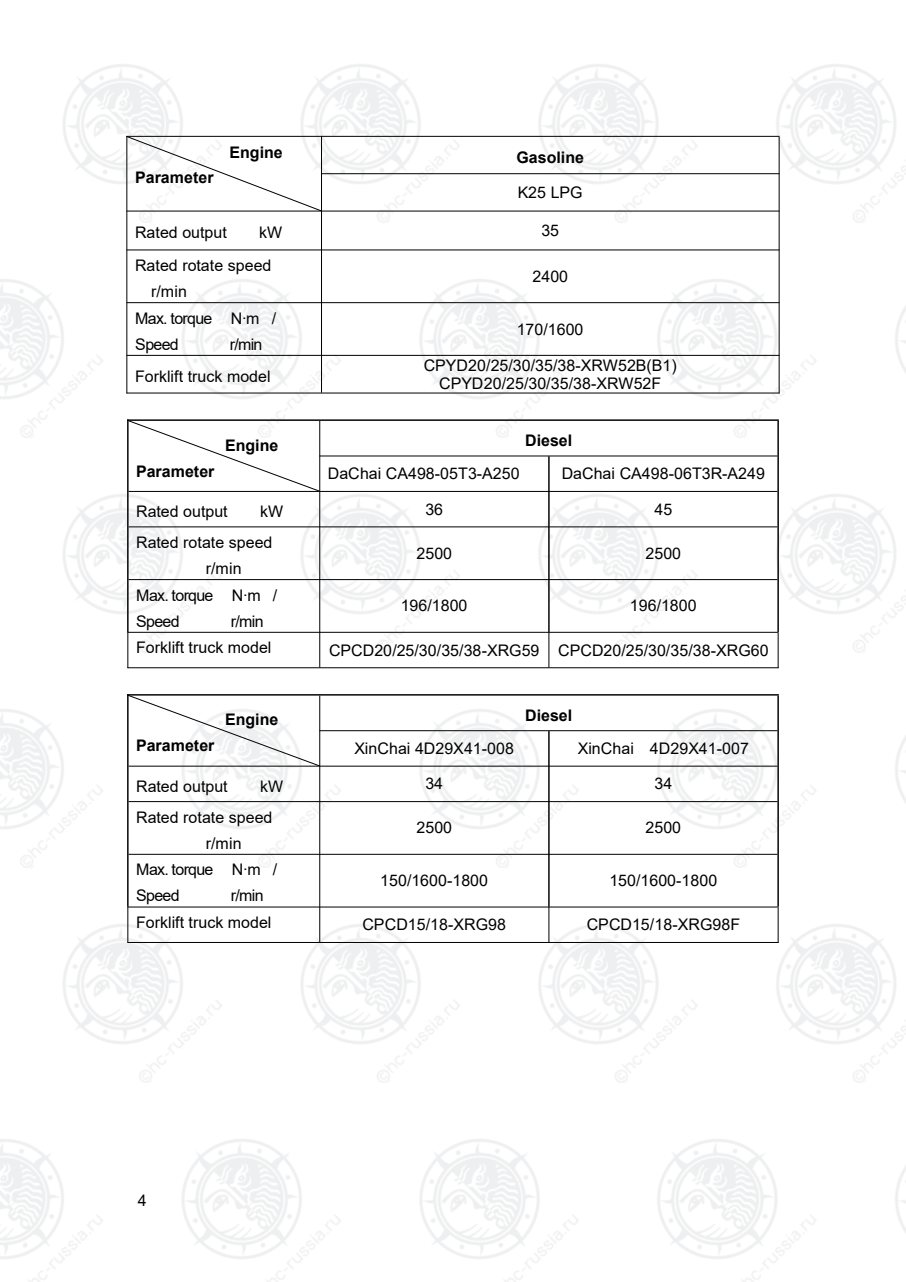
4
Engine
Parameter
Gasoline
K25 LPG
Rated output kW 35
Rated rotate speed
r/min
2400
Max. torque N·m /
Speed r/min
170/1600
Forklift truck model CPYD20/25/30/35/38-XRW52B(B1)
CPYD20/25/30/35/38-XRW52F
Engine
Parameter
Diesel
DaChai CA498-05T3-A250 DaChai CA498-06T3R-A249
Rated output kW 36 45
Rated rotate speed
r/min
2500 2500
Max. torque N·m /
Speed r/min
196/1800 196/1800
Forklift truck model CPCD20/25/30/35/38-XRG59 CPCD20/25/30/35/38-XRG60
Engine
Parameter
Diesel
XinChai 4D29X41-008 XinChai 4D29X41-007
Rated output kW 34 34
Rated rotate speed
r/min
2500 2500
Max. torque N·m /
Speed r/min
150/1600-1800 150/1600-1800
Forklift truck model CPCD15/18-XRG98 CPCD15/18-XRG98F
Оригинальная страница: таблицы и схемы
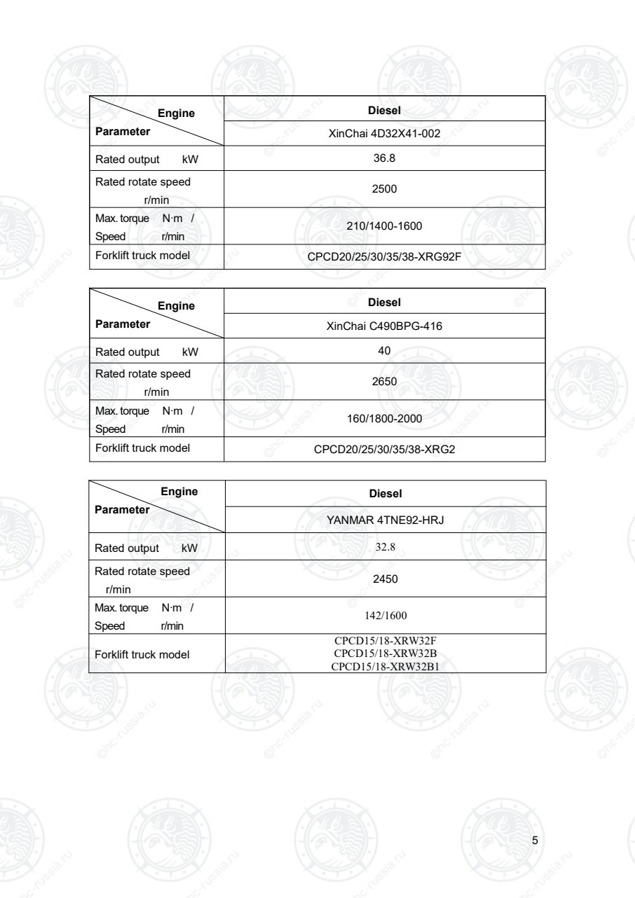
Страница 9
5
Engine
Parameter
Diesel
XinChai 4D32X41-002
Rated output kW 36.8
Rated rotate speed
r/min
2500
Max. torque N·m /
Speed r/min
210/1400-1600
Forklift truck model CPCD20/25/30/35/38-XRG92F
Engine
Parameter
Diesel
XinChai C490BPG-416
Rated output kW 40
Rated rotate speed
r/min
2650
Max. torque N·m /
Speed r/min
160/1800-2000
Forklift truck model CPCD20/25/30/35/38-XRG2
Engine
Parameter
Diesel
YANMAR 4TNE92-HRJ
Rated output kW 32.8
Rated rotate speed
r/min
2450
Max. torque N·m /
Speed r/min
142/1600
Forklift truck model
CPCD15/18-XRW32F
CPCD15/18-XRW32B
CPCD15/18-XRW32B1
Оригинальная страница: таблицы и схемы
Страница 10
6
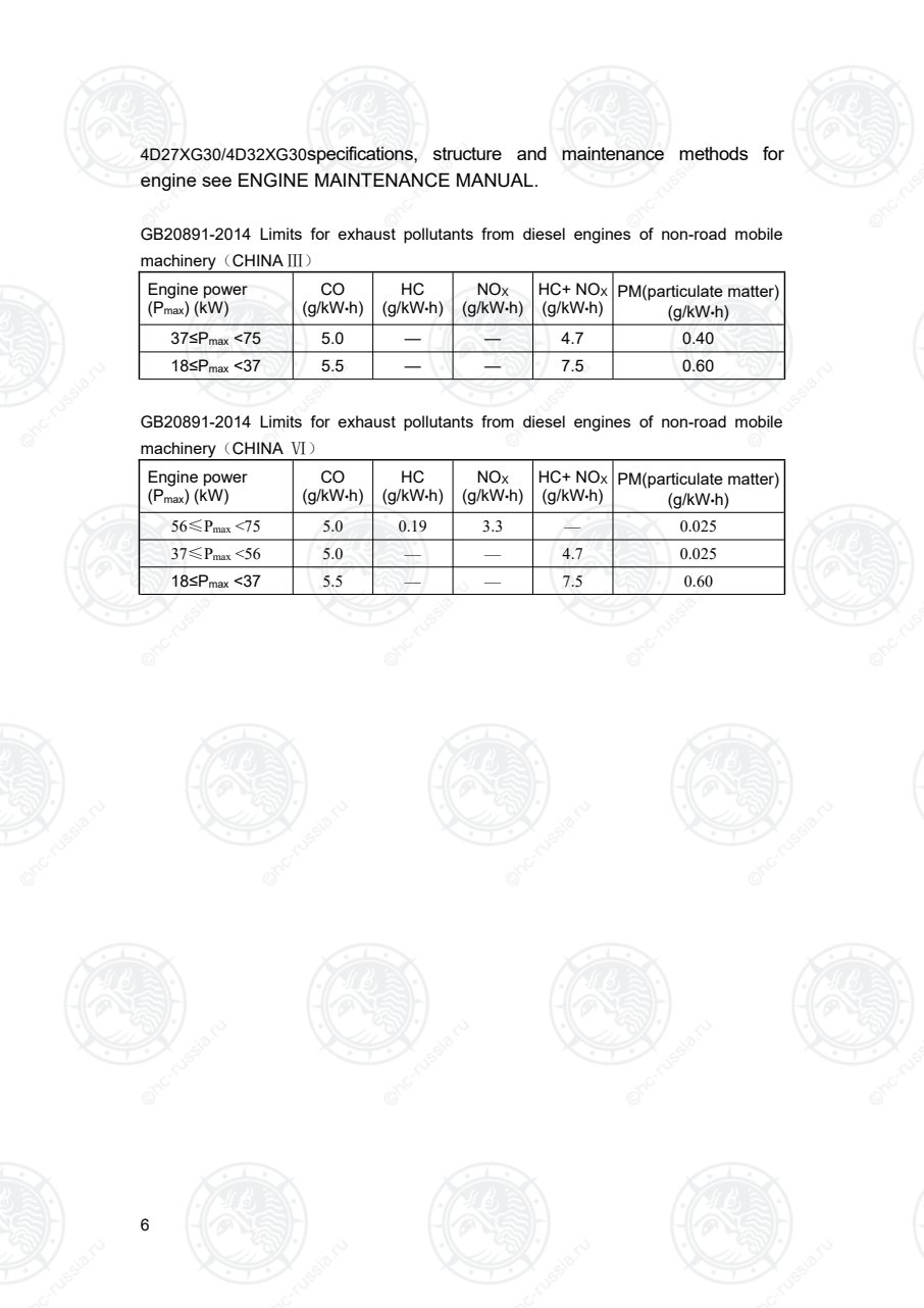
4D27XG30/4D32XG30specifications, structure and maintenance methods for
engine see ENGINE MAINTENANCE MANUAL.
GB20891-2014 Limits for exhaust pollutants from diesel engines of non-road mobile
machinery(CHINAⅢ)
Engine power
(Pmax) (kW)
CO
(g/kW•h)
HC
(g/kW•h)
NOX
(g/kW•h)
HC+ NOX
(g/kW•h)
PM(particulate matter)
(g/kW•h)
37≤Pmax <75 5.0 — — 4.7 0.40
18≤Pmax <37 5.5 — — 7.5 0.60
GB20891-2014 Limits for exhaust pollutants from diesel engines of non-road mobile
machinery(CHINA Ⅵ)
Engine power
(Pmax) (kW)
CO
(g/kW•h)
HC
(g/kW•h)
NOX
(g/kW•h)
HC+ NOX
(g/kW•h)
PM(particulate matter)
(g/kW•h)
56≤Pmax <75 5.0 0.19 3.3 — 0.025
37≤Pmax <56 5.0 — — 4.7 0.025
18≤Pmax <37 5.5 — — 7.5 0.60
Оригинальная страница: таблицы и схемы
Страница 11
7
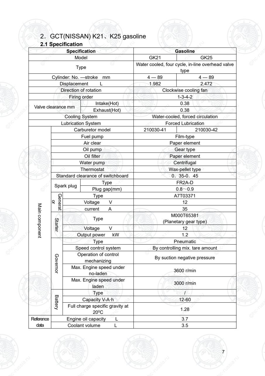
2.GCT(NISSAN) K21、K25 gasoline
2.1 Specification
Specification Gasoline
Model GK21 GK25
Type Water cooled, four cycle, in-line overhead valve
type
Cylinder: No. —stroke mm 4 — 89 4 — 89
Displacement L 1.982 2.472
Direction of rotation Clockwise cooling fan
Firing order 1-3-4-2
Valve clearance mm Intake(Hot) 0.38
Exhaust(Hot) 0.38
Cooling System Water-cooled, forced circulation
Lubrication System Forced Lubrication
Maincomponent
Carburetor model 210030-41 210030-42
Fuel pump Film-type
Air clear Paper element
Oil pump Gear type
Oil filter Paper element
Water pump Centrifugal
Thermostat Wax-pellet type
Standard clearance of switchboard 0.35-0.45
Spark plug Type FR2A-D
Plug gap(mm) 0.8~0.9
Generat
or
Type A7T03371
Voltage V 12
current A 35
Starter
Type M000T65381
(Planetary gear type)
Voltage V 12
Output power kW 1.2
Governor
Type Pneumatic
Speed control system By controlling mix. tare amount
Operation of control
mechanizing By suction negative pressure
Max. Engine speed under
no-laden 3600 r/min
Max. Engine speed under
laden 3000 r/min
Battery
Type /
Capacity V-A·h 12-60
Full charge specific gravity at
200C 1.28
Reference
data
Engine oil capacity L 3.7
Coolant volume L 3.5
Оригинальная страница: таблицы и схемы
Страница 12
8
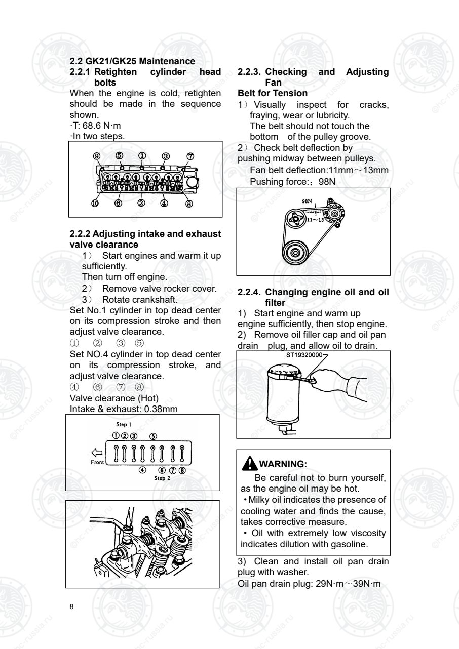
2.2 GK21/GK25 Maintenance
2.2.1 Retighten cylinder head
bolts
When the engine is cold, retighten
should be made in the sequence
shown.
·T: 68.6 N·m
·In two steps.
2.2.2 Adjusting intake and exhaust
valve clearance
1) Start engines and warm it up
sufficiently.
Then turn off engine.
2) Remove valve rocker cover.
3) Rotate crankshaft.
Set No.1 cylinder in top dead center
on its compression stroke and then
adjust valve clearance.
① ② ③ ⑤
Set NO.4 cylinder in top dead center
on its compression stroke, and
adjust valve clearance.
④ ⑥ ⑦ ⑧
Valve clearance (Hot)
Intake & exhaust: 0.38mm
2.2.3. Checking and Adjusting
Fan
Belt for Tension
1) Visually inspect for cracks,
fraying, wear or lubricity.
The belt should not touch the
bottom of the pulley groove.
2) Check belt deflection by
pushing midway between pulleys.
Fan belt deflection:11mm~13mm
Pushing force::98N
2.2.4. Changing engine oil and oil
filter
1) Start engine and warm up
engine sufficiently, then stop engine.
2) Remove oil filler cap and oil pan
drain plug, and allow oil to drain.
WARNING:
Be careful not to burn yourself,
as the engine oil may be hot.
·Milky oil indicates the presence of
cooling water and finds the cause,
takes corrective measure.
· Oil with extremely low viscosity
indicates dilution with gasoline.
3) Clean and install oil pan drain
plug with washer.
Oil pan drain plug: 29N·m~39N·m
Оригинальная страница: таблицы и схемы
Страница 13
9
4) Using tool remove oil filter.
5) Wipe oil filter mounting surface
with a clean rag.
6) Smear a little engine oil on
rubber gasket of new oil filter.
7) Install new oil filter. Hand-tighten
ONLY.
Don’t use a wrench to tighten the
filter.
8) Refill engine with new
recommended engine oil, referring to
Recommended Lubricants.
Check oil level with dipstick.
Oil capacity: 3.6 L。
9) Start engine, check area around
drain plug and oil filter for any sign of
oil leakage.
If any Leakage is evident, these
parts have not been properly
installed.
10) Warm up engine sufficiently.
Then stop engine and wait a few
minutes. Check oil level. If
necessary,
add engine oil.
When checking oil level, park the
forklift on a level surface.
2.2.5. Changing Engine Coolant
△! WARNING:
To avoid the danger of being scalded,
never attempt to change the coolant
when the engine is hot. When using
anti-freeze coolant, mix the
anti-freeze coolant with water.
2.2.6. Cleaning Radiator Outside
Clean outside of radiator with dry
compressed air.
2.2.7. Checking cooling System,
Hoses and Connections.
Check hoses and fittings for Lose
connections or deterioration.
Retighten or replace if necessary.
2.2.8. Checking Engine
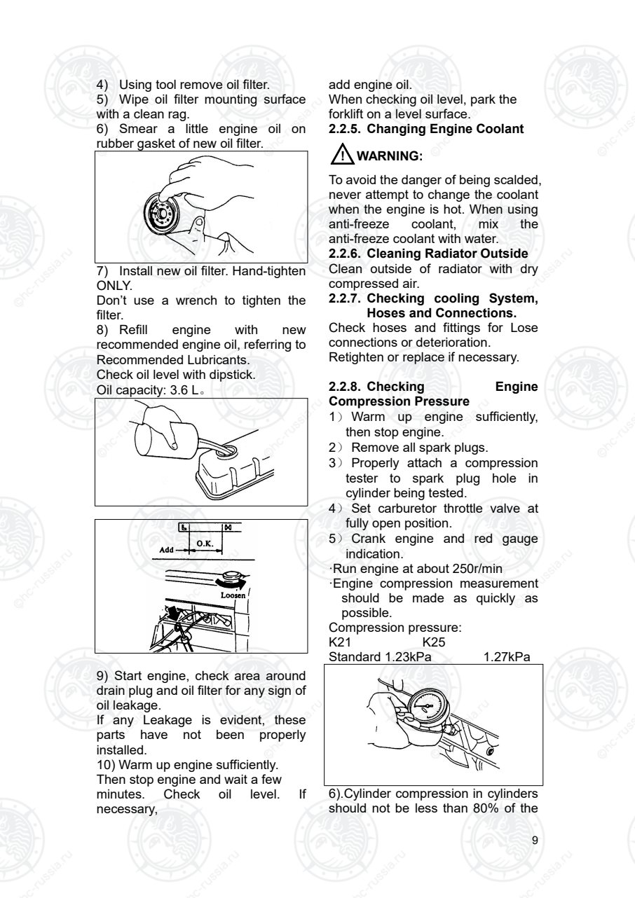
Compression Pressure
1) Warm up engine sufficiently,
then stop engine.
2) Remove all spark plugs.
3) Properly attach a compression
tester to spark plug hole in
cylinder being tested.
4) Set carburetor throttle valve at
fully open position.
5) Crank engine and red gauge
indication.
·Run engine at about 250r/min
·Engine compression measurement
should be made as quickly as
possible.
Compression pressure:
K21 K25
Standard 1.23kPa 1.27kPa
6).Cylinder compression in cylinders
should not be less than 80% of the
Оригинальная страница: таблицы и схемы
Страница 14
10
highest reading.
If cylinder compression in one or
more cylinders is low, pour a small
quantity of engine oil into cylinders
through the spark plug holes and
retest compression.
·If adding oil helps the compression
pressure, piston rings may be worn
or damaged.
·If pressure stays low, valve may be
sticking or seating improperly.
·If cylinder compression in any two
adjacent cylinders is low, and if
adding oil does not help the
compression, there is leakage pass
on the gasket surface.
Oil and water in combustion
chambers can result from this
problem.
2.2.9. Cleaning or Replacing Air
Cleaning Filter (Dry paper type)
It is necessary to clean the
element or replace it at the
recommended interval, and more
frequent maintenance should do in
other dirty operating conditions.
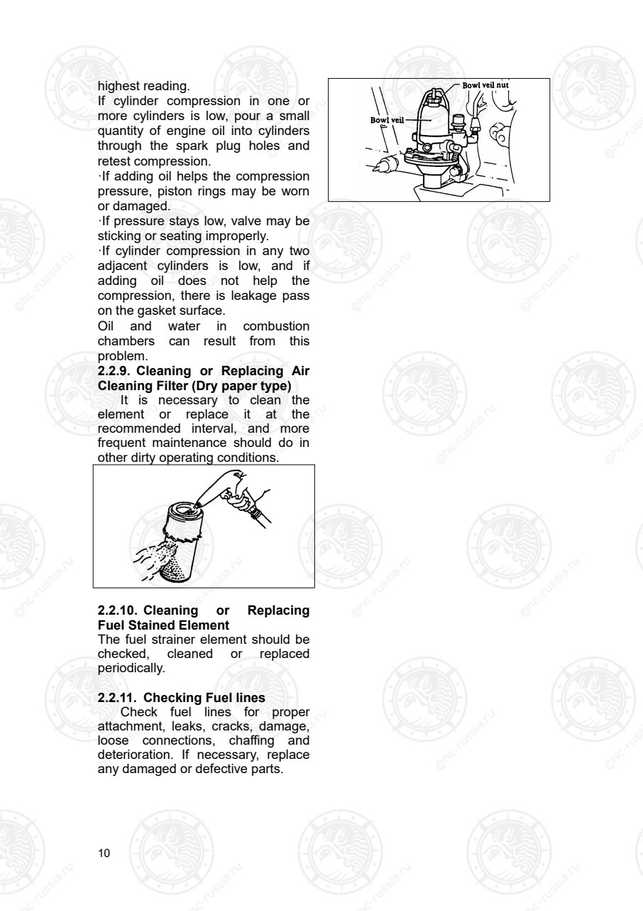
2.2.10. Cleaning or Replacing
Fuel Stained Element
The fuel strainer element should be
checked, cleaned or replaced
periodically.
2.2.11. Checking Fuel lines
Check fuel lines for proper
attachment, leaks, cracks, damage,
loose connections, chaffing and
deterioration. If necessary, replace
any damaged or defective parts.
Оригинальная страница: таблицы и схемы
Страница 15
11
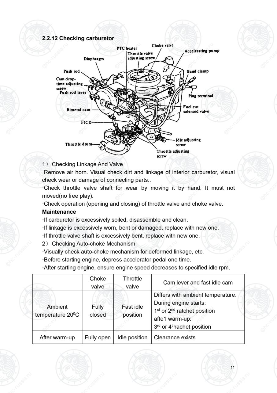
2.2.12 Checking carburetor
1) Checking Linkage And Valve
·Remove air horn. Visual check dirt and linkage of interior carburetor, visual
check wear or damage of connecting parts..
·Check throttle valve shaft for wear by moving it by hand. It must not
moved(no free play).
·Check operation (opening and closing) of throttle valve and choke valve.
Maintenance
·If carburetor is excessively soiled, disassemble and clean.
·If linkage is excessively worn, bent or damaged, replace with new one.
·If throttle valve shaft is excessively bent, replace with new one.
2) Checking Auto-choke Mechanism
·Visually check auto-choke mechanism for deformed linkage, etc.
·Before starting engine, depress accelerator pedal one time.
·After starting engine, ensure engine speed decreases to specified idle rpm.
Choke
valve
Throttle
valve Cam lever and fast idle cam
Ambient
temperature 200C
Fully
closed
Fast idle
position
Differs with ambient temperature.
During engine starts:
1st or 2nd ratchet position
afte1 warm-up:
3rd or 4thrachet position
After warm-up Fully open Idle position Clearance exists
Оригинальная страница: таблицы и схемы
Страница 16
12
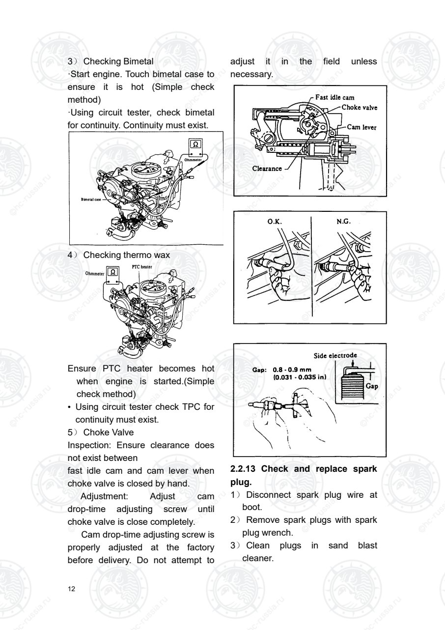
3) Checking Bimetal
·Start engine. Touch bimetal case to
ensure it is hot (Simple check
method)
·Using circuit tester, check bimetal
for continuity. Continuity must exist.
4) Checking thermo wax
Ensure PTC heater becomes hot
when engine is started.(Simple
check method)
• Using circuit tester check TPC for
continuity must exist.
5) Choke Valve
Inspection: Ensure clearance does
not exist between
fast idle cam and cam lever when
choke valve is closed by hand.
Adjustment: Adjust cam
drop-time adjusting screw until
choke valve is close completely.
Cam drop-time adjusting screw is
properly adjusted at the factory
before delivery. Do not attempt to
adjust it in the field unless
necessary.
2.2.13 Check and replace spark
plug.
1) Disconnect spark plug wire at
boot.
2) Remove spark plugs with spark
plug wrench.
3) Clean plugs in sand blast
cleaner.
Оригинальная страница: таблицы и схемы
Страница 17
13
4) Inspect insulator for cracks or
chips, gasket for damage or
deterioration and electrode for
wear or burning.
If the are excessively worn,
replace with new spark plug.
5) Check spark plug gap.
Spark plug type: FR2A-D
T: 20 N·m~29N·m
Оригинальная страница: таблицы и схемы
Страница 18
14
2.2.14 Checking Distributor
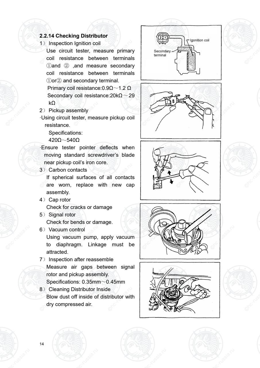
1) Inspection Ignition coil
Use circuit tester, measure primary
coil resistance between terminals
①and ② ,and measure secondary
coil resistance between terminals
①or② and secondary terminal.
Primary coil resistance:0.9Ω~1.2 Ω
Secondary coil resistance:20kΩ~29
kΩ
2) Pickup assembly
·Using circuit tester, measure pickup coil
resistance.
Specifications:
420Ω~540Ω
·Ensure tester pointer deflects when
moving standard screwdriver’s blade
near pickup coil’s iron core.
3) Carbon contacts
If spherical surfaces of all contacts
are worn, replace with new cap
assembly.
4) Cap rotor
Check for cracks or damage
5) Signal rotor
Check for bends or damage.
6) Vacuum control
Using vacuum pump, apply vacuum
to diaphragm. Linkage must be
attracted.
7) Inspection after reassemble
Measure air gaps between signal
rotor and pickup assembly.
Specifications: 0.35mm~0.45mm
8) Cleaning Distributor Inside
Blow dust off inside of distributor with
dry compressed air.
Оригинальная страница: таблицы и схемы
Страница 19
15
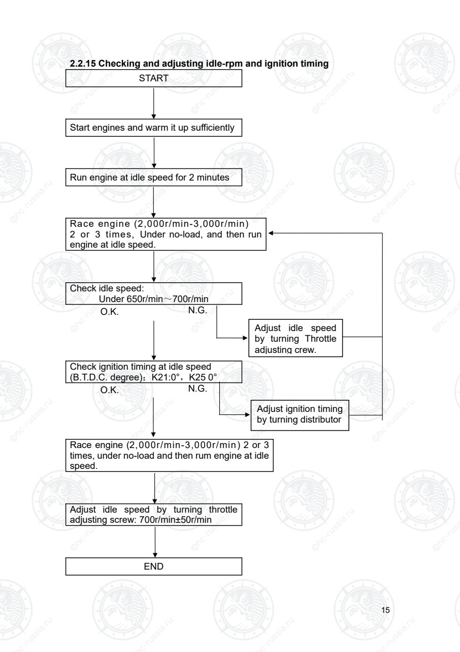
2.2.15 Checking and adjusting idle-rpm and ignition timing
START
Start engines and warm it up sufficiently
Run engine at idle speed for 2 minutes
Race engine (2,000r/min-3,000r/min)
2 or 3 times, Under no-load, and then run
engine at idle speed.
Check idle speed:
Under 650r/min~700r/min
O.K. N.G.
Check ignition timing at idle speed
(B.T.D.C. degree):K21:0°,K25 0°
O.K. N.G.
Race engine (2,000r/min-3,000r/min) 2 or 3
times, under no-load and then rum engine at idle
speed.
Adjust idle speed by turning throttle
adjusting screw: 700r/min±50r/min
END
Adjust idle speed
by turning Throttle
adjusting crew.
Adjust ignition timing
by turning distributor
Оригинальная страница: таблицы и схемы
Страница 20
16
CAUTION:
1) Don’t attempt to screw the idle adjusting screw down completely.
Doing so could cause damage to tip, which in turn will tend to cause
malfunctions.
2) Make sure that the following parts are in good order.
·Ignition system
·Engine oil and coolant levels
·Valve clearance
·Float level at idling speed
Set shift lever in “Neutral” position.
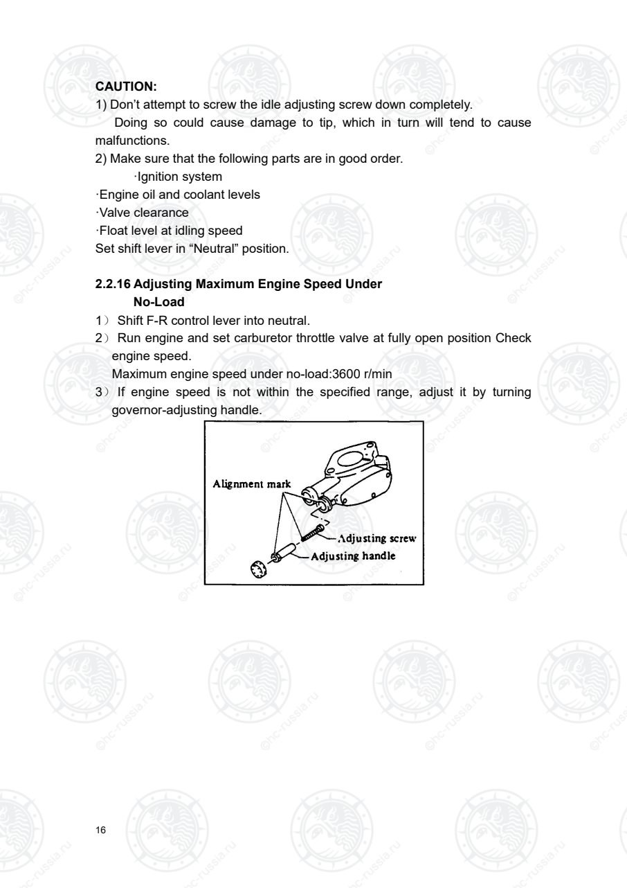
2.2.16 Adjusting Maximum Engine Speed Under
No-Load
1) Shift F-R control lever into neutral.
2) Run engine and set carburetor throttle valve at fully open position Check
engine speed.
Maximum engine speed under no-load:3600 r/min
3) If engine speed is not within the specified range, adjust it by turning
governor-adjusting handle.
Оригинальная страница: таблицы и схемы
Страница 21
17
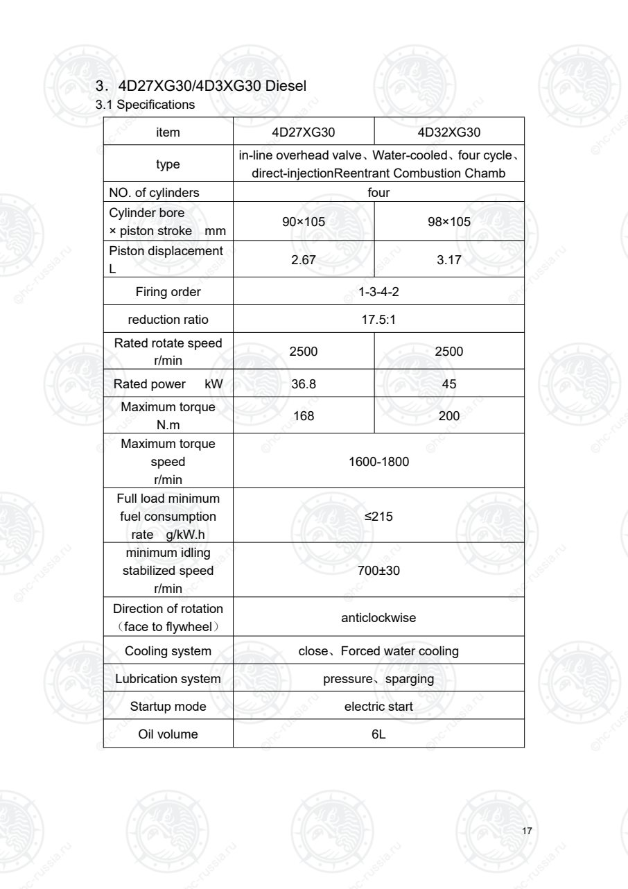
3.4D27XG30/4D3XG30 Diesel
3.1 Specifications
item 4D27XG30 4D32XG30
type in-line overhead valve、Water-cooled、four cycle、
direct-injectionReentrant Combustion Chamb
NO. of cylinders four
Cylinder bore
× piston stroke mm 90×105 98×105
Piston displacement
L 2.67 3.17
Firing order 1-3-4-2
reduction ratio 17.5:1
Rated rotate speed
r/min 2500 2500
Rated power kW 36.8 45
Maximum torque
N.m 168 200
Maximum torque
speed
r/min
1600-1800
Full load minimum
fuel consumption
rate g/kW.h
≤215
minimum idling
stabilized speed
r/min
700±30
Direction of rotation
(face to flywheel) anticlockwise
Cooling system close、Forced water cooling
Lubrication system pressure、sparging
Startup mode electric start
Oil volume 6L
Оригинальная страница: таблицы и схемы
Страница 22
18
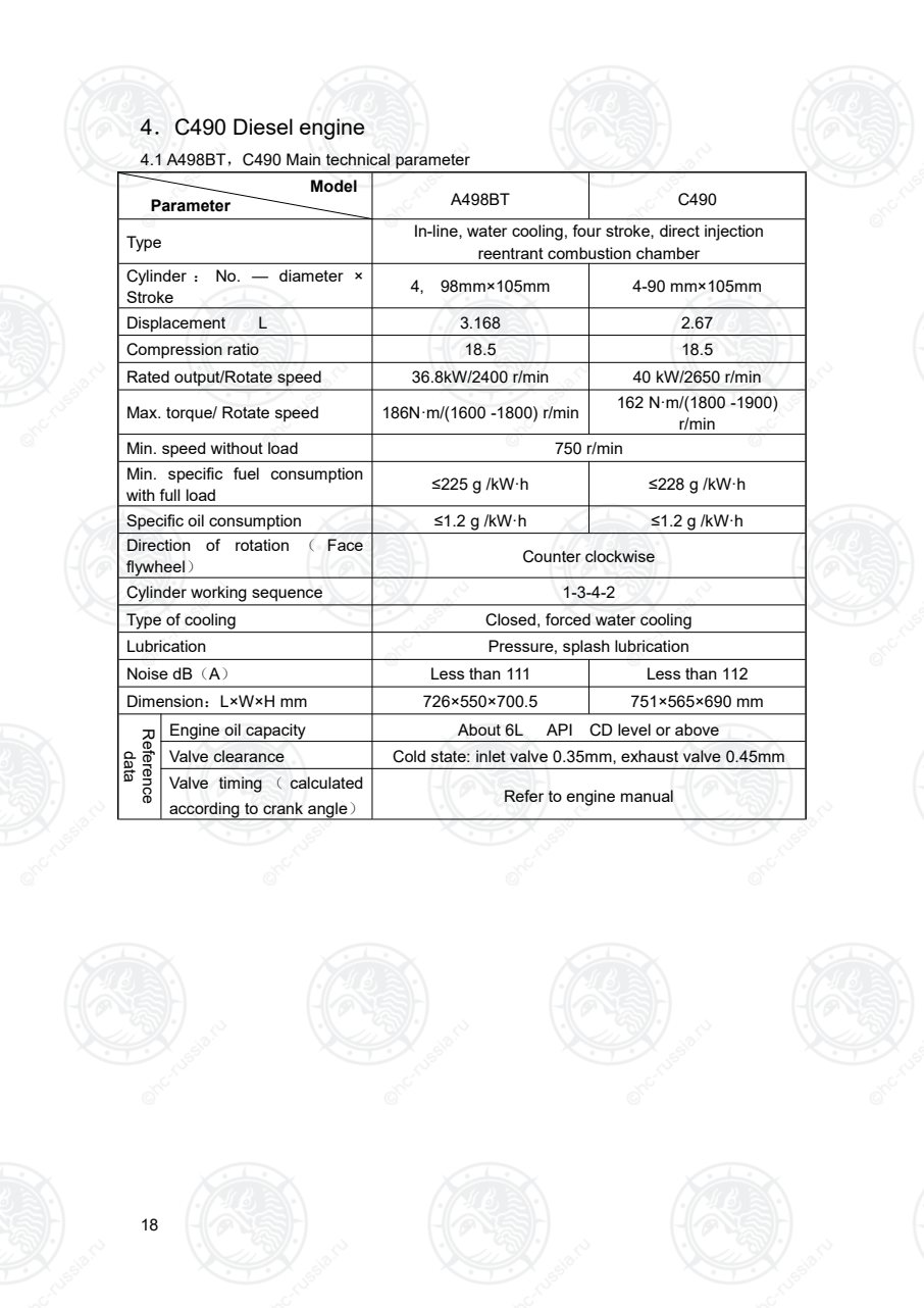
4.C490 Diesel engine
4.1 A498BT,C490 Main technical parameter
Model
Parameter A498BT C490
Type In-line, water cooling, four stroke, direct injection
reentrant combustion chamber
Cylinder : No. — diameter ×
Stroke 4, 98mm×105mm 4-90 mm×105mm
Displacement L 3.168 2.67
Compression ratio 18.5 18.5
Rated output/Rotate speed 36.8kW/2400 r/min 40 kW/2650 r/min
Max. torque/ Rotate speed 186N·m/(1600 -1800) r/min 162 N·m/(1800 -1900)
r/min
Min. speed without load 750 r/min
Min. specific fuel consumption
with full load ≤225 g /kW·h ≤228 g /kW·h
Specific oil consumption ≤1.2 g /kW·h ≤1.2 g /kW·h
Direction of rotation ( Face
flywheel) Counter clockwise
Cylinder working sequence 1-3-4-2
Type of cooling Closed, forced water cooling
Lubrication Pressure, splash lubrication
Noise dB(A) Less than 111 Less than 112
Dimension:L×W×H mm 726×550×700.5 751×565×690 mm
Reference
data
Engine oil capacity About 6L API CD level or above
Valve clearance Cold state: inlet valve 0.35mm, exhaust valve 0.45mm
Valve timing ( calculated
according to crank angle) Refer to engine manual
Оригинальная страница: таблицы и схемы
Страница 23
19
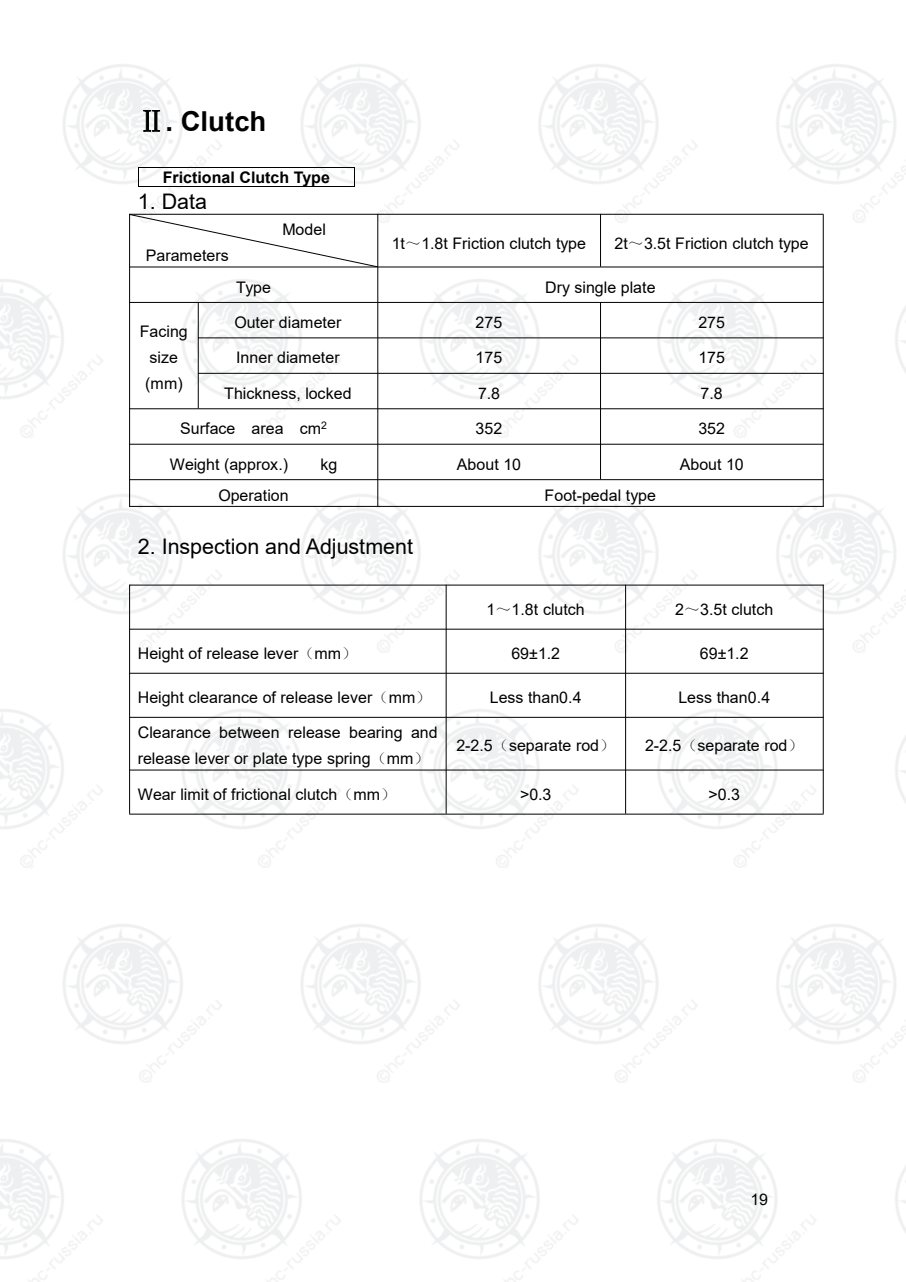
Ⅱ. Clutch
Frictional Clutch Type
1. Data
Model
Parameters
1t~1.8t Friction clutch type 2t~3.5t Friction clutch type
Type Dry single plate
Facing
size
(mm)
Outer diameter 275 275
Inner diameter 175 175
Thickness, locked 7.8 7.8
Surface area cm2 352 352
Weight (approx.) kg About 10 About 10
Operation Foot-pedal type
2. Inspection and Adjustment
1~1.8t clutch 2~3.5t clutch
Height of release lever(mm) 69±1.2 69±1.2
Height clearance of release lever(mm) Less than0.4 Less than0.4
Clearance between release bearing and
release lever or plate type spring(mm)
2-2.5(separate rod) 2-2.5(separate rod)
Wear limit of frictional clutch(mm) >0.3 >0.3
Оригинальная страница: таблицы и схемы
Страница 24
20
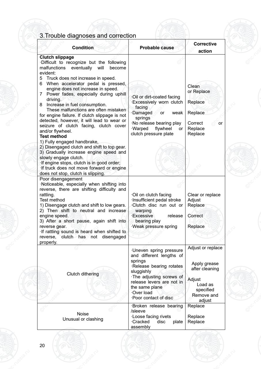
3.Trouble diagnoses and correction
Condition Probable cause
Corrective
action
Clutch slippage
·Difficult to recognize but the following
malfunctions eventually will become
evident:
5 Truck does not increase in speed.
6 When accelerator pedal is pressed,
engine does not increase in speed.
7 Power fades, especially during uphill
driving.
8 Increase in fuel consumption.
These malfunctions are often mistaken
for engine failure. If clutch slippage is not
detected, however, it will lead to wear or
seizure of clutch facing, clutch cover
and/or flywheel.
Test method
1) Fully engaged handbrake,
2) Disengaged clutch and shift to top gear.
3) Gradually increase engine speed and
slowly engage clutch.
·If engine stops, clutch is in good order;
·If truck does not move forward or engine
does not stop, clutch is slipping.
·Oil or dirt-coated facing
·Excessively worn clutch
facing
·Damaged or weak
springs
·No release bearing play
·Warped flywheel or
clutch pressure plate
Clean
or Replace
Replace
Replace
Correct or
Replace
Replace
Poor disengagement
·Noticeable, especially when shifting into
reverse, there are shifting difficulty and
rattling.
Test method
1) Disengage clutch and shift to low gears.
2) Then shift to neutral and increase
engine speed.
3) After a short pause, again shift into
reverse gear.
·If rattling sound is heard when shifted to
reverse, clutch has not disengaged
properly.
·Oil on clutch facing
·Insufficient pedal stroke
·Clutch disc run out or
warping
·Excessive release
bearing play
·Weak pressure spring
Clear or replace
Adjust
Replace
Correct
Replace
Clutch dithering
·Uneven spring pressure
and different lengths of
springs
·Release bearing rotates
sluggishly
·The adjusting screws of
release levers are not in
the same plane
·Over load
·Poor contact of disc
Adjust or replace
Apply grease
after cleaning
Adjust
Load as
specified
Remove and
adjust
Noise
Unusual or clashing
·Broken release bearing
/sleeve
·Loose facing rivets
·Cracked disc plate
assembly
Replace
Replace
Replace
Оригинальная страница: таблицы и схемы
Страница 25
21
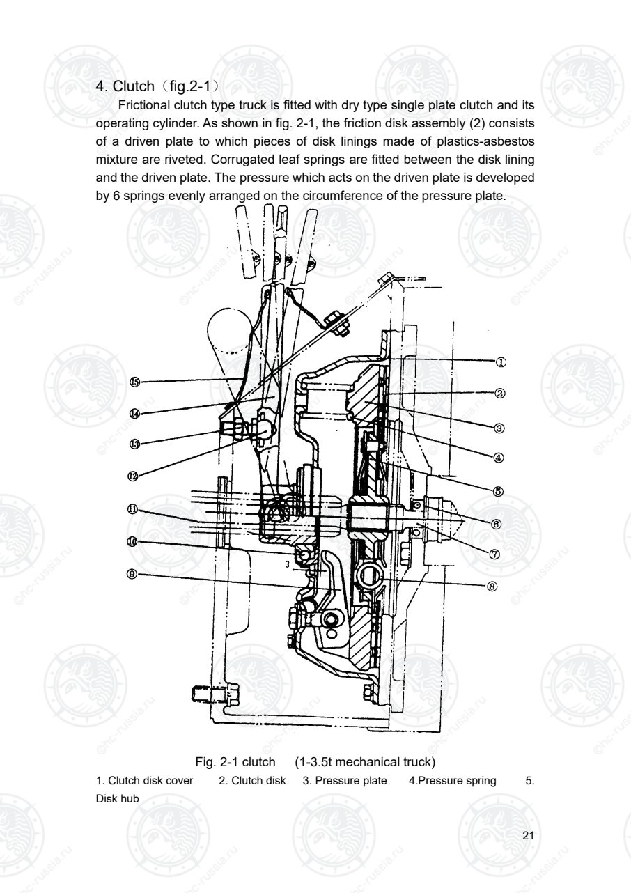
4. Clutch(fig.2-1)
Frictional clutch type truck is fitted with dry type single plate clutch and its
operating cylinder. As shown in fig. 2-1, the friction disk assembly (2) consists
of a driven plate to which pieces of disk linings made of plastics-asbestos
mixture are riveted. Corrugated leaf springs are fitted between the disk lining
and the driven plate. The pressure which acts on the driven plate is developed
by 6 springs evenly arranged on the circumference of the pressure plate.
Fig. 2-1 clutch (1-3.5t mechanical truck)
1. Clutch disk cover 2. Clutch disk 3. Pressure plate 4.Pressure spring 5.
Disk hub
Оригинальная страница: таблицы и схемы
Страница 26
22
6. Release bearing 7. Main shaft 8. Coil spring 9.Release rod 10.
Release sleeve
11. Release rock pin 12. Support bolt 13. Nut 14. Push rod 15.Cover
4.1 Inspection and adjustment
1) A clearance of 2-2.5mm is required between the top of release lever 9 and
the end face of release bearing when the clutch is engaged. This clearance
is needed to prevent release bearing and friction lining from damaging.
Because the truck is constantly being accelerated and direction attention to
pay to adjusting the clearance.
2) Check the three release levers of clutch for deviation, which is allowed
less than 0.4mm. Otherwise, it should be adjusted. Tighten lock nut after
adjusting.
4.2 Replacement of clutch disk
1)Press down the clutch pedal; and place spacers between the clutch cover
and release lever engines, install 2 pull-up bolts on the clutch cover.
2)Turn the slide bolt (fig.3-1) to the left to bring the drive shaft into the
transmission.
3)Remove the 6 clutch cover-mounting bolts, and take off the clutch disk.
4)Install a new clutch disk, with the longer spline pointing towards the
transmission.
5)Turn the slide bolt step by step to the right and pull it out, matching the drive
shaft spline with the clutch disk spline.
6)After making sure the drive shaft end has entered the pilot bearing, tighten
the drive shaft spline with the clutch disk spline. Torque is 107~119N·m.
7)Install the clutch cover on the flywheel.
8)Press the clutch pedal and 3 remove spaces.
9)Adjust the clutch pedal.
Оригинальная страница: таблицы и схемы
Страница 27
23
Ⅲ. Manual transmission、reduction gear and
differential
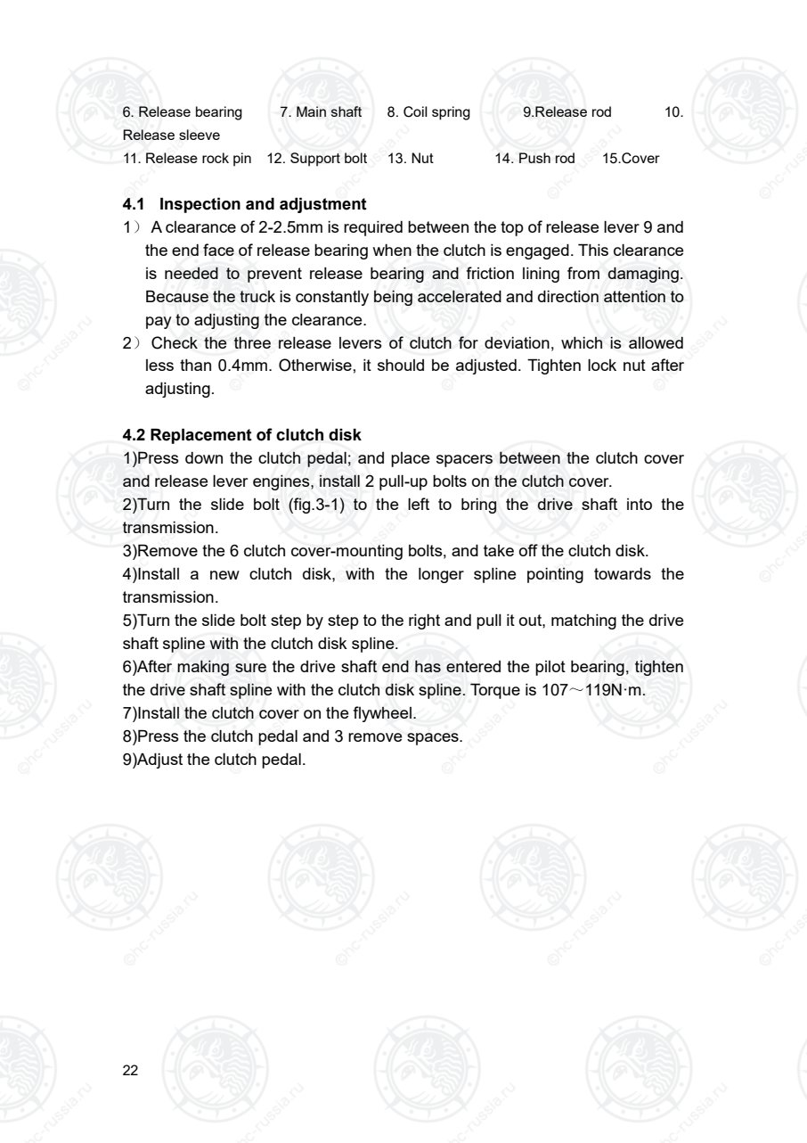
1.Parameter
Gearbox type
item
XJDS18 XJDS25 XJDS30
Gearbox weight(kg) 105 130
Match the engine rated power
(kW)
25~33 33~45
Match engine rated speed
(r/min)
2200~2650
Match the engine maximum
torque(N.m)
85~150 140~210
Gear
ratio
Forwards
F1=37.0791
F2=16.0405
F1=38.136
F2=16.498
F1=42.224
F2=18.2662
Backwards
R1=36.5311
R1=15.8034
R1=37.573
R1=16.254
R1=41.6
R2=17.9962
Synchronizer type Inertia lock ring
Shift type Manual shift
direction of rotation(face to input
terminal)
Clockwise
Using oil type Vehicle gear oilGL-5 85 W /90
Capacity(L) ≈8.5(To drive the oil hole on the bridge shall prevail)
Working oil temperature(℃) 60~80
The highest oil temperature(℃) 120(not exceeding 5min)
overall dimension
( length×width×height ) mm×
mm× mm
785×460×440 851×460×490
Remark: ·Lubricating oil should be added by the vent hole of drive axis
because of communicating between axis housing and transmission case.
·Use genuine lubricating oil designated by HANGCHA.
Оригинальная страница: таблицы и схемы
Страница 28
24
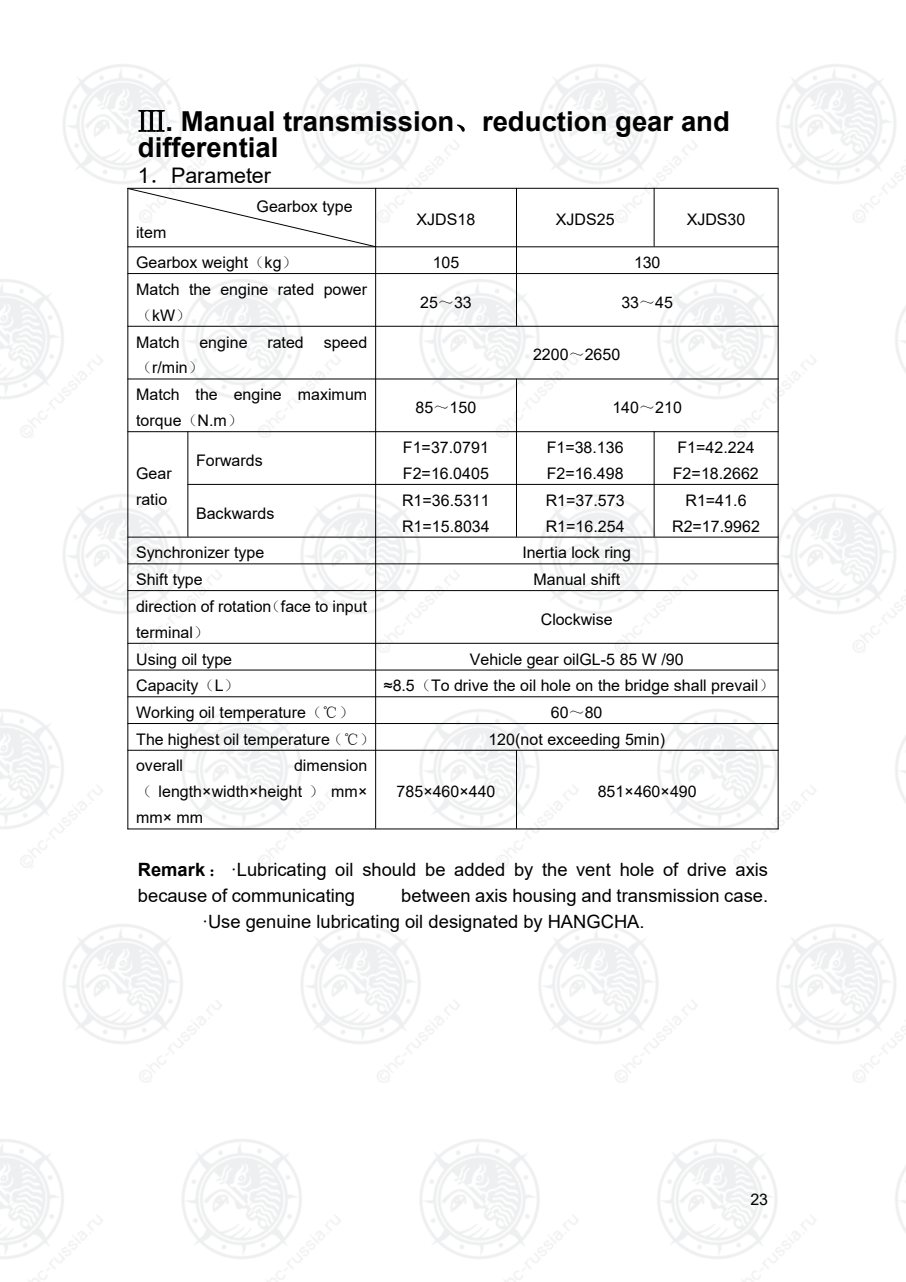
2.Trouble diagnoses and correction
Condition Probable cause correct action
Great
vibration
• Loose securing bolt on each fixing and
connecting
tighten
Overheating
of oil
·Deteriorate gear oil
·Abnormal oil level
·Dragging of moveable piece
replace
fill or reduce
adjust
Oil leakage
·Loose bolt of connecting face
·Broken seal ring
tighten
replace
Noise
·Damaged turn gear
·Damaged bearing
replace
replace
3.Summary
The manual transmission of 1-3.5t manual shift forklift consists of
gearshift, reducer and differential with shifting gear, reducing speed and
carrying out differential transmission. Because of its synchronizer, it makes to
avoid striking between gears when shifting gear and to shift gear tenderly and
smoothly and to reduce shift noise especially when shifting forward or
reversibly and to prolong the gears life-span. 1-1.8t forklift adopts XJDS18
transmission, 2-2.5t forklift adopts XJDS25 and 3-3.5t forklift adopts XJDS30
transmission. The structure and principle for JDS30 transmission are
introduced as follows; Those of XJDS18 and XJDS25 are the same with
JDS30.
4.Gear shift
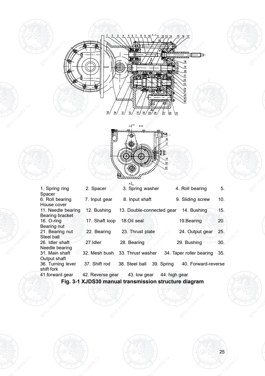
XJDS30 gear shift is mainly composed of an input shaft, an output shaft, a
main shaft, an idle shaft (work in reverse). There is one or several gears with
vary teeth in every shaft, There are installed two group mesh bush type
synchronizer on main shaft. When shifting gear by the shift lever, the output
shaft transmit the power to the drive wheels through low gear, differential and
semi-axis.(as shown in Fig.3-1)
Оригинальная страница: таблицы и схемы
Страница 29
25
1. Spring ring 2. Spacer 3. Spring washer 4. Roll bearing 5.
Spacer
6. Roll bearing 7. Input gear 8. Input shaft 9. Sliding screw 10.
House cover
11. Needle bearing 12. Bushing 13. Double-connected gear 14. Bushing 15.
Bearing bracket
16. O-ring 17. Shaft loop 18.Oil seal 19.Bearing 20.
Bearing nut
21. Bearing nut 22. Bearing 23. Thrust plate 24. Output gear 25.
Steel ball
26. Idler shaft 27.Idler 28. Bearing 29. Bushing 30.
Needle bearing
31. Main shaft 32. Mesh bush 33. Thrust washer 34. Taper roller bearing 35.
Output shaft
36. Turning lever 37. Shift rod 38. Steel ball 39. Spring 40. Forward-reverse
shift fork
41.forward gear 42. Reverse gear 43. low gear 44. high gear
Fig. 3-1 XJDS30 manual transmission structure diagram
Оригинальная страница: таблицы и схемы
Страница 30
26
1) Input shaft and sliding screw
One end of the input shaft near clutch is put in the ball bearing in flywheel.
Another end’spline installed with input gear (constant mesh with
double-connect gear which fits on output shaft) fix up in ball bearing of
transmission case , and the middle part is installed on bearing carriage
through ball bearing and flexible snap ring, and bearing carriage is installed on
transmission case through sliding screw. When replacing the friction disk
assembly, input shaft and bearing carriage can move along shaft by turning
T-thread of sliding screw so that input shaft move back inside transmission
case.
2) Output shaft
Double-connect gear is fit on the output shaft through two needle gears
and bush and the other end of output shaft is fit output gear with spline
through bush.. The two ends of output shaft are installed by taper roller
bearing and it can be adjusted side clearance of bearing with washer in the
rear end .The gearwheel of double-connect gear engages with input gear and
high gear while the pinion of that engage with low gear. And that output gear
constant engages with forward gear and reverses idler wheel.
3) Main shaft
High gear, low gear, reverse gear and forward gear are all installed on
main shaft. Because they constant engage with double-connect gear, reverse
idler wheel and output gear separately, it can carry through to shift gear or
change direction by operating synchromesh on main shaft.
The gearshift of XJDS18 manual transmission is the same with that of
XJDS30 manual transmission except gear of output shaft.
4) Idler shaft
Idler shaft is fixed on the transmission case which rear end uses ball for
locking. Idler wheel is installed on idler shaft with needle bearing, which
constant engage with reverse gear and output gear separately.
5) Turning lever and shifting yoke
Two turning levers 36 are applied to shift between high gear and low gear
and between forward and reverse direction. Fork 40 is supported on shifting
lever 37 and Ball 38 is locked inside the groove of shifting lever through spring
39 in order to fix shifting position.
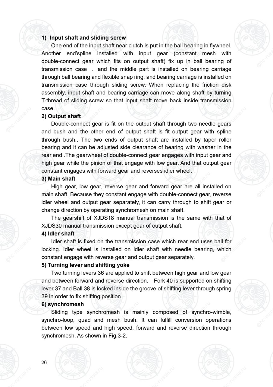
6) synchromesh
Sliding type synchromesh is mainly composed of synchro-wimble,
synchro-loop, quad and mesh bush. It can fulfill conversion operations
between low speed and high speed, forward and reverse direction through
synchromesh. As shown in Fig.3-2.
Оригинальная страница: таблицы и схемы
Страница 31
27
1. Synchro-loop spline tooth
2.Synchro-loop
3. Spline tooth of gear⑾
4.Synchro-wimble
5.Mesh bush
6. spline of mesh bush
7. Quad
8.Spring
9. Clutch driven disc hub
10. Forward-reverse shift fork
11. Constant-mesh gear
12. Tooth of gear⑾
13. Constant-mesh gear
14. Tooth of gear⒁
Fig.3-2 synchro mesh
1. Synchro-wimble:gear 11 or 13 has a wimble(synchro-wimble) and involute
spline, which links separately with synchro-loop(piece 2) and mesh bush
(piece 5) through friction face of the wimble and spline.
2. Synchro-loop:Synchro-loop has a bore wimble which friction face links with
synchro-wimble and it also has three grooves which set equally along
circle and which suit with splines of mesh bush and synchro-loop in order
to press to synchro-loop through spline 6 of mesh bush.
3. Quad:Assemble the middle bulge of three quads in spline of mesh bush 5,
which two ends implant corresponding three grooves of synchro-loop.
Quad is pressed to the top of spline 6 through two springs 8 while
outwards spring force makes spline tooth of synchro-loop usually in the
middle position.
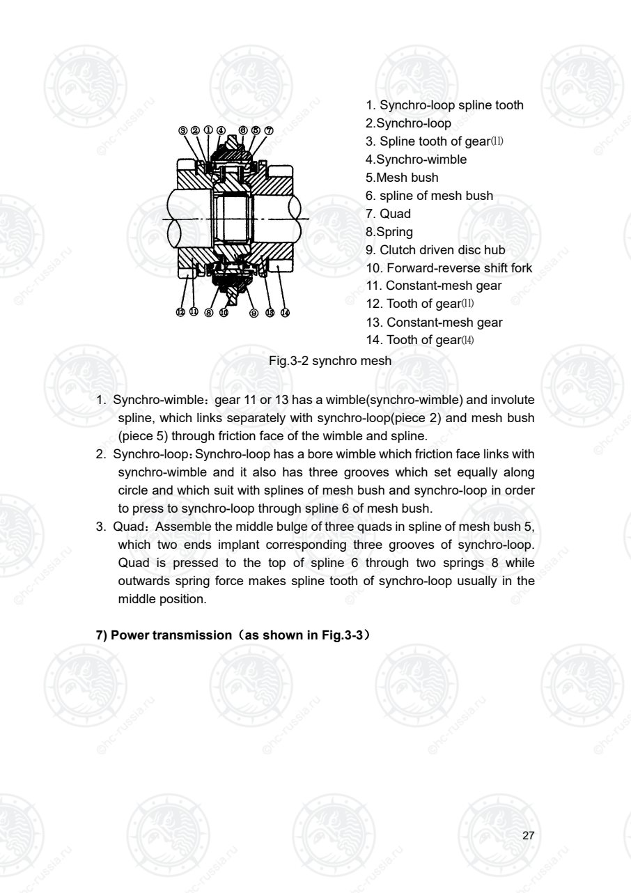
7) Power transmission(as shown in Fig.3-3)
Оригинальная страница: таблицы и схемы
Страница 32
28
1.Drive shaft 2. Input gear 3. Double-connected gear 4. Double-connected gear 5.
Output gear
6 . High gear 7. Synchro-wimble 8. Mesh bush 9.Clutch driven plate hub 10.
Synchro-wimble
11. low gear 12. Main shaft 13. Reverse gear 14. Synchro-wimble
15. Mesh bush
16. Clutch driven plate hub 17. Synchro-wimble 18. Forward gear 19.
Reverse gear
20. Reverse gear 21.Output shaft 22. Idler shaft
Fig.3-3 Manual transmission drive diagram
Neutral position(neutral)
Power from input shaft 1 transfers to high gear 6 and low gear 11 through
meshing input gear 2 and double-connect gear 3. But the shift mesh bush
which controls speed and direction is in neutral, and main shaft output gear
and output shaft cannot rotate so that power cannot output.
Shift position — When shift gear lever, yoke drive mesh bush to move so
that each gear mesh through synchromesh. Power transmission procedure is
as follows: input shaft→input gear→double connect gear→high or low
gear→synchromesh→main shaft→synchromesh→reverse gear or forward
gear→output gear→output shaft
Forward 1st speed power transmission procedure:
1→2→3→4→11→10→8→9→12→16→15→17→18→5→21
Forward 2nd speed power transmission procedure:
1→2→3→6→7→8→9→12→16→15→17→18→5→21
Reverse 1st speed power transmission procedure:
1→2→3→4→11→10→8→9→12→16→15→14→13→19→20→5→21
Оригинальная страница: таблицы и схемы
Страница 33
29
Reverse 2nd speed power transmission procedure:
1→2→3→6→7→8→9→12→16→15→14→13→19→20→5→21
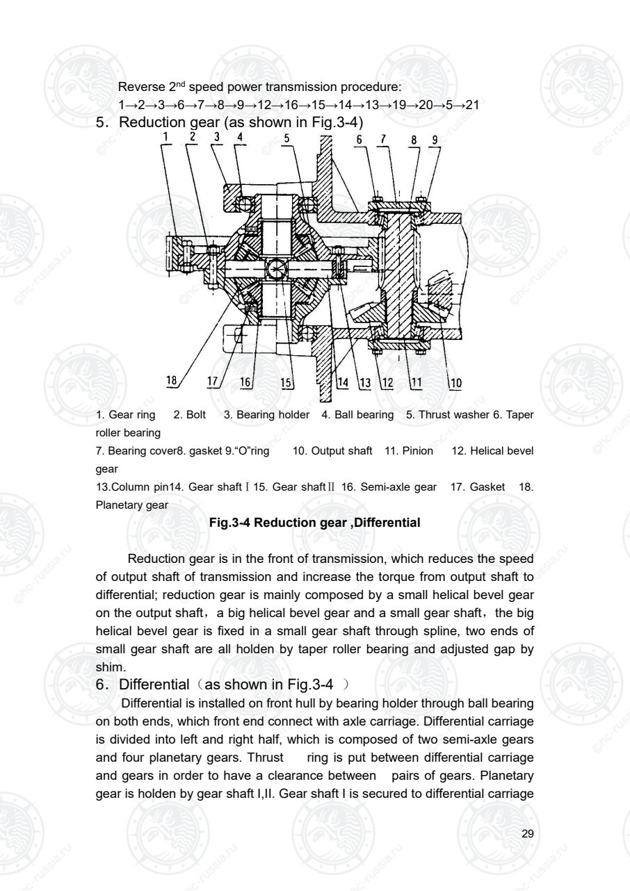
5.Reduction gear (as shown in Fig.3-4)
1. Gear ring 2. Bolt 3. Bearing holder 4. Ball bearing 5. Thrust washer 6. Taper
roller bearing
7. Bearing cover8. gasket 9.“O”ring 10. Output shaft 11. Pinion 12. Helical bevel
gear
13.Column pin14. Gear shaftⅠ15. Gear shaftⅡ 16. Semi-axle gear 17. Gasket 18.
Planetary gear
Fig.3-4 Reduction gear ,Differential
Reduction gear is in the front of transmission, which reduces the speed
of output shaft of transmission and increase the torque from output shaft to
differential; reduction gear is mainly composed by a small helical bevel gear
on the output shaft,a big helical bevel gear and a small gear shaft,the big
helical bevel gear is fixed in a small gear shaft through spline, two ends of
small gear shaft are all holden by taper roller bearing and adjusted gap by
shim.
6.Differential(as shown in Fig.3-4 )
Differential is installed on front hull by bearing holder through ball bearing
on both ends, which front end connect with axle carriage. Differential carriage
is divided into left and right half, which is composed of two semi-axle gears
and four planetary gears. Thrust ring is put between differential carriage
and gears in order to have a clearance between pairs of gears. Planetary
gear is holden by gear shaft I,II. Gear shaft I is secured to differential carriage
Оригинальная страница: таблицы и схемы
Страница 34
30
by columnar pin, and gear loop 1 is secured to differential carriage byream
bolt .
The power from transmission transmits to wheel through semi-axle gear
and semi-axle when it is reduced to come into differential driving by
differential.
7.Replace for yoke(as shown in Fig.3-1)
① Remove first the bolts securing shaft arm to back end side shift lever 37;
② Pull out shaft arm slightly;
③ Remove cover fixing bolts and cover;
④ Make quickly gear shift, from forward to reverse or from reverse to forward,
to separate shift lever front end from transmission housing;
5 Pull out shaft arm;
⑥ Remove spring snap ring on outer end of turning lever 36;
⑦ Gently beat turning lever nob, and remove turning lever.
Caution:Don’t beat too heavily, forbid striking.
8 Remove yoke 40 together with shift lever 36. Take down yoke from shift
lever.
Caution:
·This time should recognize the shift position of yoke.
·Keeping spring 39 and steel ball 38 inside yoke hole.
8.Reassemble yoke
Caution:
·Reassemble in clean site to prevent dust and
impurity from entering into case.
·Check each part for wearing, replace if any worn.
·Always replace seal thing and “o” ring.
1 Install spring and steel ball in yoke hole, set yoke into shift lever and get
well by beat gently.
Caution:
·The position of yoke should be that before removing.
·The steel ball on yoke should drop in corresponding
groove of shift lever.
② Make yoke meet groove of mesh bush well, meanwhile install yoke together
with shift lever in case.
③ Assemble shaft arm. please notice the position of shift lever.
④ Before tightening lock bolt on the end of shaft arm, please tighten two fixing
bolt in the range of 28.4 N·m ~44N·m
⑤ After insert front end of shift lever into case, tighten lock bolt in the range of
Оригинальная страница: таблицы и схемы
Страница 35
31
7.8 N·m ~17.6 N·m and then tighten lock nut in the range of 13.7 N·m
~23.5 N·m.
⑥ Install turning lever together with “o” ring into case and lock with spring
snap ring.
⑦ Install gasket of case cover together with cover into case, and tighten each
bolt symmetrically, equally and in turn in the range of 20.6 N·m ~34.3 N·m.
9.Remove transmission assemble
Removal of transmission is according to following procedures:
9.1 Remove differential(as shown in Fig.3-4)
1) Take down bolts securing bearing seat of differential.
2) Take down the section of differential from transmission.
3) Loose and take down bolt 2 and column 13, detach differential left hull
from right hull.
4) Take respectively down thrust washer 5, gear 14, planetary gear18,
semi-axle gear 16, washer 17, gear shaft 15 etc..
Caution:Be sure to lay adjust shim dividually and not to be mixed up.
9.2 Remove reduction gear(as shown in Fig.3-4)
1) Loose and take down the fixing bolts of two ends of bearing cover 7.
2) Gently tap the front of pinion 11 near helical bevel gear.
3) Take down bearing 6, pinion 11, helical bevel gear 12.
Caution:Be sure location of adjust shim 8, and adjust shim of both ends should be lay
dividuallyandnot be mixed up.
9.3 Remove gear shift(as shown in Fig.3-1)
9.3.1 Unscrew sliding screw 9; take down “o” ring16.
9.3.2 Take down snap ring 3 using in bore on case with caliper, and take down
input gear 7 from case.
9.3.3 Take down snap ring using in bore from bearing holder 15, gently beat
right end of input shaft in order to detach it from bearing holder 15. Take down
input shaft 8 and then take down bearing holder from case.
1) Remove yoke
The procedure of removing yoke is as shown in 6.
9.3.5 Remove input shaft
2 Loose nut 20, 21, gently beat the right end of output shaft 35.
3 Take down output shaft and all parts on it.
9.3.6 Remove main shaft
1. Remove snap ring using in shaft in the right of main shaft 31.
2. Remove bearing holding ring using two thread hole of bearing
holding ring 41.
3. Take down main shaft components, and take down all parts on the
Оригинальная страница: таблицы и схемы
Страница 36
32
main shaft. Snap ring using in shaft may be removed with caliper.
Caution:Be sure location of adjust shim.
9.3.7 Idler
1) Gently tap the left of idler shaft.
2) Take down idler shaft from case, and take down all parts on it.
9.4 Assembly
Assemble in the reverse order of removal, but be sure:
a. Prevent each fixing connecting face and gear tooth surface from knocking
to be damaged.
b. Apply working faces of parts such as bearing, gear, seal ring and relatively
movement parts with a little gear oil to prevent them from coming into being
instant dry friction while early running.
c. Each part should be assembled correctly.
d. Each part should be running smoothly to prevent it from getting stuck.
e. Be sure to tighten firmly each joint bolt.
Оригинальная страница: таблицы и схемы
Страница 37
33
Ⅳ. XYQXD Hydraulic transmission and torque
converter
1.Data
Models XYQXD18 XYQXD25 XYQXD30
power rating KW 24―33 33―40
rated speed r/min 2300―2600 2250―2650
Transmission
ratio
Forwards 19.2065 15.3652 17.4972
Backwards 19.2065 15.3652 17.4972
Main oil pressure Mpa 1.1―1.4
Inlet Pressure of torque Converter
Mpa
0.5―0.7
Electrical device(V·DC//W) 12V·DC/26W
Hydrodynamic
torque
converter
Models YJH265
Diameter of
circulating chamber
D(mm)
265
Max. torque
converter ratio K0
3±0.15
Max efficiency
ηmax
>0.79
Zero speed
operating conditions
Nominal torque
N.m
33.5±1.7
Nominal torque of
pump wheel with
maximum efficiency
N.m
31±1.6
direction of rotation ( face to input
terminal)
Clockwise
Using oil type No.6
Working oil temperature℃ 70―95
The highest oil temperature℃ 120(not exceeding 5min)
overall dimension
( length×width×height) mm× mm×
mm
740x470x450 830x470x450
Mass (kg) 160 165 185
2. Summary
XYQXD18, XYQXD25, XYQXD30 model hydrodynamic transmission gear box consists
Оригинальная страница: таблицы и схемы
Страница 38
34
of hydrodynamic torque converter and power shift which has two shifts(forward/reverse).
It has virtues as follows:
Hydrodynamic transmission gear-box has automatic adaptability for hydrodynamic
transmission output, it can change it’s output torque and rotation speed according to the
external load;
It can absorb and remove the impact liberation that the engine and external load brings to
the transmission system;
Inching valve can make the truck to move a little when the engine in either low speed or
high speed, make the operation easy、 convenient, steady starting, reduce the labor
intension of operators.
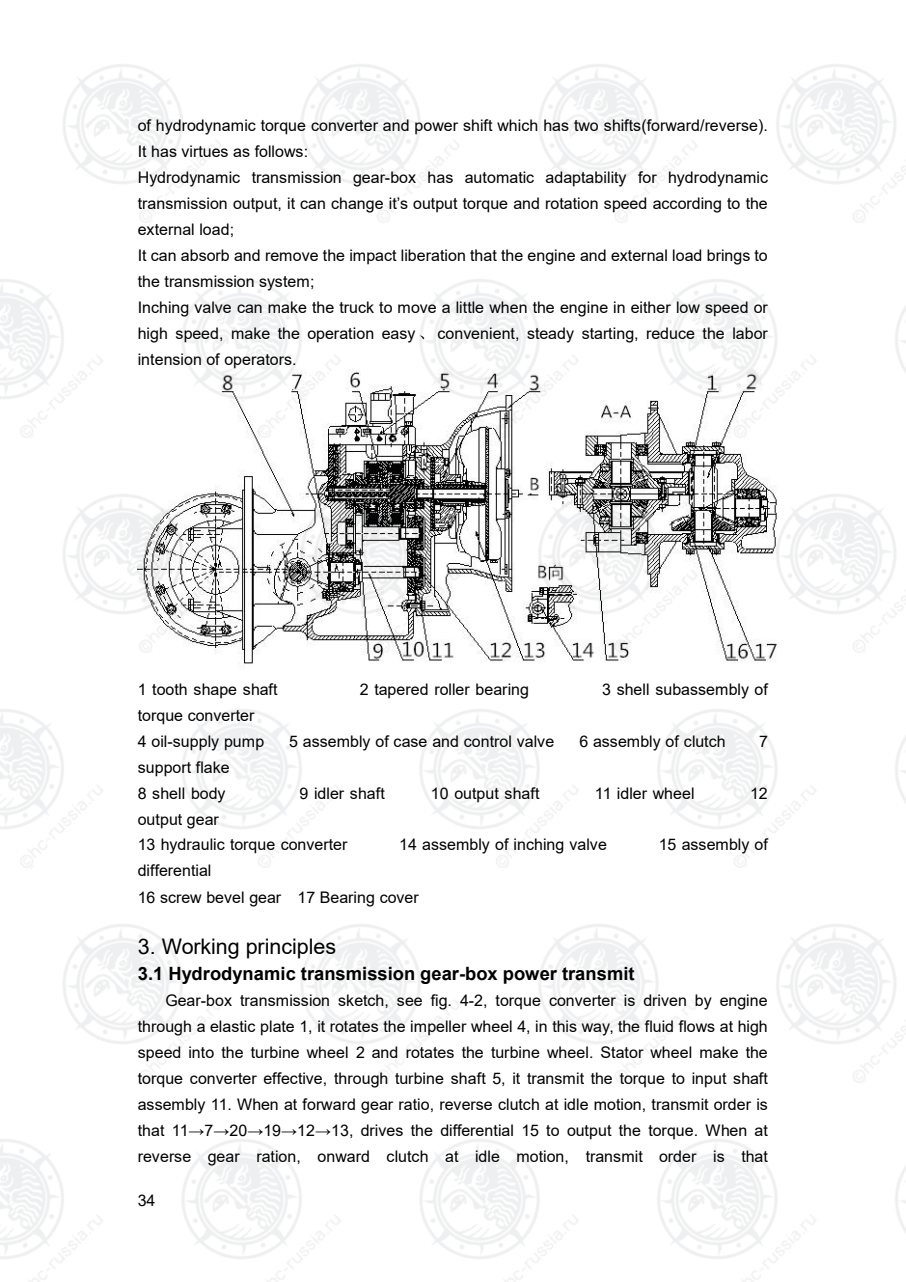
1 tooth shape shaft 2 tapered roller bearing 3 shell subassembly of
torque converter
4 oil-supply pump 5 assembly of case and control valve 6 assembly of clutch 7
support flake
8 shell body 9 idler shaft 10 output shaft 11 idler wheel 12
output gear
13 hydraulic torque converter 14 assembly of inching valve 15 assembly of
differential
16 screw bevel gear 17 Bearing cover
3. Working principles
3.1 Hydrodynamic transmission gear-box power transmit
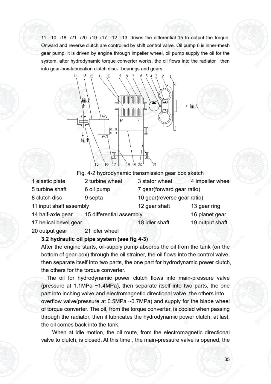
Gear-box transmission sketch, see fig. 4-2, torque converter is driven by engine
through a elastic plate 1, it rotates the impeller wheel 4, in this way, the fluid flows at high
speed into the turbine wheel 2 and rotates the turbine wheel. Stator wheel make the
torque converter effective, through turbine shaft 5, it transmit the torque to input shaft
assembly 11. When at forward gear ratio, reverse clutch at idle motion, transmit order is
that 11→7→20→19→12→13, drives the differential 15 to output the torque. When at
reverse gear ration, onward clutch at idle motion, transmit order is that
Оригинальная страница: таблицы и схемы
Страница 39
35
11→10→18→21→20→19→17→12→13, drives the differential 15 to output the torque.
Onward and reverse clutch are controlled by shift control valve. Oil pump 6 is inner-mesh
gear pump, it is driven by engine through impeller wheel, oil pump supply the oil for the
system, after hydrodynamic torque converter works, the oil flows into the radiator , then
into gear-box-lubrication clutch disc、bearings and gears.
Fig. 4-2 hydrodynamic transmission gear box sketch
1 elastic plate 2 turbine wheel 3 stator wheel 4 impeller wheel
5 turbine shaft 6 oil pump 7 gear(forward gear ratio)
8 clutch disc 9 septa 10 gear(reverse gear ratio)
11 input shaft assembly 12 gear shaft 13 gear ring
14 half-axle gear 15 differential assembly 16 planet gear
17 helical bevel gear 18 idler shaft 19 output shaft
20 output gear 21 idler wheel
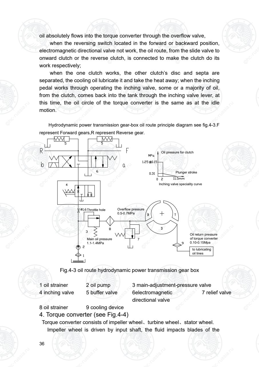
3.2 hydraulic oil pipe system (see fig 4-3)
After the engine starts, oil-supply pump absorbs the oil from the tank (on the
bottom of gear-box) through the oil strainer, the oil flows into the control valve,
then separate itself into two parts, the one part for hydrodynamic power clutch,
the others for the torque converter.
The oil for hydrodynamic power clutch flows into main-pressure valve
(pressure at 1.1MPa ~1.4MPa), then separate itself into two parts, the one
part into inching valve and electromagnetic directional valve, the others into
overflow valve(pressure at 0.5MPa ~0.7MPa) and supply for the blade wheel
of torque converter. The oil, from the torque converter, is cooled when passing
through the radiator, then it lubricates the hydrodynamic power clutch, at last,
the oil comes back into the tank.
When at idle motion, the oil route, from the electromagnetic directional
valve to clutch, is closed. At this time , the main-pressure valve is opened, the
Оригинальная страница: таблицы и схемы
Страница 40
36
oil absolutely flows into the torque converter through the overflow valve,
when the reversing switch located in the forward or backward position,
electromagnetic directional valve not work, the oil route, from the slide valve to
onward clutch or the reverse clutch, is connected to make the clutch do its
work respectively;
when the one clutch works, the other clutch’s disc and septa are
separated, the cooling oil lubricate it and take the heat away; when the inching
pedal works through operating the inching valve, some or a majority of oil,
from the clutch, comes back into the tank through the inching valve lever, at
this time, the oil circle of the torque converter is the same as at the idle
motion.
Hydrodynamic power transmission gear-box oil route principle diagram see fig.4-3.F
represent Forward gears,R represent Reverse gear.
Oil pressure for clutch
Plunger stroke
Inching valve speciality curve
Main oil pressure
1.1-1.4MPa
Throttle hole Overflow pressure
0.5-0.7MPa
Oil return pressure
of torque converter
0.10-0.15Mpa
to lubricating
oil lines
Fig.4-3 oil route hydrodynamic power transmission gear box
1 oil strainer 2 oil pump 3 main-adjustment-pressure valve
4 inching valve 5 buffer valve 6electromagnetic
directional valve
7 relief valve
8 oil strainer 9 cooling device
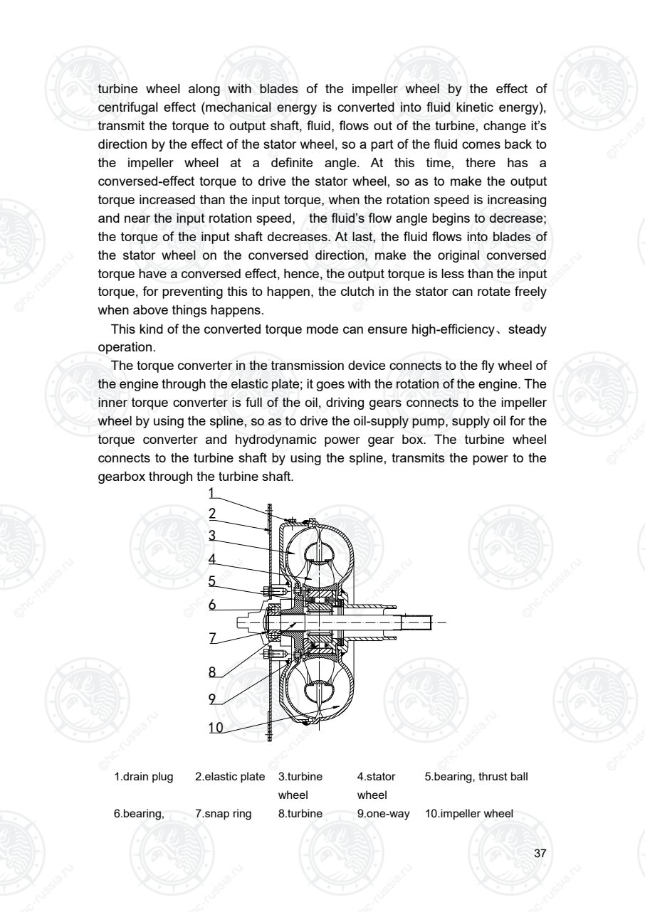
4. Torque converter (see Fig.4-4)
Torque converter consists of impeller wheel、turbine wheel、stator wheel.
Impeller wheel is driven by input shaft, the fluid impacts blades of the
Оригинальная страница: таблицы и схемы
Страница 41
37
turbine wheel along with blades of the impeller wheel by the effect of
centrifugal effect (mechanical energy is converted into fluid kinetic energy),
transmit the torque to output shaft, fluid, flows out of the turbine, change it’s
direction by the effect of the stator wheel, so a part of the fluid comes back to
the impeller wheel at a definite angle. At this time, there has a
conversed-effect torque to drive the stator wheel, so as to make the output
torque increased than the input torque, when the rotation speed is increasing
and near the input rotation speed, the fluid’s flow angle begins to decrease;
the torque of the input shaft decreases. At last, the fluid flows into blades of
the stator wheel on the conversed direction, make the original conversed
torque have a conversed effect, hence, the output torque is less than the input
torque, for preventing this to happen, the clutch in the stator can rotate freely
when above things happens.
This kind of the converted torque mode can ensure high-efficiency、steady
operation.
The torque converter in the transmission device connects to the fly wheel of
the engine through the elastic plate; it goes with the rotation of the engine. The
inner torque converter is full of the oil, driving gears connects to the impeller
wheel by using the spline, so as to drive the oil-supply pump, supply oil for the
torque converter and hydrodynamic power gear box. The turbine wheel
connects to the turbine shaft by using the spline, transmits the power to the
gearbox through the turbine shaft.
8
9
2
3
4
6
7
5
10
1
1.drain plug 2.elastic plate 3.turbine
wheel
4.stator
wheel
5.bearing, thrust ball
6.bearing, 7.snap ring 8.turbine 9.one-way 10.impeller wheel
Оригинальная страница: таблицы и схемы
Страница 42
38
ball shaft clutch
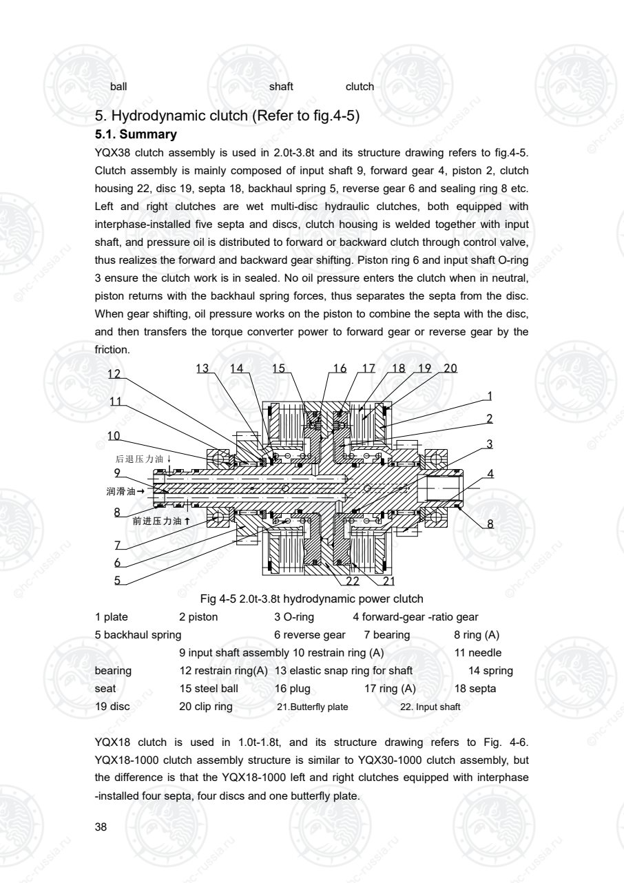
5. Hydrodynamic clutch (Refer to fig.4-5)
5.1. Summary
YQX38 clutch assembly is used in 2.0t-3.8t and its structure drawing refers to fig.4-5.
Clutch assembly is mainly composed of input shaft 9, forward gear 4, piston 2, clutch
housing 22, disc 19, septa 18, backhaul spring 5, reverse gear 6 and sealing ring 8 etc.
Left and right clutches are wet multi-disc hydraulic clutches, both equipped with
interphase-installed five septa and discs, clutch housing is welded together with input
shaft, and pressure oil is distributed to forward or backward clutch through control valve,
thus realizes the forward and backward gear shifting. Piston ring 6 and input shaft O-ring
3 ensure the clutch work is in sealed. No oil pressure enters the clutch when in neutral,
piston returns with the backhaul spring forces, thus separates the septa from the disc.
When gear shifting, oil pressure works on the piston to combine the septa with the disc,
and then transfers the torque converter power to forward gear or reverse gear by the
friction.
5
12 13 14
10
11
后退压力油↓
8
前 进 压 力 油 ↑
9
7
6
润 滑 油 →
8
2
3
4
1
17 1815 16 19 20
2122
Fig 4-5 2.0t-3.8t hydrodynamic power clutch
1 plate 2 piston 3 O-ring 4 forward-gear -ratio gear
5 backhaul spring 6 reverse gear 7 bearing 8 ring (A)
9 input shaft assembly 10 restrain ring (A) 11 needle
bearing 12 restrain ring(A) 13 elastic snap ring for shaft 14 spring
seat 15 steel ball 16 plug 17 ring (A) 18 septa
19 disc 20 clip ring 21.Butterfly plate 22. Input shaft
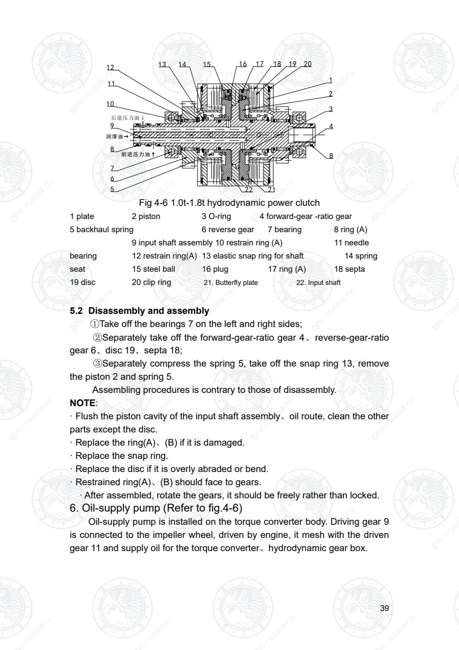
YQX18 clutch is used in 1.0t-1.8t, and its structure drawing refers to Fig. 4-6.
YQX18-1000 clutch assembly structure is similar to YQX30-1000 clutch assembly, but
the difference is that the YQX18-1000 left and right clutches equipped with interphase
-installed four septa, four discs and one butterfly plate.
Оригинальная страница: таблицы и схемы
Страница 43
39
5
12 13 14
10
11
后退压力油↓
8
前 进 压 力 油 ↑
9
7
6
润 滑 油 →
8
2
3
4
1
17 1815 16 19 20
2122
Fig 4-6 1.0t-1.8t hydrodynamic power clutch
1 plate 2 piston 3 O-ring 4 forward-gear -ratio gear
5 backhaul spring 6 reverse gear 7 bearing 8 ring (A)
9 input shaft assembly 10 restrain ring (A) 11 needle
bearing 12 restrain ring(A) 13 elastic snap ring for shaft 14 spring
seat 15 steel ball 16 plug 17 ring (A) 18 septa
19 disc 20 clip ring 21. Butterfly plate 22. Input shaft
5.2 Disassembly and assembly
①Take off the bearings 7 on the left and right sides;
②Separately take off the forward-gear-ratio gear 4、reverse-gear-ratio
gear 6、disc 19、septa 18;
③Separately compress the spring 5, take off the snap ring 13, remove
the piston 2 and spring 5.
Assembling procedures is contrary to those of disassembly.
NOTE:
· Flush the piston cavity of the input shaft assembly、oil route, clean the other
parts except the disc.
· Replace the ring(A)、(B) if it is damaged.
· Replace the snap ring.
· Replace the disc if it is overly abraded or bend.
· Restrained ring(A)、(B) should face to gears.
· After assembled, rotate the gears, it should be freely rather than locked.
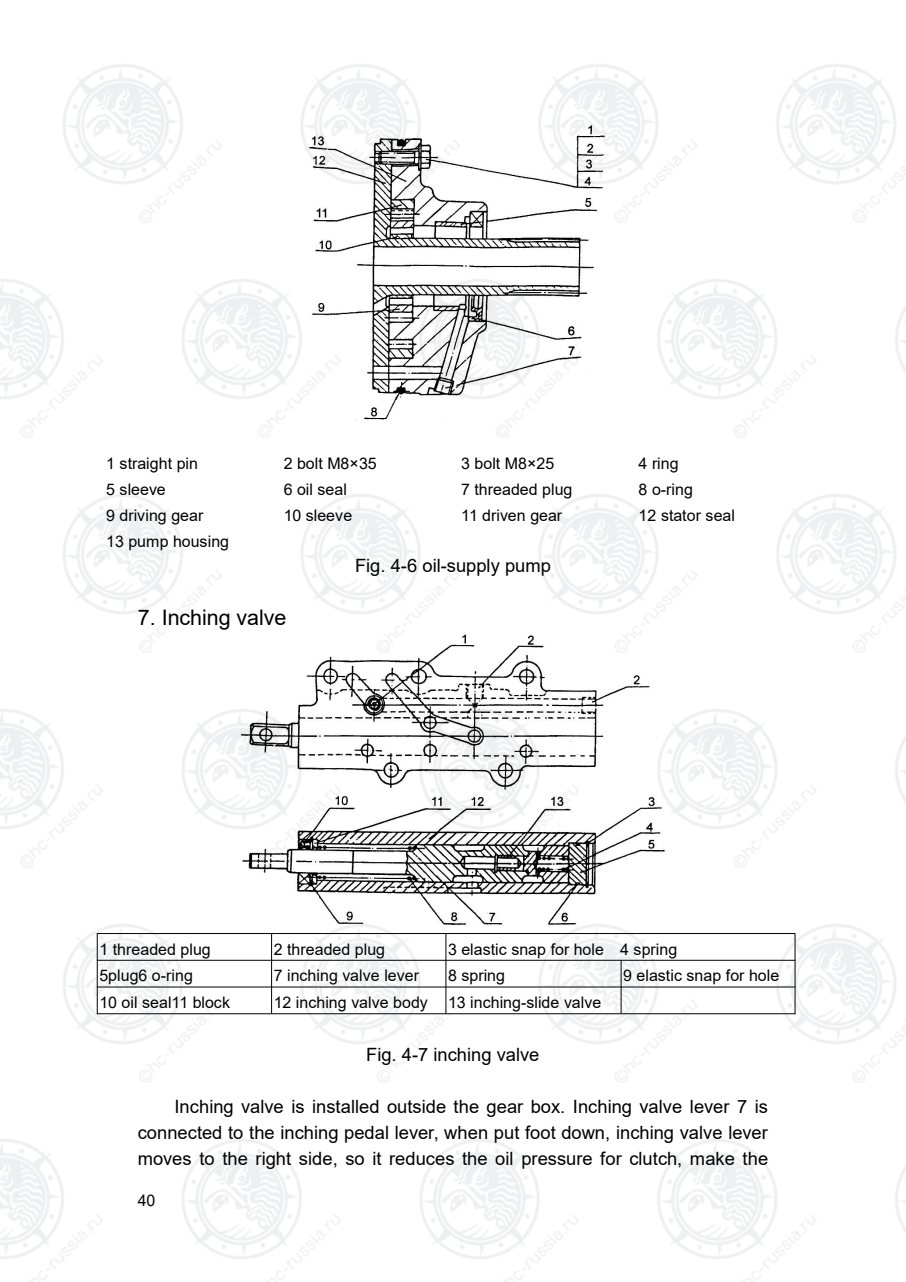
6. Oil-supply pump (Refer to fig.4-6)
Oil-supply pump is installed on the torque converter body. Driving gear 9
is connected to the impeller wheel, driven by engine, it mesh with the driven
gear 11 and supply oil for the torque converter、hydrodynamic gear box.
Оригинальная страница: таблицы и схемы
Страница 44
40
1 straight pin 2 bolt M8×35 3 bolt M8×25 4 ring
5 sleeve 6 oil seal 7 threaded plug 8 o-ring
9 driving gear 10 sleeve 11 driven gear 12 stator seal
13 pump housing
Fig. 4-6 oil-supply pump
7. Inching valve
1 threaded plug 2 threaded plug 3 elastic snap for hole 4 spring
5plug6 o-ring 7 inching valve lever 8 spring 9 elastic snap for hole
10 oil seal11 block 12 inching valve body 13 inching-slide valve
Fig. 4-7 inching valve
Inching valve is installed outside the gear box. Inching valve lever 7 is
connected to the inching pedal lever, when put foot down, inching valve lever
moves to the right side, so it reduces the oil pressure for clutch, make the
Оригинальная страница: таблицы и схемы
Страница 45
41
truck inching moving by slide the clutch disc.
8. Case and control valve
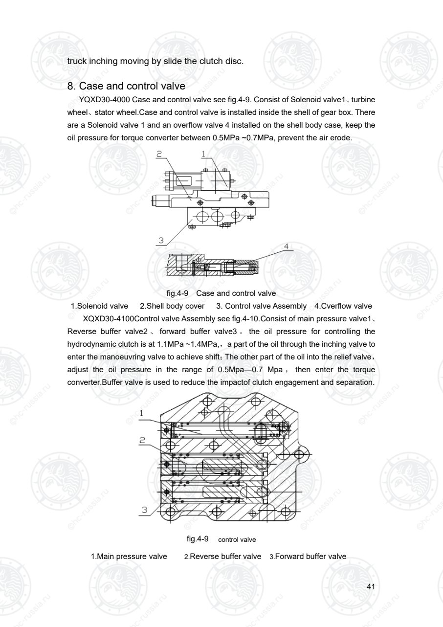
YQXD30-4000 Case and control valve see fig.4-9. Consist of Solenoid valve1、turbine
wheel、stator wheel.Case and control valve is installed inside the shell of gear box. There
are a Solenoid valve 1 and an overflow valve 4 installed on the shell body case, keep the
oil pressure for torque converter between 0.5MPa ~0.7MPa, prevent the air erode.
fig.4-9 Case and control valve
1.Solenoid valve 2.Shell body cover 3. Control valve Assembly 4.Cverflow valve
XQXD30-4100Control valve Assembly see fig.4-10.Consist of main pressure valve1、
Reverse buffer valve2 、 forward buffer valve3 。 the oil pressure for controlling the
hydrodynamic clutch is at 1.1MPa ~1.4MPa,,a part of the oil through the inching valve to
enter the manoeuvring valve to achieve shift;The other part of the oil into the relief valve,
adjust the oil pressure in the range of 0.5Mpa―0.7 Mpa , then enter the torque
converter.Buffer valve is used to reduce the impactof clutch engagement and separation.
fig.4-9 control valve
1.Main pressure valve 2.Reverse buffer valve 3.Forward buffer valve
Оригинальная страница: таблицы и схемы
Страница 46
42
9. Gear-box shell body
Gear box body plays the same role as tank besides used for installs the input and
output shaft, the oil strainerⅠ(150) in the bottom of it, filtrate the oil flowing to the
oil-supply pump, pipe oil strainerⅡ、 oil-add cover and oil leveler on the top of the
shell-body cover.
10. Reduction transmission and differentials
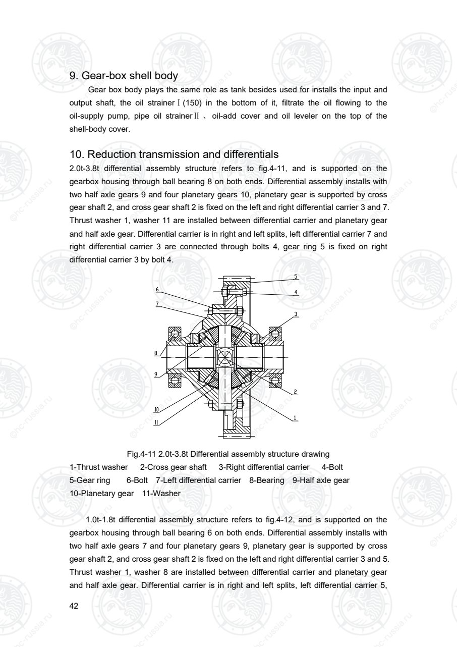
2.0t-3.8t differential assembly structure refers to fig.4-11, and is supported on the
gearbox housing through ball bearing 8 on both ends. Differential assembly installs with
two half axle gears 9 and four planetary gears 10, planetary gear is supported by cross
gear shaft 2, and cross gear shaft 2 is fixed on the left and right differential carrier 3 and 7.
Thrust washer 1, washer 11 are installed between differential carrier and planetary gear
and half axle gear. Differential carrier is in right and left splits, left differential carrier 7 and
right differential carrier 3 are connected through bolts 4, gear ring 5 is fixed on right
differential carrier 3 by bolt 4.
Fig.4-11 2.0t-3.8t Differential assembly structure drawing
1-Thrust washer 2-Cross gear shaft 3-Right differential carrier 4-Bolt
5-Gear ring 6-Bolt 7-Left differential carrier 8-Bearing 9-Half axle gear
10-Planetary gear 11-Washer
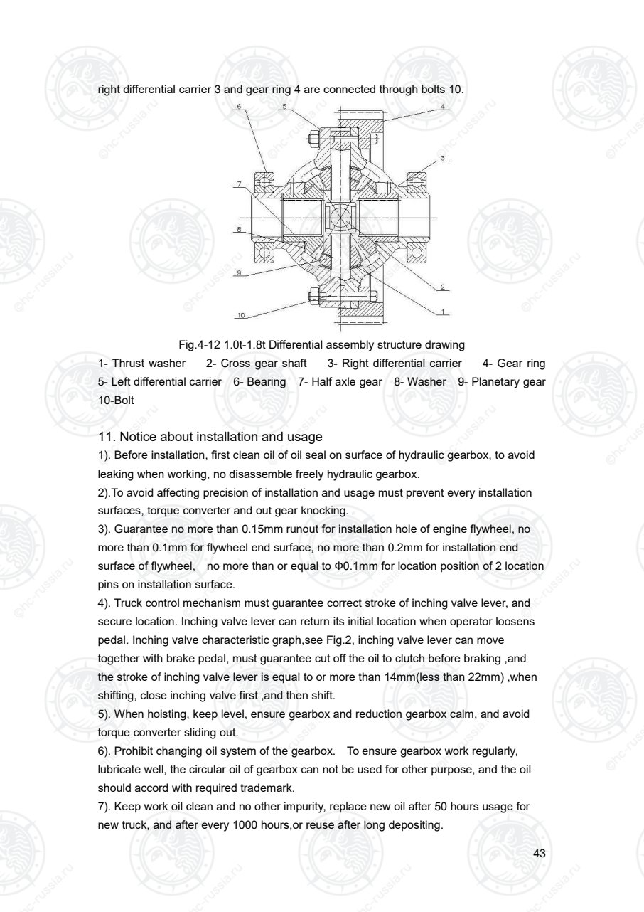
1.0t-1.8t differential assembly structure refers to fig.4-12, and is supported on the
gearbox housing through ball bearing 6 on both ends. Differential assembly installs with
two half axle gears 7 and four planetary gears 9, planetary gear is supported by cross
gear shaft 2, and cross gear shaft 2 is fixed on the left and right differential carrier 3 and 5.
Thrust washer 1, washer 8 are installed between differential carrier and planetary gear
and half axle gear. Differential carrier is in right and left splits, left differential carrier 5,
Оригинальная страница: таблицы и схемы
Страница 47
43
right differential carrier 3 and gear ring 4 are connected through bolts 10.
Fig.4-12 1.0t-1.8t Differential assembly structure drawing
1- Thrust washer 2- Cross gear shaft 3- Right differential carrier 4- Gear ring
5- Left differential carrier 6- Bearing 7- Half axle gear 8- Washer 9- Planetary gear
10-Bolt
11. Notice about installation and usage
1). Before installation, first clean oil of oil seal on surface of hydraulic gearbox, to avoid
leaking when working, no disassemble freely hydraulic gearbox.
2).To avoid affecting precision of installation and usage must prevent every installation
surfaces, torque converter and out gear knocking.
3). Guarantee no more than 0.15mm runout for installation hole of engine flywheel, no
more than 0.1mm for flywheel end surface, no more than 0.2mm for installation end
surface of flywheel, no more than or equal to Ф0.1mm for location position of 2 location
pins on installation surface.
4). Truck control mechanism must guarantee correct stroke of inching valve lever, and
secure location. Inching valve lever can return its initial location when operator loosens
pedal. Inching valve characteristic graph,see Fig.2, inching valve lever can move
together with brake pedal, must guarantee cut off the oil to clutch before braking ,and
the stroke of inching valve lever is equal to or more than 14mm(less than 22mm) ,when
shifting, close inching valve first ,and then shift.
5). When hoisting, keep level, ensure gearbox and reduction gearbox calm, and avoid
torque converter sliding out.
6). Prohibit changing oil system of the gearbox. To ensure gearbox work regularly,
lubricate well, the circular oil of gearbox can not be used for other purpose, and the oil
should accord with required trademark.
7). Keep work oil clean and no other impurity, replace new oil after 50 hours usage for
new truck, and after every 1000 hours,or reuse after long depositing.
Оригинальная страница: таблицы и схемы
Страница 48
44
8). Fill in work oil, run at neutral shift for5 minutes, then check oil height, and the height
should be within the specified range.
9). New hydraulic gearbox should breaking in 50 hours after it is installed,and the load is
no more than 70% in breaking in process, note oil temperature ,oil pressure and bolts
loosen or not usually, replace new oil after breaking in .
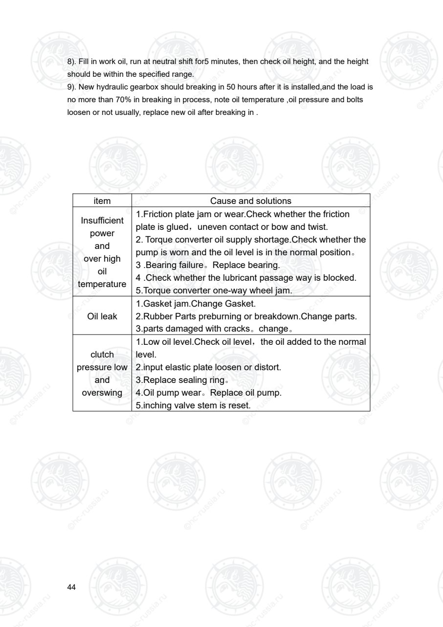
item Cause and solutions
Insufficient
power
and
over high
oil
temperature
1.Friction plate jam or wear.Check whether the friction
plate is glued,uneven contact or bow and twist.
2. Torque converter oil supply shortage.Check whether the
pump is worn and the oil level is in the normal position。
3 .Bearing failure。Replace bearing.
4 .Check whether the lubricant passage way is blocked.
5.Torque converter one-way wheel jam.
Oil leak
1.Gasket jam.Change Gasket.
2.Rubber Parts preburning or breakdown.Change parts.
3.parts damaged with cracks。change。
clutch
pressure low
and
overswing
1.Low oil level.Check oil level,the oil added to the normal
level.
2.input elastic plate loosen or distort.
3.Replace sealing ring。
4.Oil pump wear。Replace oil pump.
5.inching valve stem is reset.
Оригинальная страница: таблицы и схемы
Страница 49
45
Ⅴ. XYQXF Hydraulic transmission and torque
converter
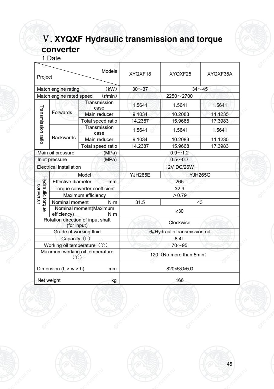
1.Date
Models
Project XYQXF18 XYQXF25 XYQXF35A
Match engine rating (kW) 30~37 34~45
Match engine rated speed (r/min) 2250~2700
Transmissionratio
Forwards
Transmission
case 1.5641 1.5641 1.5641
Main reducer 9.1034 10.2083 11.1235
Total speed ratio 14.2387 15.9668 17.3983
Backwards
Transmission
case 1.5641 1.5641 1.5641
Main reducer 9.1034 10.2083 11.1235
Total speed ratio 14.2387 15.9668 17.3983
Main oil pressure (MPa) 0.9~1.2
Inlet pressure (MPa) 0.5~0.7
Electrical installation 12V·DC/26W
Hydraulictorque
converter
Model YJH265E YJH265G
Effective diameter mm 265
Torque converter coefficient ≥2.9
Maximum efficiency >0.79
Nominal moment N·m 31.5 43
Nominal moment(Maximum
efficiency) N·m ≥30
Rotation direction of input shaft
(for input) Clockwise
Grade of working fluid 6#Hydraulic transmission oil
Capacity(L) 8.4L
Working oil temperature(℃) 70~95
Maximum working oil temperature
(℃) 120(No more than 5min)
Dimension (L × w × h) mm 820×530×500
Net weight kg 166
Оригинальная страница: таблицы и схемы
Страница 50
46
2.Summary
XYQXF18/25/35A floating hydraulic transmission is composed of hydraulic
transmission, airfoil coupling and main reducer.
Hydraulic transmission is composed of hydraulic torque converter and hydraulic shift
transmission.
The torque converter used in the hydraulic transmission is a single-stage, two-phase
and three wheel integrated torque converter. The hydraulic torque converter makes the
hydraulic transmission have the automatic adaptability of hydraulic transmission output,
which can change its output torque and speed with the change of external load, and can
absorb and eliminate the impact and vibration from the engine and external load on the
transmission system.
Hydraulic shift transmission is a power shift transmission with front and back gears.
The shift mode is electromagnetic control power shift, and it is equipped with micro valve
and buffer valve, which makes the operation simple, convenient and stable, and greatly
reduces the labor intensity of the operator.
The main reducer consists of a two-stage reducer and a differential assembly. The
two-stage reducer is composed of a pair of cylindrical gears (one-stage reducer) and a
pair of spiral bevel gears (two-stage reducer), which is simple in structure and easy to
maintain.
The differential assembly is composed of four planetary gears and two half shaft
gears. The half shaft is driven by the half shaft gear to drive the tire and realize the power
output.
The hydraulic transmission is connected with the main reducer through the airfoil
coupling, and the power of the engine is transmitted to the wheels through the hydraulic
transmission → airfoil coupling → main reducer, so as to realize the flexible transmission.
The hydraulic transmission and the engine are supported on the frame and the
bridge through the cushion, which can effectively reduce the damage of the vehicle
vibration to the engine and the transmission, protect the transmission and the engine,
and reduce the impact of the vibration when the engine is running on the whole vehicle,
so as to improve the driving comfort of the whole vehicle.
Оригинальная страница: таблицы и схемы
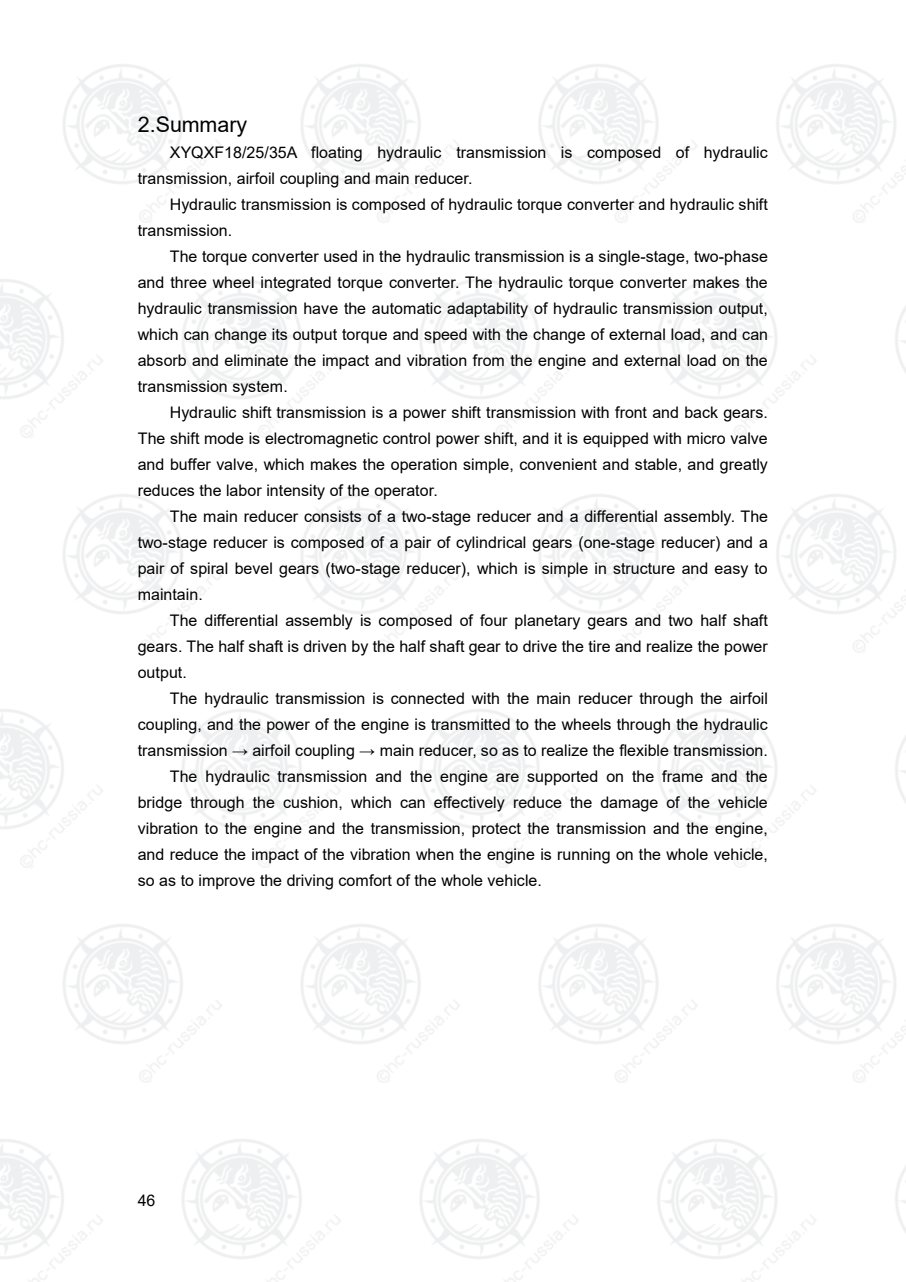
Страница 51
47
3.Working principle and internal structure
3.1 Working principle
3.1.1、Transmission principle
The transmission diagram of the hydraulic transmission gearbox is shown in Figure
5-1. The hydraulic torque converter is driven by the engine through the elastic coupling
plate 1, which drives the pump wheel 4 to rotate, so that the liquid flow flows into the
turbine 2 at high speed along its blade direction, and drives the turbine to rotate. The
guide wheel 3 causes the torque converter to change torque and transmit torque to the
input shaft assembly 10 of the hydraulic transmission through the turbine shaft 5.
When the forward gear is engaged, the reverse clutch idles, and the transmission
sequence is part 10 → Part 7 → Part 12 → Part 11 → Part 14 → Part 15 → Part 16 →
Part 17 → Part 18 → Part 19, driving the output of differential 20.
Fig 5-1 XYQXF18/25/35 Transmission diagram of hydraulic transmission
1.Elastic connection plate 2. Turbine 3. Guide wheel
4. Pump wheel 5. Turbine shaft 6. Oil pump 7. Clutch gear
8. Friction plate 9. Spacer 10. Input shaft assembly (forward clutch)
11. Output flange 12. Output gear 13. Intermediate shaft assembly (reverse
clutch)
14.Universal coupling 15. Input flange 16. Driving gear 17. Driven gear
18. Driving spiral bevel gear 19. Driven spiral bevel gear
20. Differential 21. Half shaft gear Planetary gear
Hydraulic transmission
输出
输出
Main reducer
Input
Оригинальная страница: таблицы и схемы
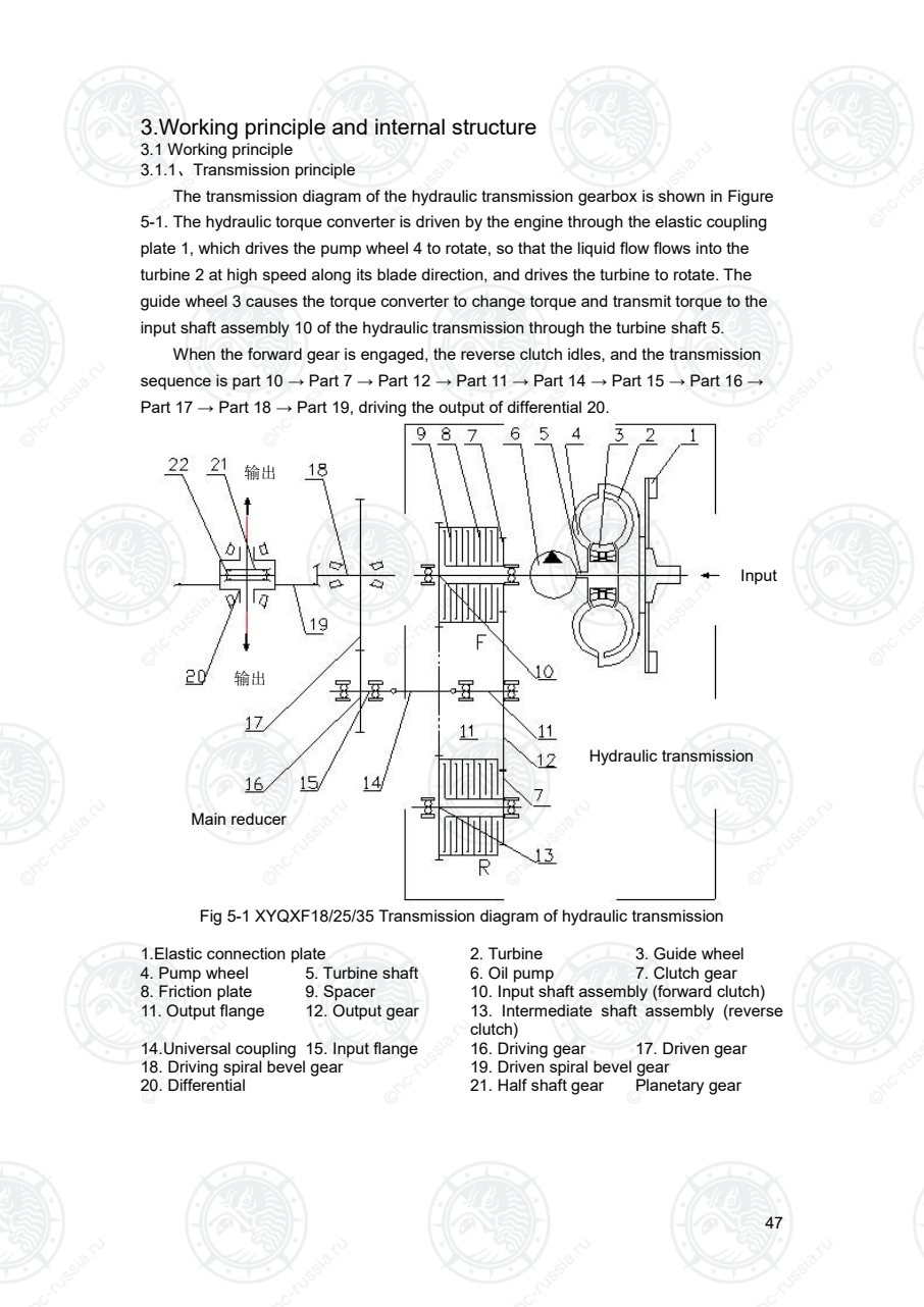
Страница 52
48
When the reverse gear is engaged, the forward clutch idles, and the transmission
sequence is part 10 → Part 13 → Part 7 → Part 11 → Part 14 → Part 15 → Part 16 →
Part 17 → Part 18 → Part 19, which drives the output of differential 20.
The forward and reverse clutches are controlled by an electromagnetic power shift
control valve. The oil pump 6 is an internal gear pump, which is directly driven by the
engine through the pump wheel. The oil pump provides pressure oil to the system. After
the hydraulic torque converter works, the oil enters the radiator on the vehicle, and then
enters the gearbox to lubricate the friction plate, bearing and gear.
3.1.2、Hydraulic principle
The oil circuit schematic diagram of XYQXF18/25/35 hydraulic transmission is
shown in Figure 5-2, in which F represents forward gear and R represents backward
gear.
1
2
3
4 12
13
16
14
3 8 15
0.3
0.5
1.0
1.3
20
40
50
MPa N
mm
5
6 7
8
9 10
15
11
Fig 5-2 Oil circuit schematic diagram of XYQXF18/25/35 hydraulic transmission
1.Oil tank 2.Coarse filter 3.Oil supply pump 4.Fine filter
5.φ 1.3 orifice 6.Micro valve 7.φ 1.4 compensation hole
8.Compensation on-off 9.Accumulator
10.Electromagnetic directional valve 11.Shuttle valve
12.Main pressure valve 13.Torque converter 14.Relief valve
15.φ 3 pressure relief hole 16. Car cooler
After the engine starts, the supply pump 3 draws oil from the transmission oil tank 1
through the primary filter 2. After the oil passes through the fine filter 4, it enters the main
pressure valve 12 and the oil is divided into two parts. A part of the oil passes through the
torque converter relief valve 14 and then enters the torque converter 13. After the torque
converter runs, it enters the vehicle cooler 16 and enters the transmission lubricating oil
circuit after cooling, There is a φ 3 pressure relief hole between the inlet and outlet of the
Fretting
characteristiccurve
Tension curve of
fretting valve stem
To lubricating oil circuit
Оригинальная страница: таблицы и схемы
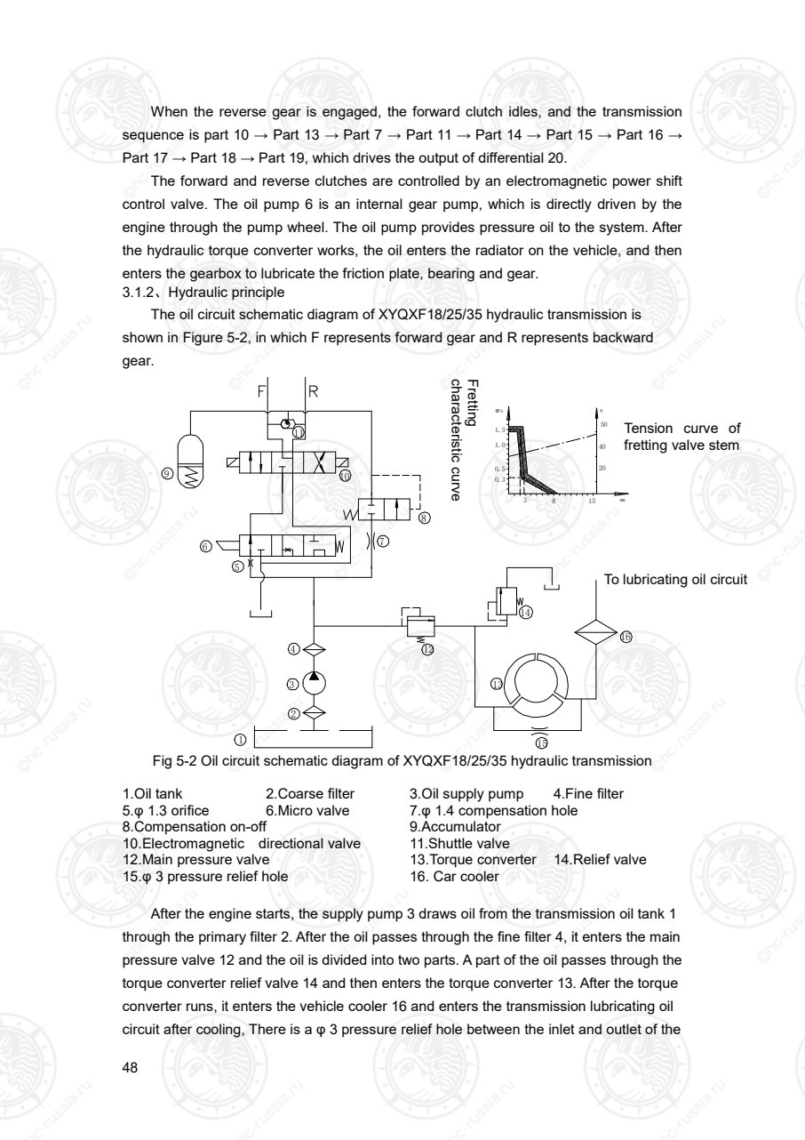
Страница 53
49
torque converter to ensure that the pressure of the torque converter is too high
instantaneously during the cold start of the vehicle, and the lubricating oil quantity of the
whole vehicle can be ensured when the torque converter relief valve is opened.
The other part enters the micro valve 6 through the orifice 5. When the micro pedal is
not pressed, the oil flows through the micro valve and enters the electromagnetic
directional valve 10. According to the electric signal given by the combination switch of
the whole vehicle, the electromagnetic directional valve controls the oil flow to the R, F or
neutral position (the oil flows directly into the oil tank in neutral position). When the micro
pedal is pressed, the oil directly enters the oil tank from the micro valve, and the clutch
pressure oil is cut off.
When the vehicle is in forward gear, shuttle valve 11 will move backward, and the oil
port will disconnect the oil circuit between accumulator 9 and backward gear, so as to
connect the oil circuit between forward gear and accumulator. It can effectively slow down
the rising speed of clutch pressure and reduce the impact. When the clutch pressure
reaches a certain value, the compensation on-off valve 8 is opened, and the pressure oil
enters the clutch through the compensation hole 7, the clutch can reach the working
pressure more quickly and improve the vehicle reaction speed. The accumulator and
compensation on-off valve constitute the buffer valve. On the contrary, when the vehicle
is put into reverse gear, the accumulator is connected with the oil circuit of reverse gear,
which plays a buffer role.
3.2 Structure introduction
3.2.1、Structure introduction
The structural diagram of XYQXF18/25/35 hydraulic transmission is shown in Figure
5-3. The power of the engine is input to the input shaft assembly 8 of the transmission by
the torque converter turbine through the spline connection through the torque converter
6.
The gearbox is mainly composed of input shaft assembly 8, intermediate shaft
assembly 5, output gear 2, output flange 1, electromagnetic directional control valve
assembly 9, oil supply pump assembly 7 and other main parts. The forward or backward
clutch is controlled by the electromagnetic reversing control valve to realize reversing,
and the power is transmitted to the universal coupling through the output gear and output
flange.
Оригинальная страница: таблицы и схемы
Страница 54
50
Fig 5-3 Structural diagram of XYQXF18/25/35hydraulic transmission
1.Housing assembly 2.Output gear 3.Output flange
4.Torque converter housing assembly 5.Intermediate shaft assembly
6.Torque converter assembly 7.Oil pump assy 8.Input shaft assy
9. Solenoid control valve assembly 10. Bracket 11.Reducer assy
12.Input flange 13.Driving gear 14.Differential assy 15.Driven gear
16.Driven spiral bevel gear 17.Driving spiral bevel gear
18.Lock nut 19.End cover 20.Differential cover 21.Differential seat
22.Universal coupling assembly
The reducer is mainly composed of input flange 12, driving gear 13, driven gear 15,
driving spiral bevel gear 17, driven spiral bevel gear 16 and differential assembly 14. The
power from the gearbox is transmitted to the input flange by the universal coupling 22.
After two-stage deceleration, the differential drive is generated by the differential and
transmitted to the wheel through the half shaft gear and the half shaft.
At the same time, the gearbox and reducer itself also play the role of fuel tank. The
transmission and the reduction box are fixedly connected by a damping bracket 10.
Оригинальная страница: таблицы и схемы
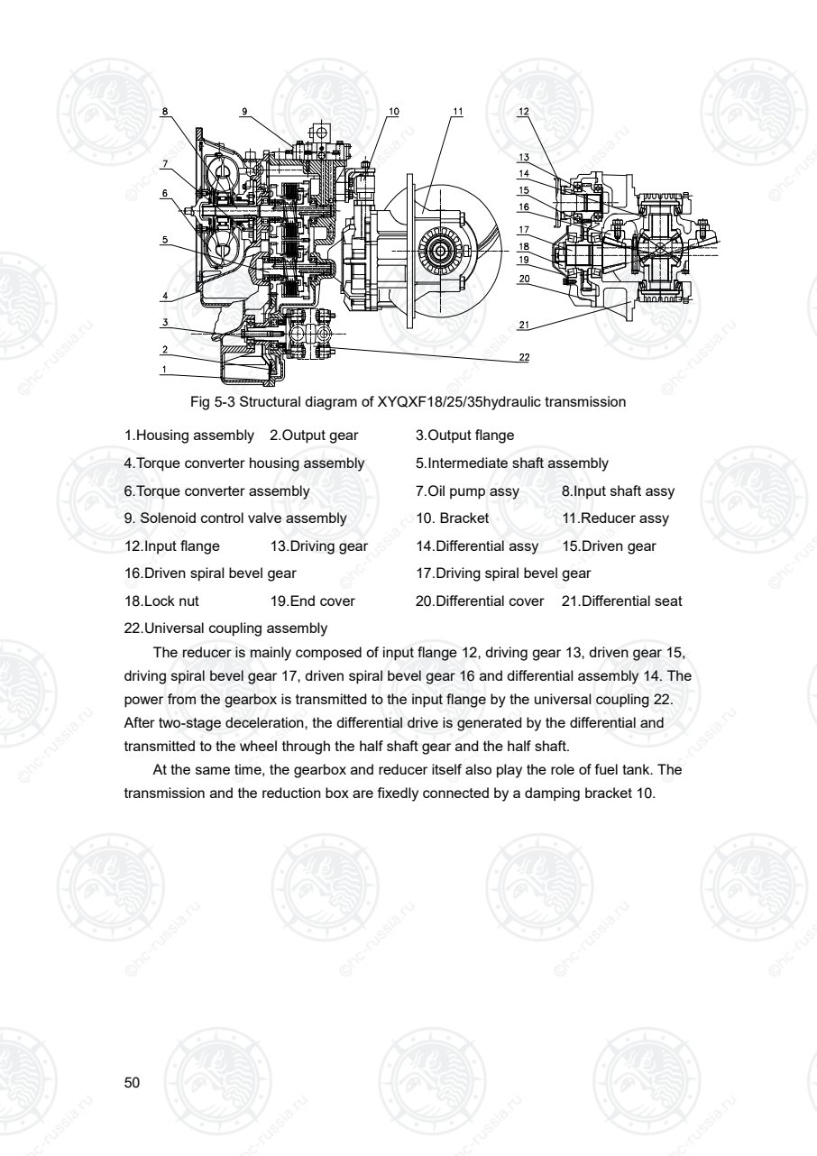
Страница 55
51
3.2.2、Hydraulic torque converter
The torque converter used in XYQX18/25/35 hydraulic transmission is welding type,
which cannot be disassembled. See Figure 5-4 for the structural diagram of the torque
converter.
Fig 5-4 Structural diagram of hydraulic torque converter
1. Clutch 2. One way clutch 3. Pump wheel 4. Guide wheel
5. Turbine 6 - elastic connecting plate
The torque converter is mainly composed of pump wheel, turbine, guide wheel and
elastic connecting plate. The elastic plate 6 is directly connected to the engine flywheel.
The pump wheel 3 converts the mechanical energy of the engine into the kinetic energy
of the working oil through the elastic plate, and makes the liquid flow flow into the turbine
5 at high speed along the direction of the blade, which drives the turbine to rotate, and the
torque and speed are transmitted to the gearbox by the turbine shaft. The liquid flows out
of the turbine and into the guide wheel 4. When the torque converter is under a large load,
the turbine is affected by the load, and is in the torque conversion stage of low speed and
high torque, the guide wheel is wedged by the one-way clutch 2 and cannot rotate, and
the torque of the liquid flow acting on the guide wheel is reversed on the turbine, so that
the torque on the turbine is equal to the sum of the torque of the pump wheel and the
guide wheel, so the output torque is greater than the input torque, resulting in automatic
torque conversion When the ratio of rotor speed to pump speed is greater than a certain
value, the guide wheel will be disengaged and rotate freely, and the torque conversion
will be terminated, which is a coupled state.
Оригинальная страница: таблицы и схемы
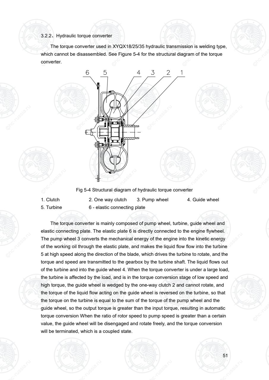
Страница 56
52
When the engine starts, the speed of the pump wheel is synchronized with that of the
engine, and the pump wheel drives the gearbox to supply the oil pump through the clutch
to provide pressure oil for the system.
3.2.3、Oil supply pump assembly
The structural diagram of XYQXF35-3000 oil supply pump assembly is shown in Figure 5-5.
The oil supply pump assembly is mainly composed of driving gear 1, guide wheel seat 2, passive
gear 3, pump body 4 and other parts. The oil supply pump assembly is installed on the torque
converter housing. The guide wheel seat 2 is connected with the torque converter guide wheel
through splines. The pump body 4 is a casting with high-pressure cavity and low-pressure cavity.
The driving gear 1 is connected with the torque converter pump wheel, which is driven by the
engine and drives the passive gear 3 to rotate to form internal gear The pump supplies oil to the
system.
Fig 5-5 Structural diagram of xyqxf35-3000 oil pump assembly
1. Driving gear 2. Guide wheel seat 3. Driven gear 4. Pump body
3.2.4、Control valve assembly
The oil port location of XYQXF35-4100 control valve is shown in Figure 5-6.
XYQXF35-4100 control valve is a comprehensive integrated valve block with high
integration, compact space structure and reasonable layout. It is mainly composed of
micro valve, buffer valve and shuttle valve.
The structure of the micro valve is shown in A-A. the micro valve is mainly used to
cut off the oil inlet of the clutch. The fretting valve rod is connected to the connecting rod
of the fretting pedal. When the fretting pedal is depressed, the fretting valve rod moves
outward. When the fretting valve rod moves outward by 2mm, the fretting valve rod
moves outward by 2mm, The clutch begins to depressurize, and when the clutch
pressure drops to a certain pressure, the friction plate slips, which makes the vehicle
achieve fretting effect; when the fretting valve rod moves 8 mm outward, the clutch
pressure drops to 0, the clutch friction plate and the spacer can not be combined, and the
vehicle stops moving; when the fretting valve rod moves 12 mm outward, the travel of the
Оригинальная страница: таблицы и схемы
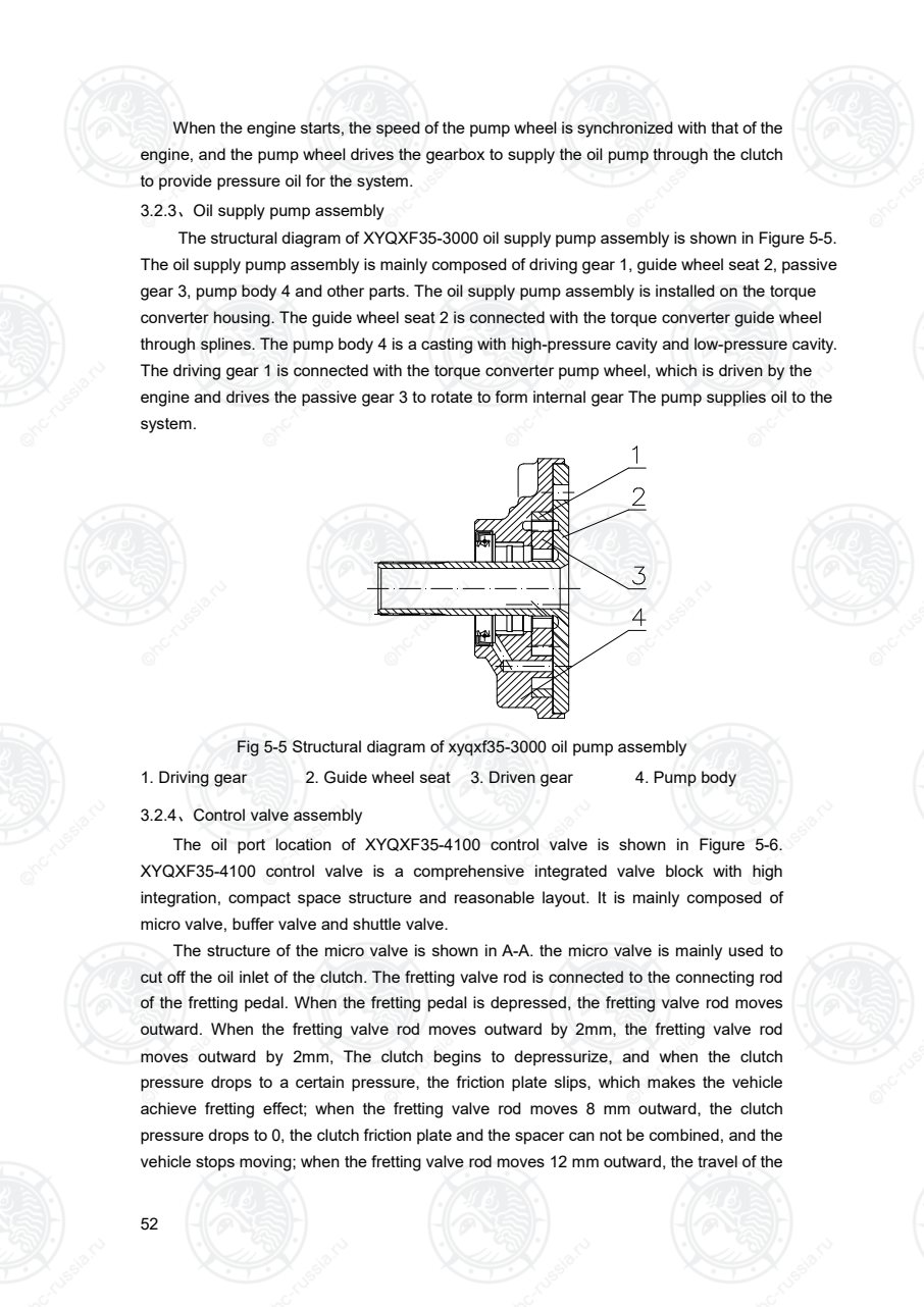
Страница 57
53
fretting valve rod stops.
Fig 5-6 XYQXF35-4100 control valve assembly
The structural diagram of buffer valve is shown in B-B. the buffer valve is used to
reduce the impact produced in the process of clutch combination and separation.
The shuttle valve structure diagram is shown in d-d. according to the control of the
solenoid valve, the shuttle valve can introduce the oil of the buffer valve into the forward
clutch or reverse clutch to make the buffer valve play a buffer role.
1.Damping plug 2.Plug 3.Control valve core 4.Control spring
5. Micro valve core 6. Return spring 7.Buffer spring 8.Limit post
9.Buffer spool 10.Shuttle spool
Оригинальная страница: таблицы и схемы
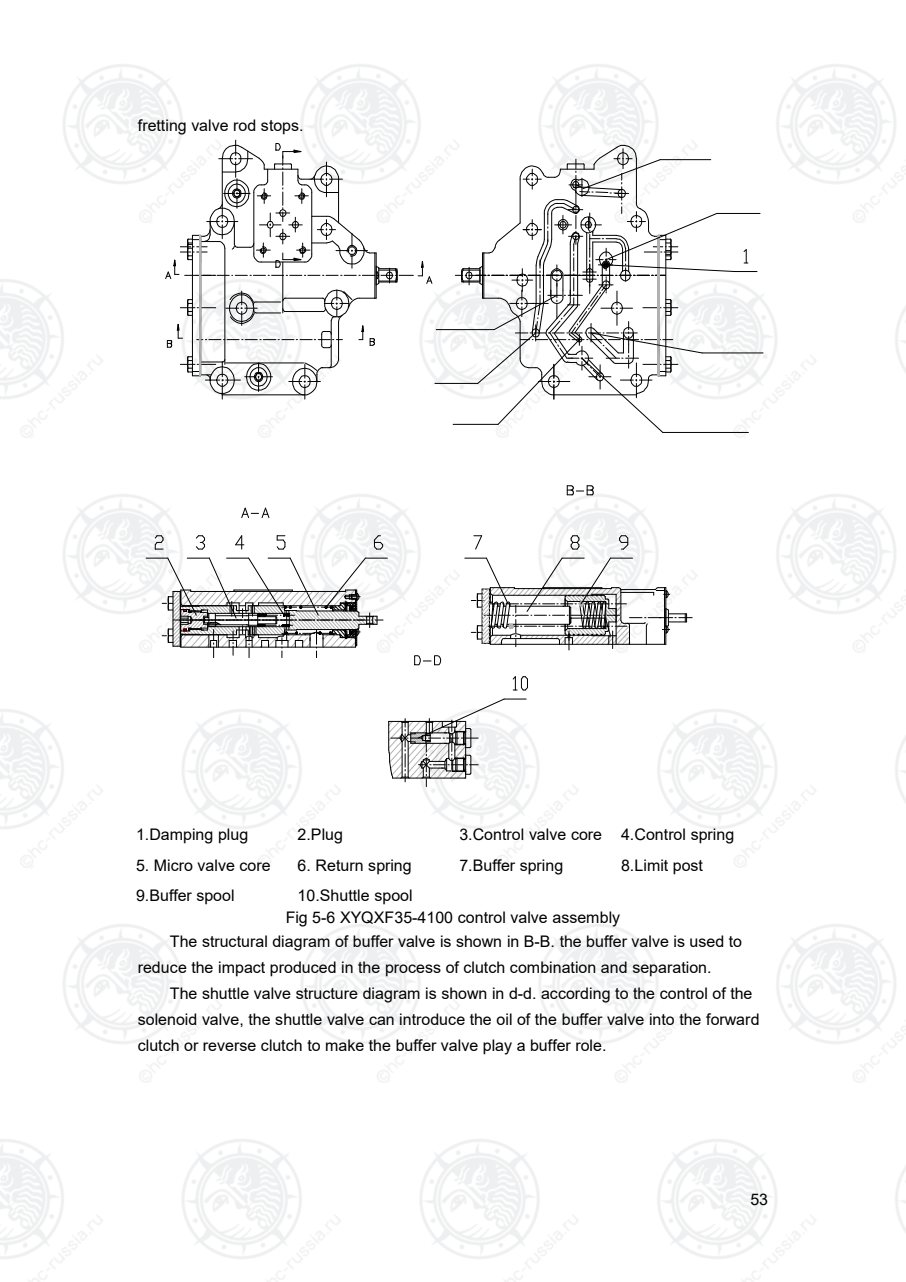
Страница 58
54
3.2.5、Main pressure valve, relief valve
See Figure 5-7 for the structural diagram of the main pressure regulating valve
assembly. The main pressure regulating valve controls the clutch oil pressure in the
range of 1.1mpa-1.5mpa. A part of the oil flows into the electromagnetic directional
control valve to realize the shift; a part of the oil flows into the relief valve.
图6  主调压阀结构图Fig 5-7 structural diagram of main pressure regulating valve
1.Valve body 2.Valve cor 3.Screw plug 4.Main pressure regulating valve
spring
5.Sealing ring 6. Screw plug
The structural diagram of relief valve assembly is shown in Figure 5-8. Relief valve
is also known as torque converter safety valve. The relief valve controls the oil pressure
within the range of 0.3mpa-0.7mpa to flow into the torque converter.
图7  变矩器安全阀(益流阀)结构图Fig 5-8 Structural diagram of relief valve
1.Valve body 2.Spring 3.Valve core
Оригинальная страница: таблицы и схемы
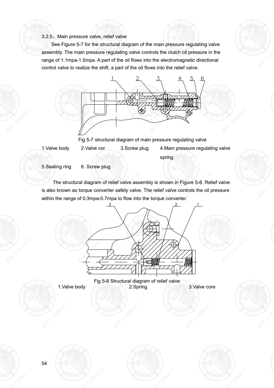
Страница 59
55
3.2.6、Clutch
The wet multi plate hydraulic clutch is installed on the input shaft and intermediate
shaft of the hydraulic transmission, and the pressure oil is distributed to the forward or
backward clutch through the control valve to realize the forward and backward shift. All
gears in the gearbox are constant mesh gears.
Each clutch of the clutch assembly is composed of five spacer plates 18, five friction
plates 19, a backing plate 14, a butterfly plate 21 and a piston 2, which are assembled
alternately.
The outer circle of the piston is equipped with piston ring 17, and the input shaft is
equipped with O-ring 3, so as to ensure the sealing of the piston when it works. In neutral
position, the piston does not move, and the spacer and friction plate are separated. When
shifting, the oil pressure acts on the piston, the spacer and the friction plate to compress
each other, and the power from the torque converter is transmitted to the clutch gear by
the friction force.
Fig 5-9 YQXF35-1000 input shaft/YQXF35-5000 intermediate shaft clutch assembly
1.Input shaft assy 2.Clutch gear 3.Bearing 4.Spacer
5.Bearing 6.Retaining ring 7.Retaining rin 8.Spring seat
9.Spring 10.Clip 11.End plate 12.Internal friction plate
13.External friction 14.Base plate 15.Sealing ring 16.Piston ring
17.Piston 18.Sealing ring 19.Butterfly piece
Оригинальная страница: таблицы и схемы
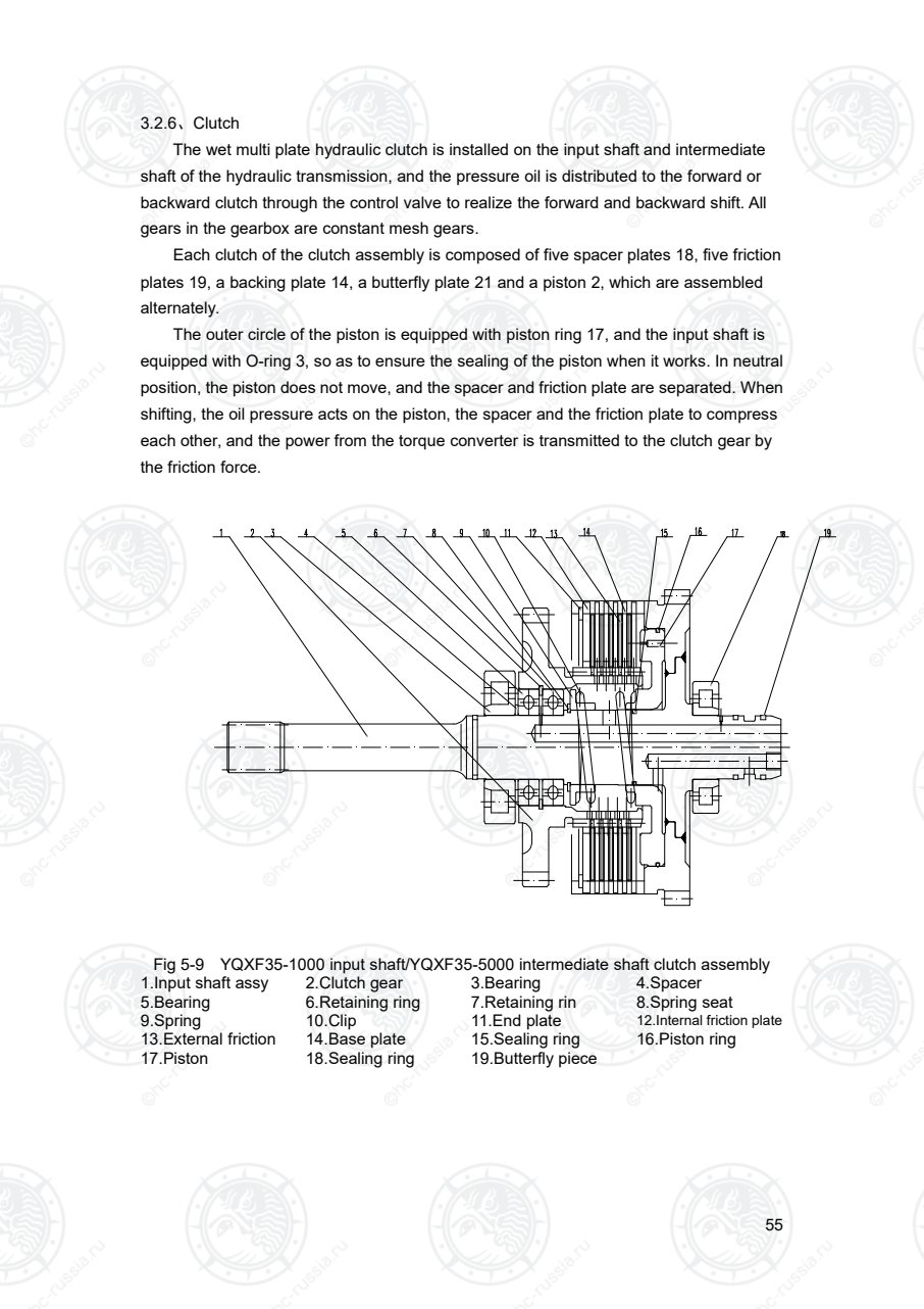
Страница 60
56
3.2.7、Reducer assembly
The structural diagram of the reducer assembly is shown in Figure 10. It is composed of a
pair of cylindrical gears and a pair of spiral bevel gears. The two-stage reducer and differential
are combined to form the reducer assembly. The reducer assembly is equipped with input flange
1, driving gear 2, driven gear 4, driving spiral bevel gear 7, driven spiral bevel gear 8, differential
seat assembly 9, differential cover 8, two axle gears 11, four planetary gears 14, cross shaft 12
and differential housing assembly 3. Thrust washer 15 and washer 10 are installed between
differential housing, planetary gear and half shaft gear.
The power from the gearbox is transmitted to the reducer through the input flange, and then
through the secondary reduction, the differential drive is generated by the differential, which is
transmitted to the wheel through the half shaft gear and the half shaft.
Fig 5-10 Structural diagram of reducer assembly
1-input flange 2-driving gear 3-differential housing assembly
4-driven gear 5-driven spiral bevel gear 6-adjusting pad
7-driving spiral bevel gear 8-differential cover 9-differential seat
10-washer 11-axle gear 12-cross shaft 13-adjusting nut
14-planetary gear 15-thrust washer
Оригинальная страница: таблицы и схемы
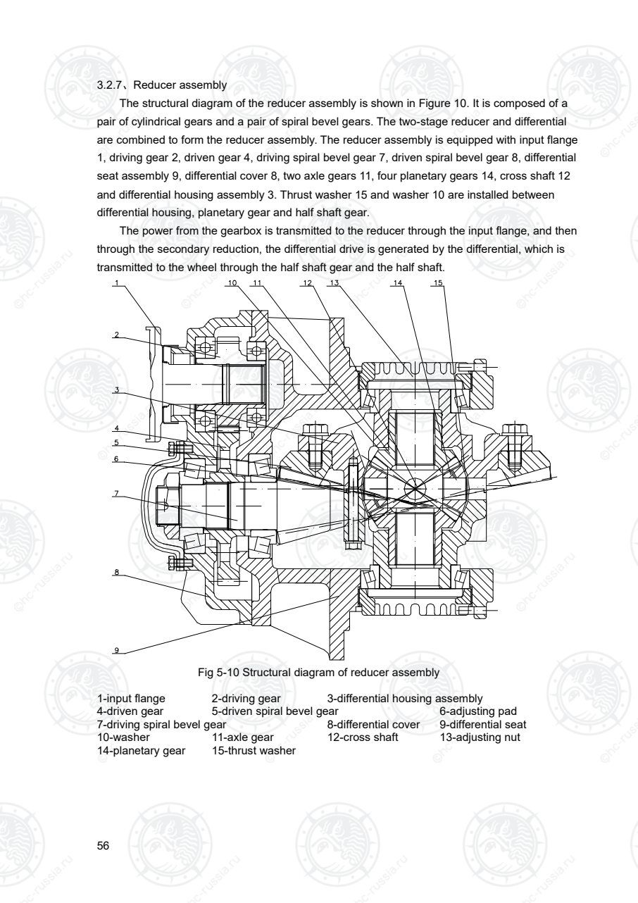
Страница 61
57
4.Maintenance and adjustment
4.1、Oil level check (engine idle speed check)
Stop the vehicle on a level road, inject oil, run in neutral for 2 minutes, and then
check the oil level of the oil dipstick. The oil level should be within the specified range of
the oil dipstick. If it does not meet the requirements, refuel or open the drain plug to drain
oil. The position of oil drain plug is shown in the figure below:
4.2、Change oil, check and clean filter screen
4.2.1、start the engine, run it for about ten minutes and stop it.
4.2.2、remove the drain plug to drain the oil. After draining the oil, tighten the oil drain
plug.
4.2.3、remove the fixing bolts, remove the oil filter seat, remove the primary filter and
clean the primary filter with cleaning agent. (Note: if the paper pad is damaged during
disassembly, clean the paper pad left on the joint surface and replace it with a new one).
Drain plug
Oil filter seat
Paper pad
Primary filter
Оригинальная страница: таблицы и схемы
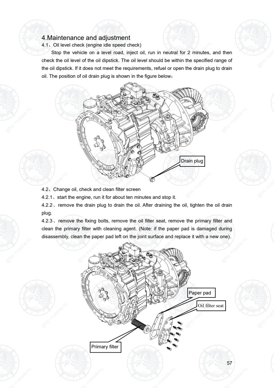
Страница 62
58
4.2.4、After cleaning, blow dry compressed gas from the inside to the outside of the
primary filter, and install when it is completely dry. Note: if any damage is found on the
primary filter, a new primary filter is required.
4.2.5、Remove the fine filter and replace it.
4.2.6、Refuel (according to the above 1).
4.2.7、After 100 hours of use of the new machine, the fine filter shall be replaced and the
coarse filter shall be cleaned; after 500 hours of use, the fine filter shall be replaced and
the coarse filter shall be cleaned; after 2000 hours of use, the coarse filter shall be
replaced.
Fine filter
Оригинальная страница: таблицы и схемы
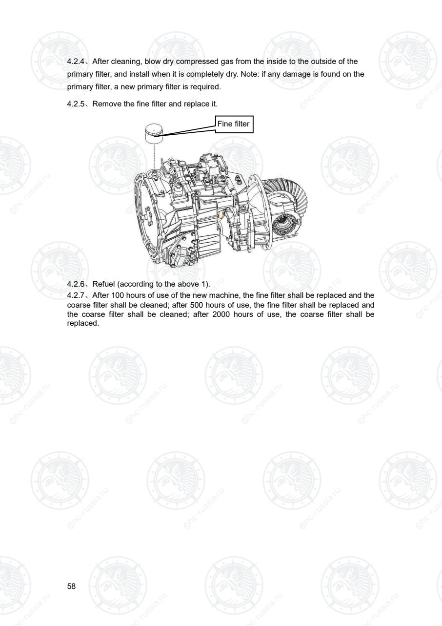
Страница 63
59
5.Disassembly and assembly
1、Gearbox disassembly and assembly
1.
Before disassembling the
gearbox, drain the residual oil
in the gearbox, and replace the
O-ring at the drain plug. After
drain the residual oil, screw the
drain plug 1 back to the
gearbox.
Parts description Characteristic requirements Tooling and tools
1-Oil drain plug + O-ring A.tightening torque 35-40N·m 10mm inner hexagon wrench
Оригинальная страница: таблицы и схемы
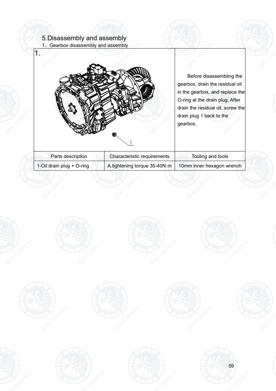
Страница 64
60
2.
Remove the bolt 4,
remove the dust cover,
remove the bolt 5, and then
remove the coupling 6. Then
remove the lock nut 9 and bolt
8, remove the cushion 7,
separate the main reducer
assembly 2 from the
transmission, and finally
remove the bolt 10 and the
bracket 11.
Parts description Characteristic requirements Tooling and tools
2-Final drive assembly
3-Dust cover
4-Bolt + spring pad (2 pieces) a、tightening torque 22-30N·m 13mm outer hexagon socket
5-Bolt + spring pad (8 pieces) a、tightening torque 70-80N·m 16mm outer hexagon socket
6-Coupling
7-Cushion
8-Bolt (2 pieces) a、tightening torque 160-180N·m 19mm outer hexagon socket
9-Nut + flat pad (2 pieces) a、tightening torque 95-105N·m 19mm outer hexagon socket
10-Bolt + spring pad (4 pieces) a、tightening torque 95-105N·m 19mm outer hexagon socket
11-Bracket
Оригинальная страница: таблицы и схемы
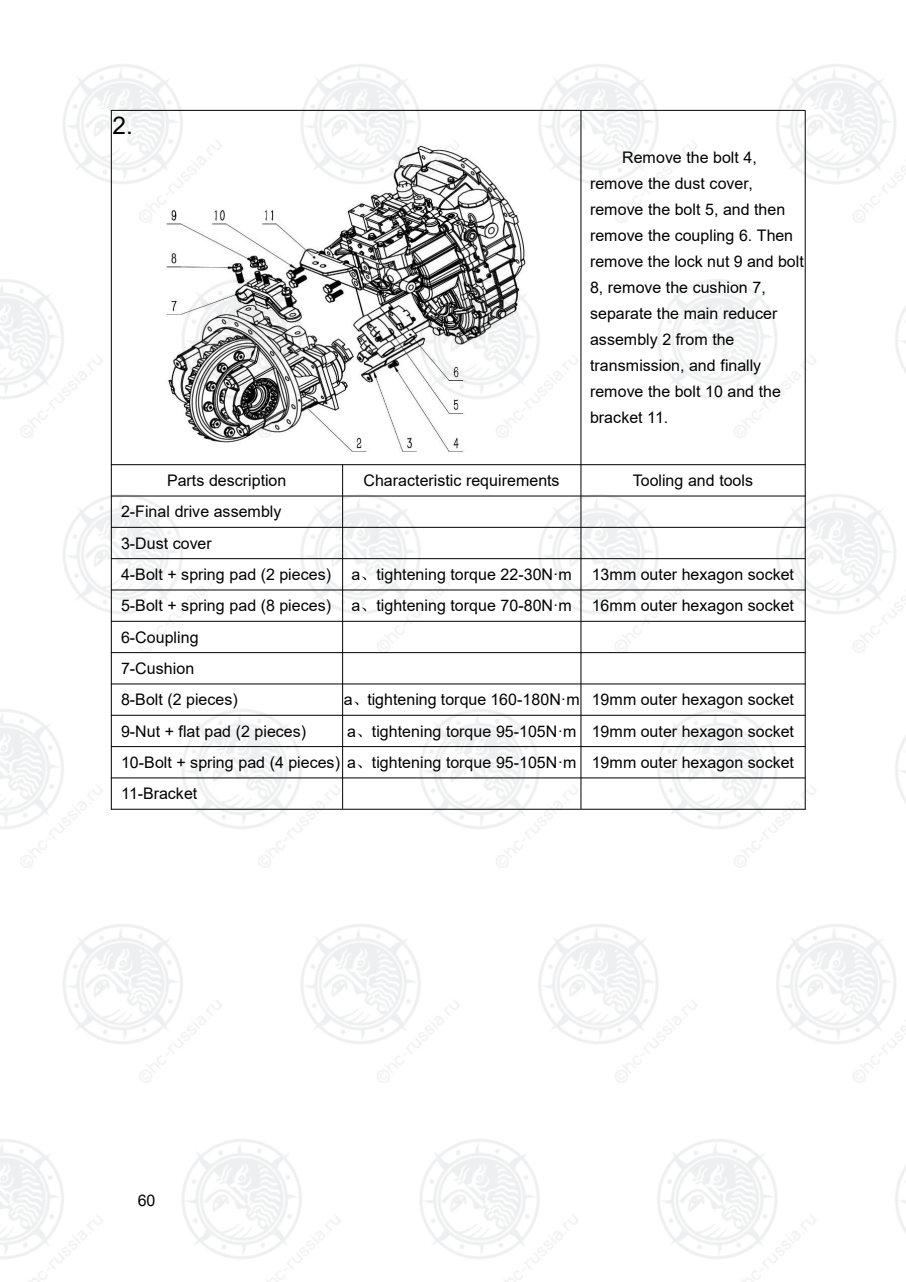
Страница 65
61
3.
Remove torque converter
assembly 12.
Parts description Characteristic requirements Tooling and tools
12-Torque converter assembly
During installation, push in
while rotating
4.
Remove the solenoid
valve 13. Pay attention to the
four O-rings at the bottom of
the solenoid valve. Remove
the mounting bolt 14, remove
the control valve assembly 15
and the paper pad 16. If the
paper pad is damaged during
installation, replace the paper
pad. At the same time, clean
up the residual paper pad on
the control valve surface and
box surface, and prevent the
paper pad debris from entering
the control valve and box hole.
Parts description Characteristic requirements Tooling and tools
13-Solenoid directional valve a、Tightening torque 8-10N·m 4mm hexagon wrench
14-Bolt + spring washer (8)
a、Tightening torque 22-30N·m
13mm outer hexagon socketb、Diagonal tightening is
required during installation
15-Control valve
16-Paper pad
a、Vulnerable parts (to be
replaced during disassembly)
Оригинальная страница: таблицы и схемы
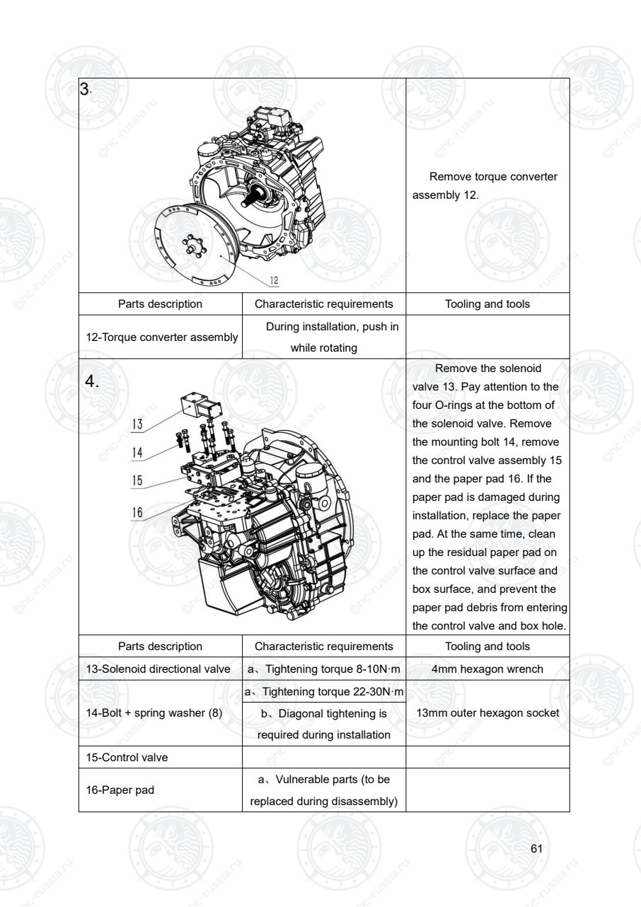
Страница 66
62
5.
Remove the fixing bolt 19,
take out the oil supply pump 18
and remove the O-ring 17.
Note that since the O-ring here
is a plane seal, the O-ring must
be replaced during installation,
and the O-ring is not allowed to
be reused.
Parts description Characteristic requirements Tooling and tools
17-O-ring
a、Vulnerable parts (to be
replaced during disassembly)
18-Oil pump assembly
19-Bolt + copper pad (5
pieces)
a、Tightening torque N·m
12mm Outer hexagon sleeveb、Diagonal tightening is
required during installation
6.
 Remove the bolt 20 and
take down the torque converter
housing assembly 21. During
installation, clean up the
residual sealant on the joint
surface of the torque converter
housing and the transmission
housing. At the same time,
apply a little anaerobic
adhesive plane glue on the
joint surface during installation.
Finally, remove dowel 23 and
O-ring 22. Note that as the
O-ring here is a plane seal, the
O-ring must be replaced during
installation, and the O-ring is
not allowed to be reused.
Parts description Characteristic requirements Tooling and tools
20-Bolt (18) a、Tightening torque N·m 15mmOuter hexagon sleeve
21-torque converter housing assy
22-Cylindrical locating pin
23-O-ring
a、Vulnerable parts (to be
replaced during disassembly)
Оригинальная страница: таблицы и схемы
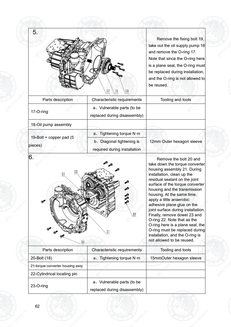
Страница 67
63
7.
Remove the bolt 29,
remove the oil shield, remove
the bolt 27, and then remove
the output flange 23. Remove
the bearing 26, output gear 25
and bearing 24 in turn.
Parts description Characteristic requirements Tooling and tools
23-Output flange assembly
24-Deep groove ball bearing
25-Output gear
26-Deep groove ball bearing
27-Bolt + washer A.Tightening torque 100-120N·m 18mm Outer hexagon sleeve
28-Oil shield
29-bolt + spring washer (4
pieces)
A.Tightening torque 13-16N·m 10mm Outer hexagon sleeve
8.
Remove input clutch
assembly 31 and reverse
clutch assembly 30.
Parts description Characteristic requirements Tooling and tools
30-Reverse clutch assembly
31-input (forward) clutch assy
Оригинальная страница: таблицы и схемы
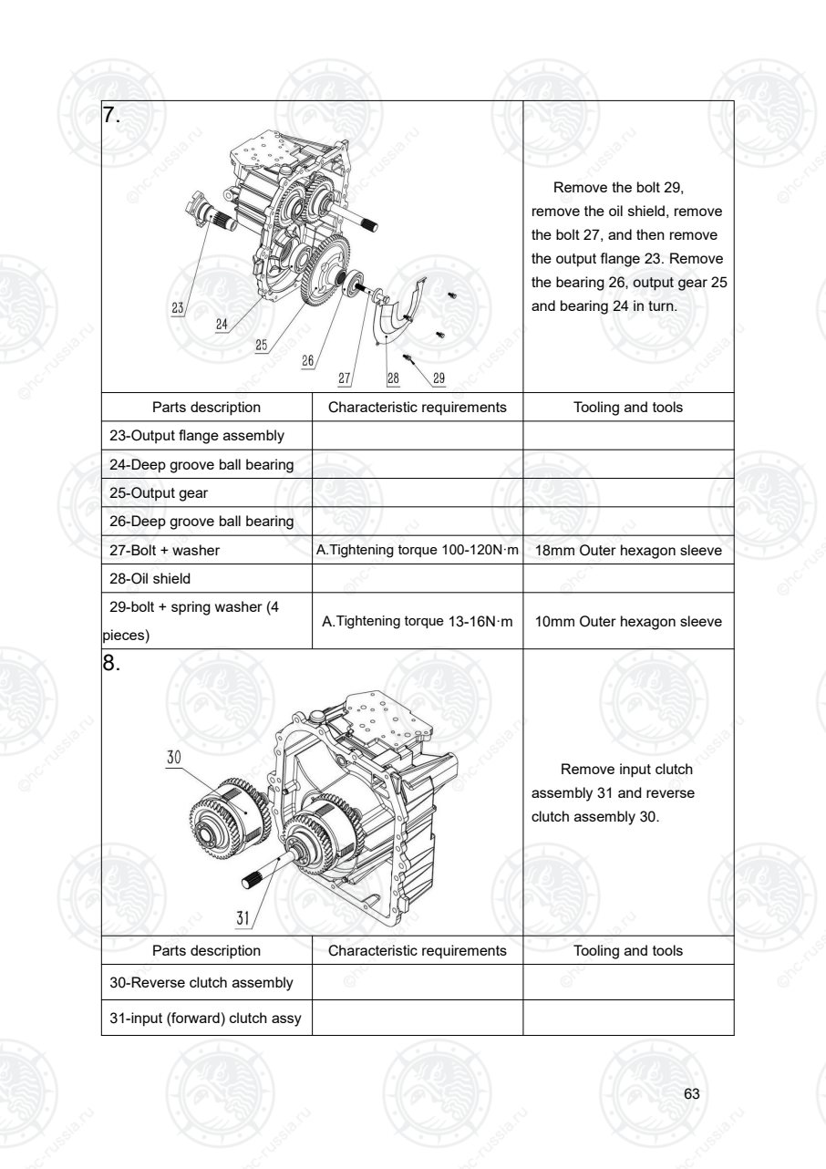
Страница 68
64
9.
Remove the bolt 32 and
spring pad 33, remove the oil
filter seat 34 and paper pad 35,
and remove the primary filter
36. If the paper pad is
damaged during installation,
the paper pad shall be
replaced, and the residual
paper pad on the oil filter seat
and shell surface shall be
cleaned during installation.
Parts description Characteristic requirements Tooling and tools
32-Bolt a、Tightening torque 20-26N·m 13mm outer hexagon socket
33-Elastic pad
34-Oil filter seat
35-Paper pad
a、Vulnerable parts (to be
replaced during disassembly)
36-Primary filter
a、Vulnerable parts (to be
replaced during disassembly)
b、Clean every 500 hours and
replace every 2000 hours
Оригинальная страница: таблицы и схемы
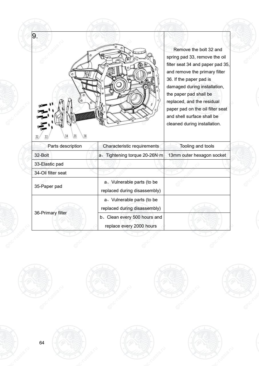
Страница 69
65
10.
 Remove the hexagon
socket bolt 40, the cover plate
41, the paper pad 39, the
springs 38, 42 and the piston
37. If the paper pad is
damaged during installation,
the paper pad shall be
replaced, and the residual
paper pad on the cover plate
and shell surface shall be
cleaned during installation.
Remove the main pressure
valve plug 43, remove the
spring 45 and piston 46, and
replace the O-ring 44 during
installation.
Parts description Characteristic requirements Tooling and tools
37-Piston (2 pieces)
38-Spring of lubricating oil
safety valve
39-Paper pad
a、Vulnerable parts (to be
replaced during disassembly)
40-Socket head screw (4) aTightening torque 9-11N·m 5mm inner hexagon spanner
41-Cover plate
42-Torque converter relief
valve spring
43-Main pressure valve plug a、Tightening torque 65-80N·m 12.7mm Square sleeve
44-O-ring
a、Vulnerable parts (to be
replaced during disassembly)
45-Main pressure valve spring
46-Main pressure valve piston
Оригинальная страница: таблицы и схемы
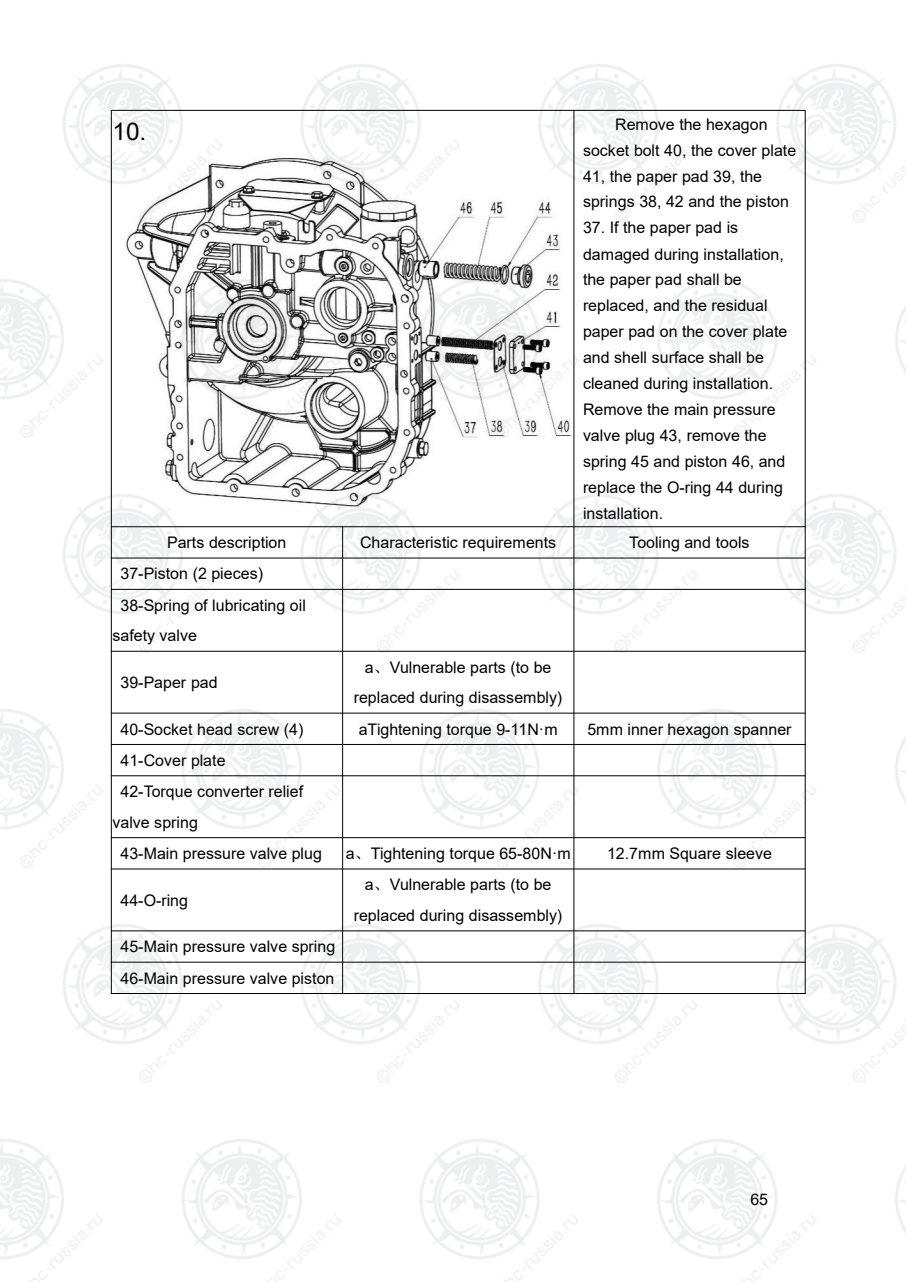
Страница 70
66
11.
Use the filter wrench to
remove the fine filter 48 and
the pipe joint, and remove the
oil dipstick 49 and the air cap
assembly 47.
Parts description Characteristic requirements Tooling and tools
47-Cap assembly
48-
Coupling
Fine filter
a、Vulnerable parts (to be
replaced during disassembly)
Filter wrench
b、Replace every 500 hours
c、Tightening torque 35-40N·m
49-Oil dipstick
Оригинальная страница: таблицы и схемы
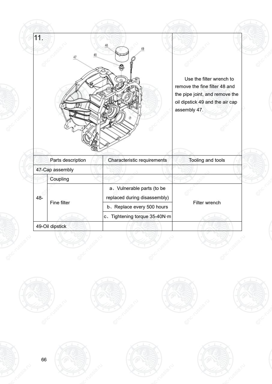
Страница 71
67
12.
Remove the sealing rings
50 and 58, remove the
bearings 51 and 57, remove
the retaining ring 56, and then
remove the bearing 55, clutch
gear 54, hole retaining ring 53
and bearing 52 in turn.
Parts description Characteristic requirements Tooling and tools
50(58)-Seal ring (3 pieces)
a、Vulnerable parts (to be
replaced during disassembly)
51-Bearing
52-Bearing
53-Elastic ring for hole
54-Clutch gear
55-Bearing
56-Circlip for shaft
57-Bearing
13.
After removing the
retaining ring 62, take down
the lower end plate 61, the
inner friction plate 60 and the
outer friction plate.
Parts description Characteristic requirements Tooling and tools
59(63)-outer friction plate (5
pieces)
a、Vulnerable parts (to be
replaced during disassembly)
60-Internal friction plate (5
pieces)
a、Vulnerable parts (to be
replaced during disassembly)
61-End plate The clearance between end plate and
retaining ring should be 1.55-1.75mm
Feeler gauge
62-Elastic ring for hole
Оригинальная страница: таблицы и схемы
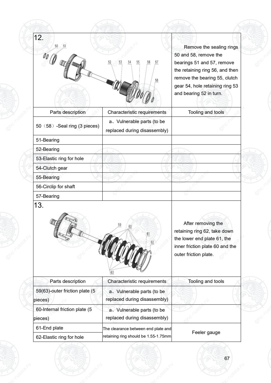
Страница 72
68
14.
Remove the shaft retaining
ring 68, remove the spring seat
67, return spring 66, and
remove the piston 65 and O-ring
64.
Parts description Characteristic requirements Tooling and tools
64-
O-ring a、Vulnerable parts (to be
replaced during disassembly)
O-ring a、Vulnerable parts (to be
replaced during disassembly)
65-Piston
66-Return spring
67-Spring seat
68-Elastic ring for shaft
15.
Remove the seal ring 69,
remove the bearings 70 and
76, remove the retaining ring
75, and then remove the
bearing 74, clutch gear 73,
hole retaining ring 72 and
bearing 71 in turn.
Parts description Characteristic requirements Tooling and tools
69-Sealing ring (2 pieces)
a、Vulnerable parts (to be
replaced during disassembly)
70(76)-Bearing (2 pieces)
71-Bearing
72-Circlip for shaft
73-Clutch gear
74-Bearing
75-Circlip for shaft
Оригинальная страница: таблицы и схемы
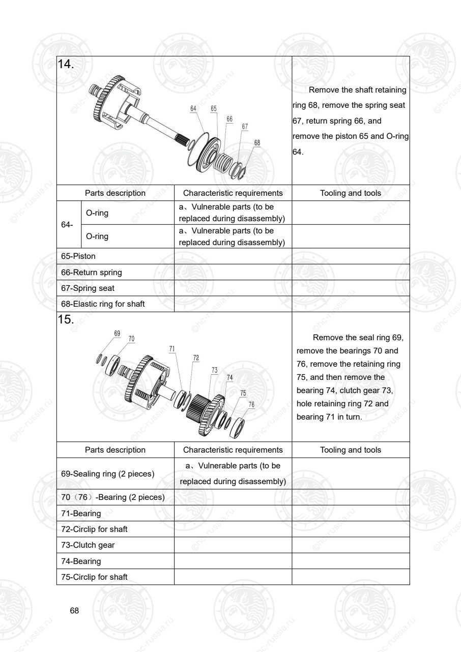
Страница 73
69
16.
After removing the
retaining ring 79, remove the
lower end plate 78, the inner
friction plate 80 and the outer
friction plate 77 in turn
Parts description Characteristic requirements Tooling and tools
77-external friction plate (5
pieces)
a、Vulnerable parts (to be
replaced during disassembly)
78-end plate The clearance between end
plate and retaining ring should
be 1.55-1.75mm
Feeler gauge
79-Elastic ring for hole
80-Internal friction plate (5
pieces)
a、Vulnerable parts (to be
replaced during disassembly)
17.
Remove the shaft retaining
ring 86, remove the spring seat
65, return spring 84, and
remove the piston 83 and
O-rings 82 and 81.
Parts description Characteristic requirements Tooling and tools
81-O-ring a、Vulnerable parts (to be
replaced during disassembly)
82-O-ring a、Vulnerable parts (to be
replaced during disassembly)
83-Piston
84-Return spring
85-Spring seat
86-Elastic ring for shaft
Оригинальная страница: таблицы и схемы
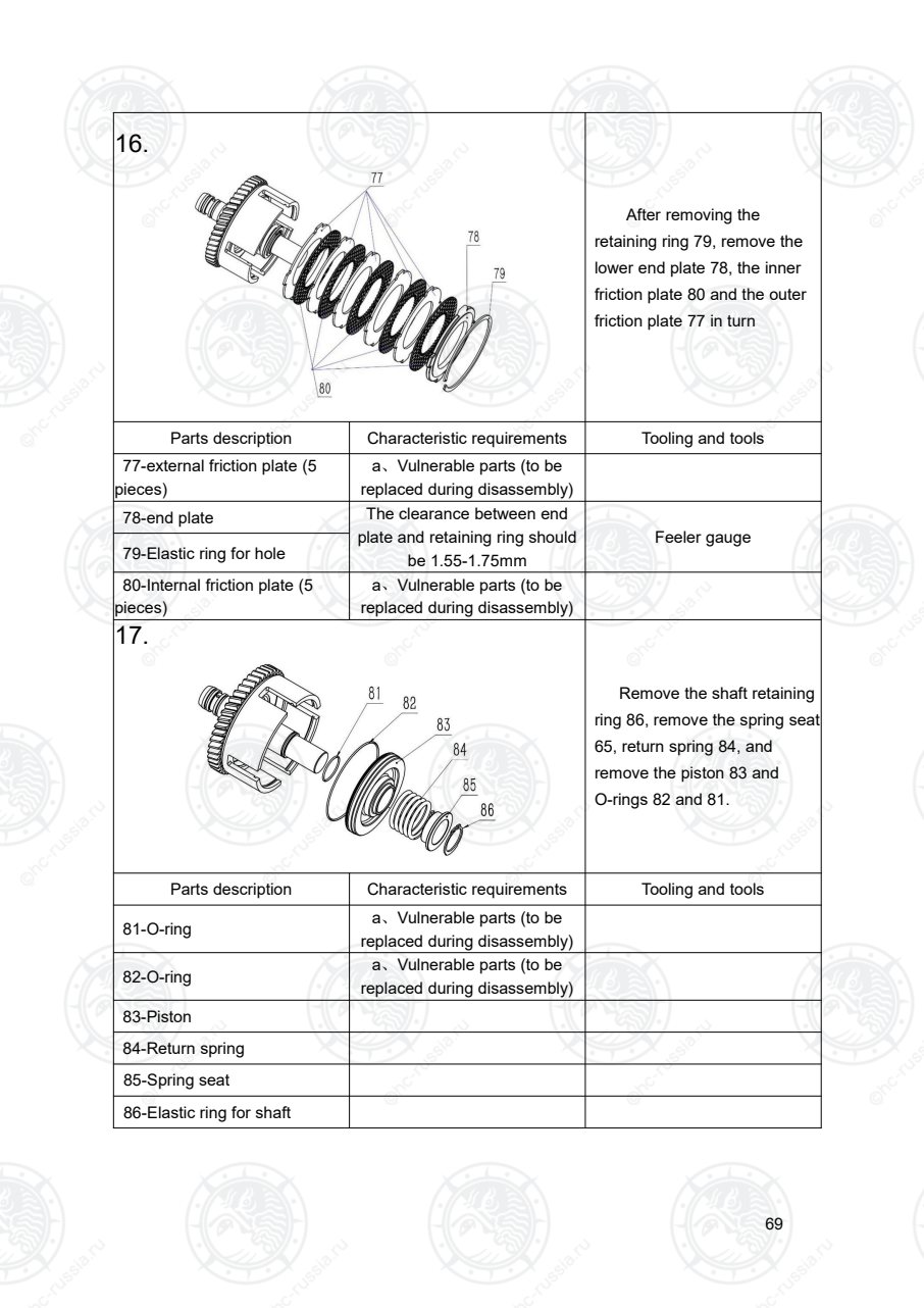
Страница 74
70
18.
After removing the screw
87, remove the pump body
assembly 91, oil pump driving
gear assembly 90, oil pump
inner ring gear 89 and oil seal
92.
Parts description Characteristic requirements Tooling and tools
87-Screw
a、The end face of the screw
after installation shall not be
higher than the end face of the
guide wheel seat
Cross screwdriver
88-Guide wheel seat
89-Oil pump inner gear ring After installation, the end face of
the oil pump gear is
0.04-0.055mm lower than the
end face of the pump body
Lever dial indicator90-Oil pump driving gear assy
91-Pump body assembly
92-Oil seal
a、Vulnerable parts (to be
replaced during disassembly)
Оригинальная страница: таблицы и схемы
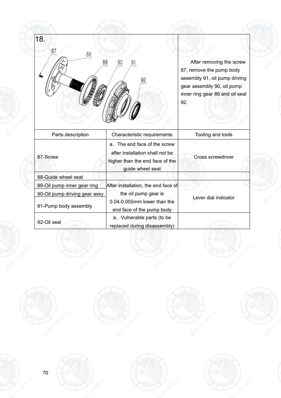
Страница 75
71
19.
Remove the split pin 97,
remove the bolt 96, and then
remove the bearing seat 95.
When removing and installing,
pay attention to that the left
and right bearing seats are not
interchangeable. Remove
adjusting nut 93 and
differential assembly 94.
Parts description Characteristic requirements Tooling and tools
93-Adjusting nut
a、After the adjustment nut is
installed, the clearance of spiral
bevel gear shall be controlled
within 0.26-0.34mm
Lever dial indicator
a、After the adjustment nut is
installed, the rotation torque at
the input flange 113 should be
controlled at 5-6 N · M
Torque wrench with Watch
94-Differential assembl
95-Bearing block (2 pieces)
a、Left and right are not
interchangeable
96-Bolt (4 pieces)
a、Tightening torque
325-380N·m
27mm Outer hexagon socket
97-Split pin (2 pieces)
Оригинальная страница: таблицы и схемы
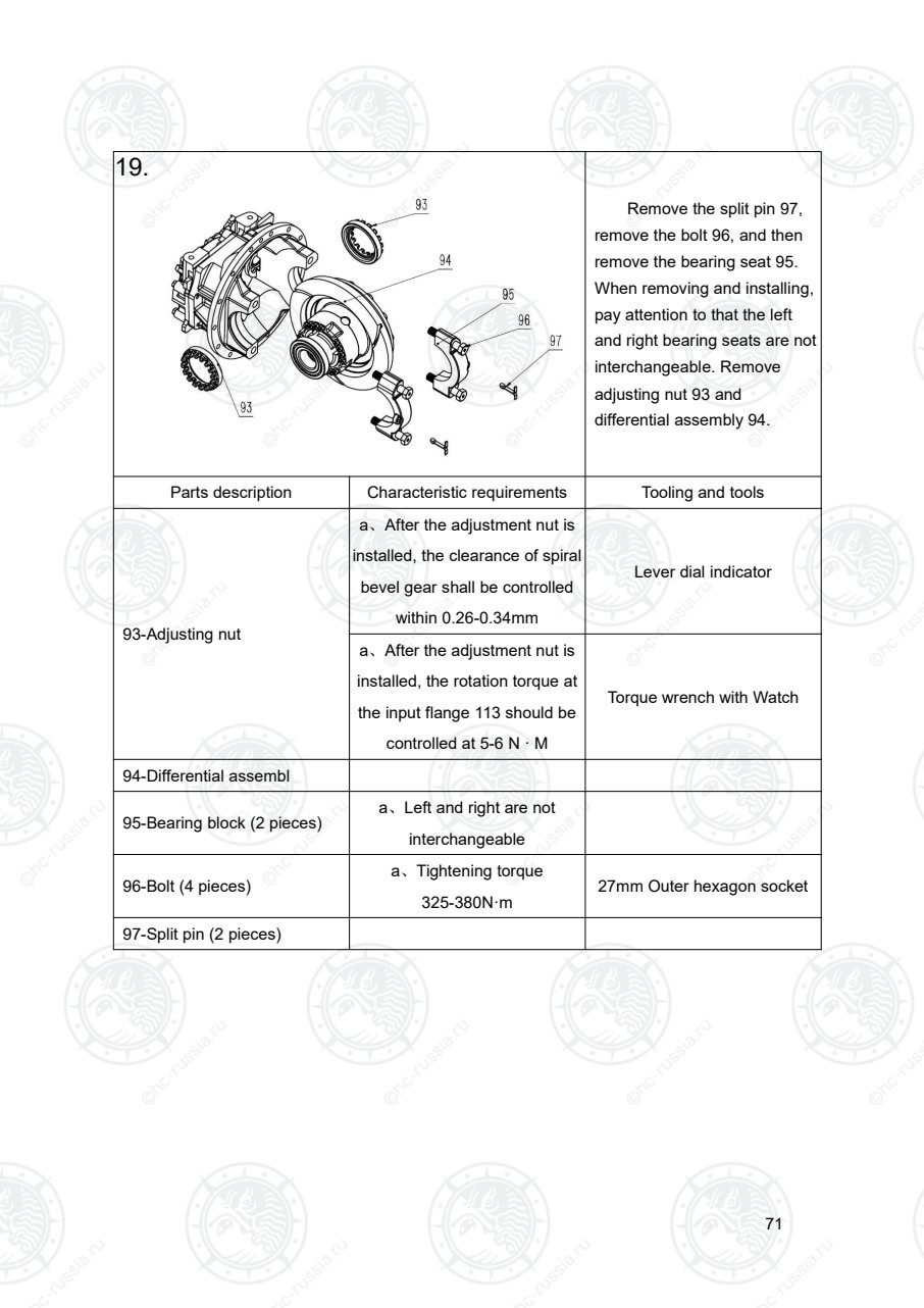
Страница 76
72
20.
Remove the bolt 109,
remove the end cover of driven
shaft, and apply plane sealant
on the joint surface during
installation; chisel the notch on
the lock nut 107, remove the
lock nut, remove the adjusting
pad 106 and bearing 105;
remove the input flange 113,
remove the bolt 111, and
remove the differential cover
110, and apply plane sealant
on the joint surface during
installation. Remove the
driving gear assembly 103, the
driven gear 104, and the
cylindrical pin 102. Remove
the conical roller bearing 100,
bevel gear bearing 99.
Parts description Characteristic requirements Tooling and tools
98-Driving spiral bevel gear
99-Bearing
100-Adjustment pad
After the adjustment pad is installed, the
tooth surface contact area of the driving
spiral bevel gear should be in the middle
of the gear, and the area should be ≥ 60%
Inspection of Huangdan powder
101-Differential seat assembly
102-Cylindrical pin(2)
103-Driving gear assembly
104-Driven gear
105-Bearing
106-Adjustment pad
a、After the adjustment pad is
installed, the rotation torque at
the input flange 113 should be
controlled at 4-5 N · m
Torque wrench with Watch
107-Lock nut
Tightening torque 323-363N·m 55mm outer hexagon socket
b、After tightening, use a chisel to flatten
and lock the notch on the shaft
108-Driven shaft end cover
109-Bolt+ pad (5) a、Tightening torque 27-34N·m 13mm hexagon socket
110-Differential cover
111-Bolt+ pad (10) a、Tightening torque 60-75N·m 16mm hexagon socket
112-oil seal a、Vulnerable parts (to be
replaced during disassembly)
113-Flange as-input
Оригинальная страница: таблицы и схемы
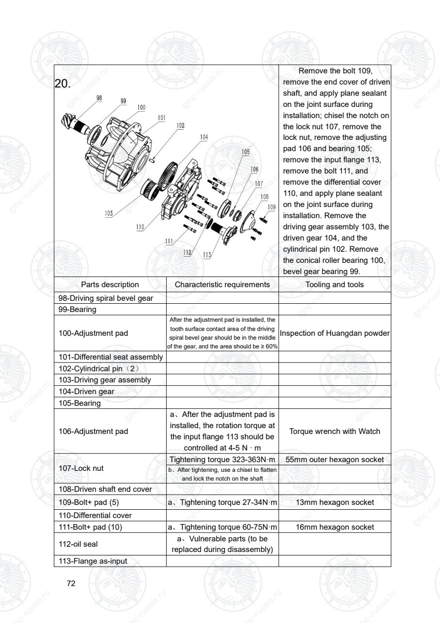
Страница 77
73
21.
Remove the bolt 114, the
driven spiral bevel gear 117
and the tapered roller bearing
115 at both ends.
Parts description Characteristic requirements Tooling and tools
114-Bolt (12 pieces) Tightening torque 180-210N·m 22mm outer hexagon sleeve
115-Bearing (2 pieces)
116-Differential assembly
117-Driven spiral bevel gear
Оригинальная страница: таблицы и схемы
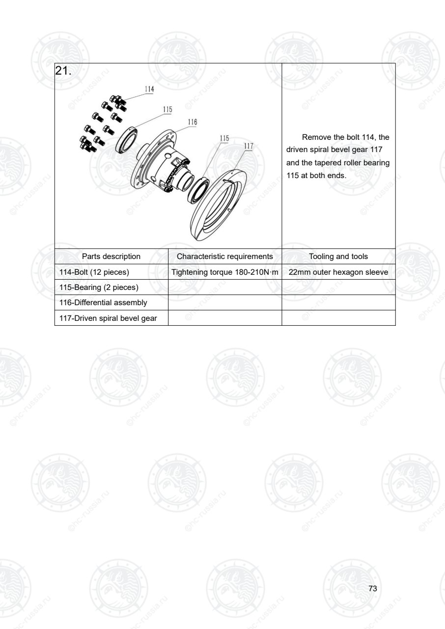
Страница 78
74
22.
Remove the bolts 124,
open the left and right half
housings 118 and 123 of the
differential, and take out the
internal thrust washer 119, half
shaft gear 120, planetary gear
122, washer 121 and cross
shaft 125.
Parts description Characteristic requirements Tooling and tools
118-Differential left half
housing
The replacement should be
matched with Part 123
119-Washer (2 pieces) The clearance between the two
parts after installation is
required to be 0.3-0.45mm120-Half shaft gear (2 pieces)
121-Washer (4 pieces)
122-Planetary gear (4 pieces)
123-Differential right half
housing
The replacement should be
matched with part 118
124-Bolt (16 pieces) Tightening torque 75-100N·m 14mm outer hexagon sleeve
125-Cross shaft
Оригинальная страница: таблицы и схемы
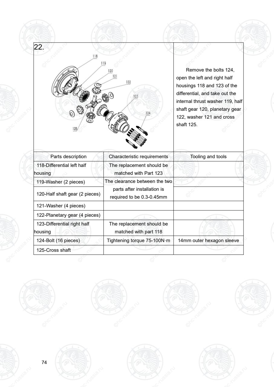
Страница 79
75
23.
Remove the bolts 128 and
remove the elastic plate
assembly 127.
Parts description Characteristic requirements Tooling and tools
126-Torque converter assy
127-Washer
128-Bolt (8 pieces) a、Tightening torque 50-59N·m 13mm external hexagon wrench
2、Matters needing attention
2.1、The sequence of disassembly and assembly of transmission is basically opposite.
2.2、When disassembling and assembling the gearbox, it should be handled with care to
prevent the parts from being damaged. After disassembling, the parts should be placed in
order. The parts to be reassembled should be cleaned with kerosene and dried with dry
high-pressure air before assembly.
2.3、The adjusting gaskets in the gearbox shall be installed back to the original place
according to the quantity during disassembly, and shall not be increased, decreased or
replaced at will.
2.4、The disassembly process should be operated in strict accordance with the above
instructions. Blind disassembly and barbaric operation are strictly prohibited.
Оригинальная страница: таблицы и схемы
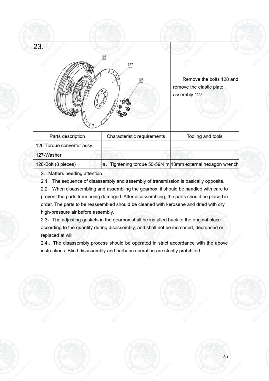
Страница 80
76
Ⅵ. Driving axle
1. Date
Driving axle type Full floating, axle and truck body direct
install, front wheel driving
Tire pressure
790kPa 1.0t-1.8t
860kPa 2.0t-2.5t
830kPa 3.0t-3.8t
Wheel hub rotation starting
torque at hub blot N 10~29
Axial play of wheel bearing mm < 0.08
2. Trouble diagnoses and corrections
condition Probable cause Corrective action
Abnormal noises
·loose driving axle and body connecting
blots.
·loose wheel nut
·worn or damaged wheel hub bearing.
·wheel hub bearing not properly adjusted.
·worn axle shaft spliner.
·insufficient lubrication
Tighten.
Tighten.
Replace.
Adjust.
Replace.
Lubricate.
Unstable driving
·loose wheel nut.
·deformed wheel.
·worn or damaged wheel hub bearing.
·loose driving axle and body connecting
blots.
·wheel hub bearing not properly adjusted.
·improper tire pressure.
Tighten.
Replace.
Replace.
Tighten.
Adjust.
Adjust.
Oil leakage
·worn or damaged axle shaft oil seal.
·final drive improperly installed.
·loose drain plug.
Replace
Replace gasket.
Tighten.
Оригинальная страница: таблицы и схемы
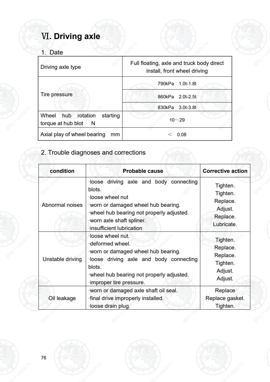
Страница 81
77
1.0-1.8t Drive axle
1.Plug 2.Vented plug 3.Plug 4.Washer 22 5.Washer 20 6.Plug
7.Axle 8.Washer 10 9.Bolt 10.Washer 12 11.Bolt 12.Plate
13.Plate 14.Plate 15.Washer 18 16.Nut 17.Left brake 18.Right brake
19.Bolt 20.Nut M12×1.5 21.Brake drum 22.Oil seal 23.Bearing 24.Hub
25.Lock nut 26.Locking shim 27.Washer 6 28.Bolt M6×12 29.Oil seal 30.Gasket
31.Half shaft 32.Clamp split-ring 33.Bolt 34.Pin 10×30 35.Snap block 36.Snap block
37.Plug 38.Washer 16 39.Nut M16×1.5 40.Washer 16 41.Bolt 42.Nut
43.Bearing3312 44.O-ring 75×3.1
Tighten torque:N.m
1.5t-1.8t Remark
Support plate fixed nut(part 11) 260-347
Conical surface on
wheel hub nut needn't
lubricate grease
Brake drum fixed nut(part 16) 260-347
Bolt, Brake plate assy(part 19) 106-158
Wheel hub nut(part 39) 157-176
Half shaft bolt(part 33) 65-78
Оригинальная страница: таблицы и схемы
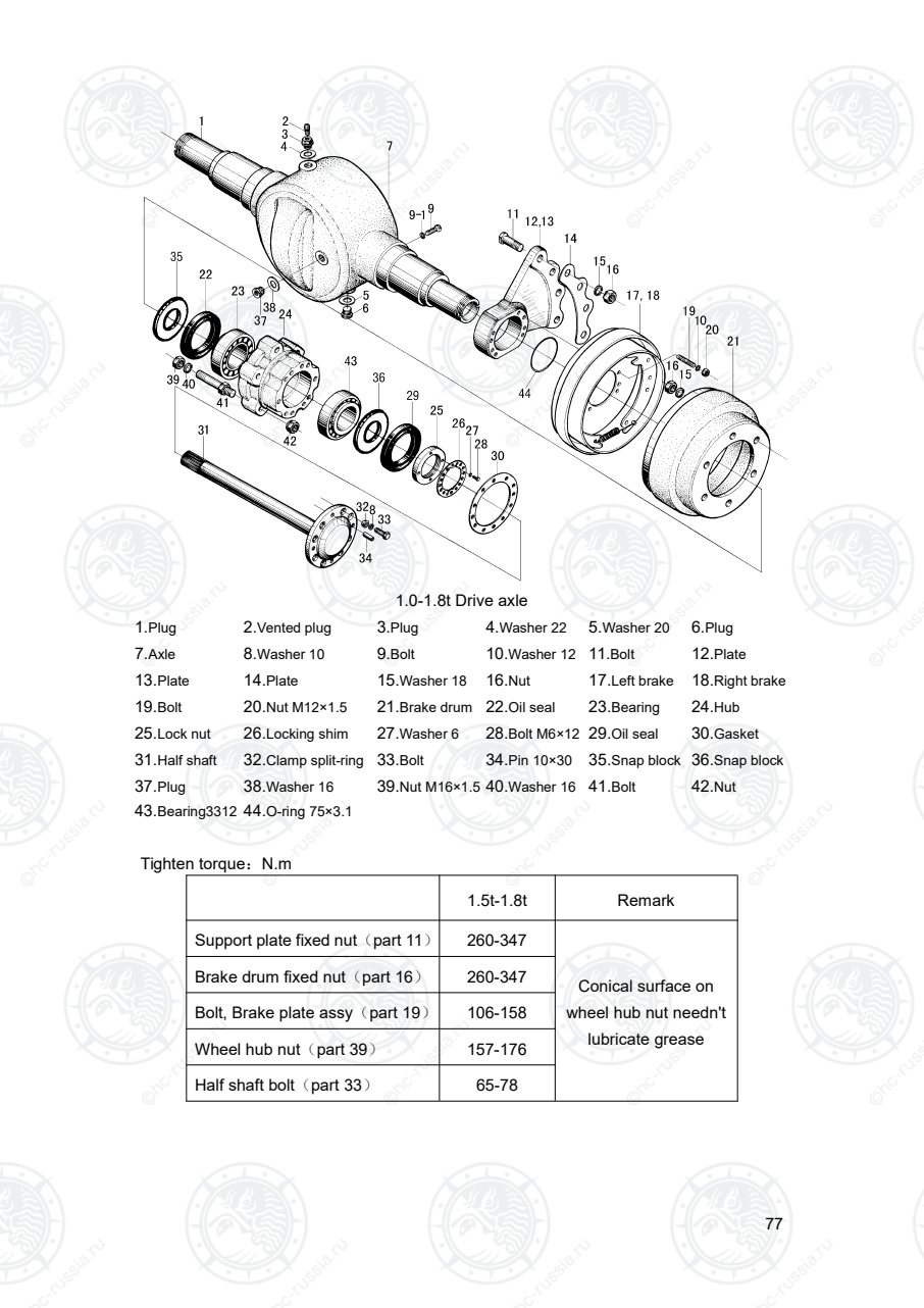
Страница 82
78
2.0-3.8t Drive axle
1. Left brake 2. Left Plate 3. Plug M16×1.5 4. Washer 16 5. Vented plug 6. Plug
7.Washer 22 8. Plug 9. Washer 20 10. Axle 11. Bolt 12. Right Plate
13. Plate 14.Washer 20 15.Nut M20×1.5 16.Right brake 17.Washer 14 18.Bolt
19.Oil seal 20.Oil Seat 21.Bearing7816 22.Brake drum 23.Hub 24.Bolt, Hub
25.Nut, Hub 26.Bearing781
5
27.Lock nut 28.Locking shim 29.Washer 6 30.Bolt M6×12
31.Oil seal 32.Gasket 33.Half shaft 34.Pin D12×35 35.Clamp split-ring 36.Washer 12
37.Bolt 38.Hub
Tighten torque:N.m
2.0t-3.8t Remark
Support plate fixed nut(part 11) 324-373
Conical surface on
wheel hub nut needn't
lubricate grease
Brake drum fixed nut(part 15) 324-373
Bolt, Brake plate assy(part 18) 90-210
Wheel hub nut(part 25) 363-490
Half shaft bolt(part 37) 90-110
Оригинальная страница: таблицы и схемы
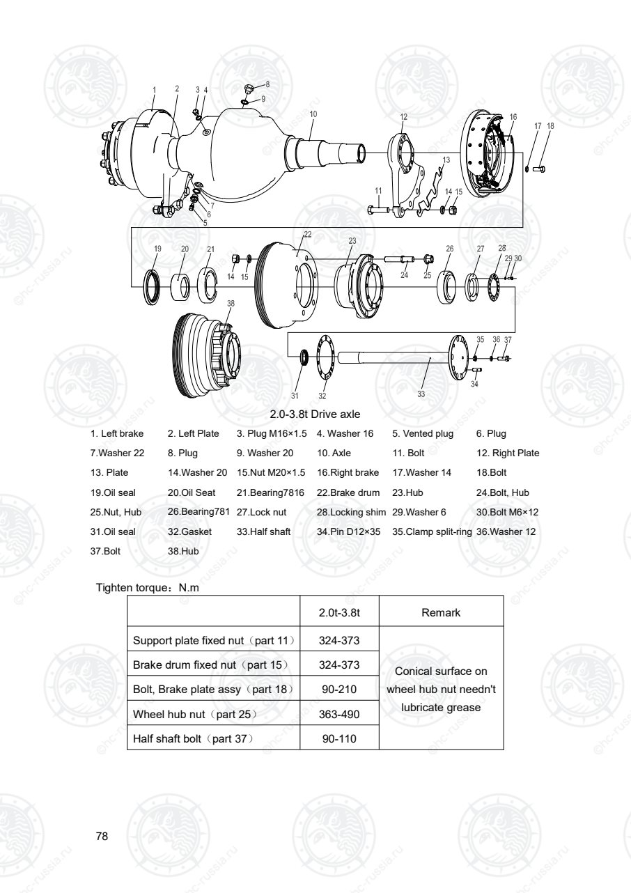
Страница 83
79
3. Assembly and disassembly of driving axle
WARNING
Be careful when removal and installation driving axle as it is heavy.
Raise front end of forklift truck and support frame with wooden blocks.
1) Remove mast assembles.
2) Slightly raise axle with a hoist and place wooden blacks under differential
gear carrier and transmission case.
3) After placing a pan under axle case, loose oil plug, drain oil from axle
case.
4) Disconnect brake nuts from left and right cylinders.(see fig.5-1)。
CAUTION:plug brake tube openings to prevent oil from flowing out.
5) Disconnect brake cable at hand brake lever.
6) Remove front wheels.
7) Remove axle shaft.
8) Support driving axle with wire ropes and lifting device.
9) Remove bolts securing axle mounting bracket to frame.(see fig.5-2).
10) Remove nuts securing axle case to differential gear carrier.(see fig.5-3).
11) Remove driving axle assemble.
Fig.5-1 Fig.5-2 Fig.5-3
13)Remove brake drum,remove wheel hub.
14) Remove axle mounting bracket and brake component from axle tube.
15) Remove oil seal from axle tube.
16) To install driving axle assemble in the reverse order of removal. Observe
the following:
1 When installing axle mounting bracket and brake component, apply a coat
of calcium grease to axle tube.
2 Apply 1/3~2/3 of volume of calcium grease to wheel hub,then install them
on axle tube.
3 Install oil seal with its part number facing to the inside of forklift truck.
4 Attach seal tape (PVC, white)to drain plug then installed after cleaned it.
5 Replenish axle case with gear oil. Tighten vent plug after clearing.
Оригинальная страница: таблицы и схемы
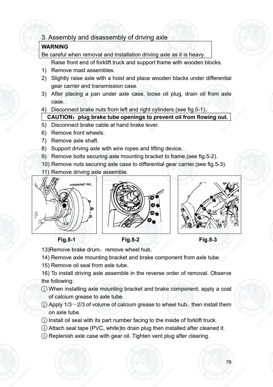
Страница 84
80
TonModels
Fill in drive axle(L)
1.0t-1.8t 2.0t-2.5t 3.0t-3.5t Remark
Gear Oil: GL-5 85W/90
4.5L 5.4L 10.3L Mechanical forklift truck
2.6L 2.7L 6.5L
Hydraulic Transmission
Forklift truck
Vent plug should clear instantly to prevent pressure inside of wheel hub from
rising.
4. Axle shaft and wheel hub
Remove
1) Raise the front end of forklift truck and support frame with wooden blocks.
2) Remove front wheel and axle shaft.
3) Remove lock nuts, lock washers, snap ring, felt ring, adjusting nut. Use
special tools.
4) Remove brake drum(refer to Fig.5-4);
If brake drum is difficult to remove: a. Remove adjusting hole plug. Then
with flat-blade screwdriver extend adjusting hole, turn adjusting ratchet
wheel by 10 notches. To contract brake shoe lining(refer to Fig.5-5). b.
evenly tapping on brake drum with brass bar or wooden mallet.
Fig.5-4 Fig.5-5
5) Remove wheel hub, be careful not to drop bearing inner race.
6) Remove oil seal and inner bearing as an assembly by evenly tapping on
periphery of seal with a wooden mallet and brass bar.
7) Remove bearing outer race from wheel hub by evenly tapping on its
periphery with a wooden mallet.
CAUTION:Be careful not to damage oil seal and outer race.
Оригинальная страница: таблицы и схемы
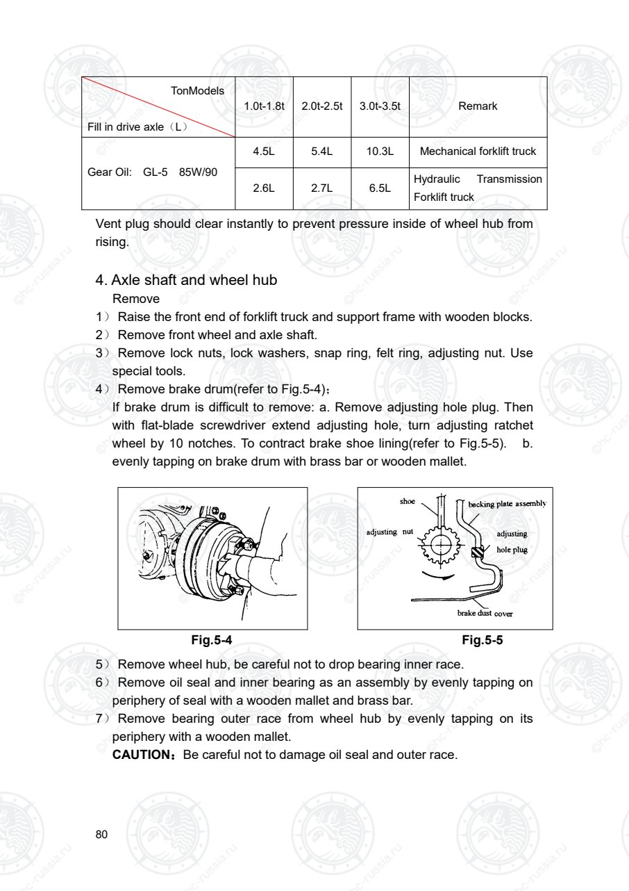
Страница 85
81
Inspection
Stepped wear or cracks on axle shaft splines replace
Seized, scratched, noisy or rusted bearing or improper
rotation of rollers Replace
Cracked or damage wheel hub Replace
Damaged oil seal felt ring. replace
Installation
Install reverse order of removal.
5. Bearing adjusting
1) Lubricate on taper roller bearing.
2) Tighten roller bearing lock nut in wheel hub until wheel hub can no longer
be rotated with one hand.
3) From that position, turn back lock nut approx. 600.
4) Turn back wheel hub two or three rotations so that bearing settles down.
5) Again tighten lock nut until it can no longer be rotated with one hand; then
turn back approx.600.
6) Install snap ring and settles down felt ring, install lock washer so as to set
its hole in the pin of snap ring. Screw lock nut.
7) Turn wheel hub back and forth two or three rotations to see if rotation
starting torque is within specifications. Rotation starting force:10N~29N
(refer to Fig.5-6);
8) Measure axial play of wheel hub to see if it is within specification. Axial
play is less than 0.10mm (refer to Fig.5-7).
Fig.5-6 Fig.5-7
Оригинальная страница: таблицы и схемы
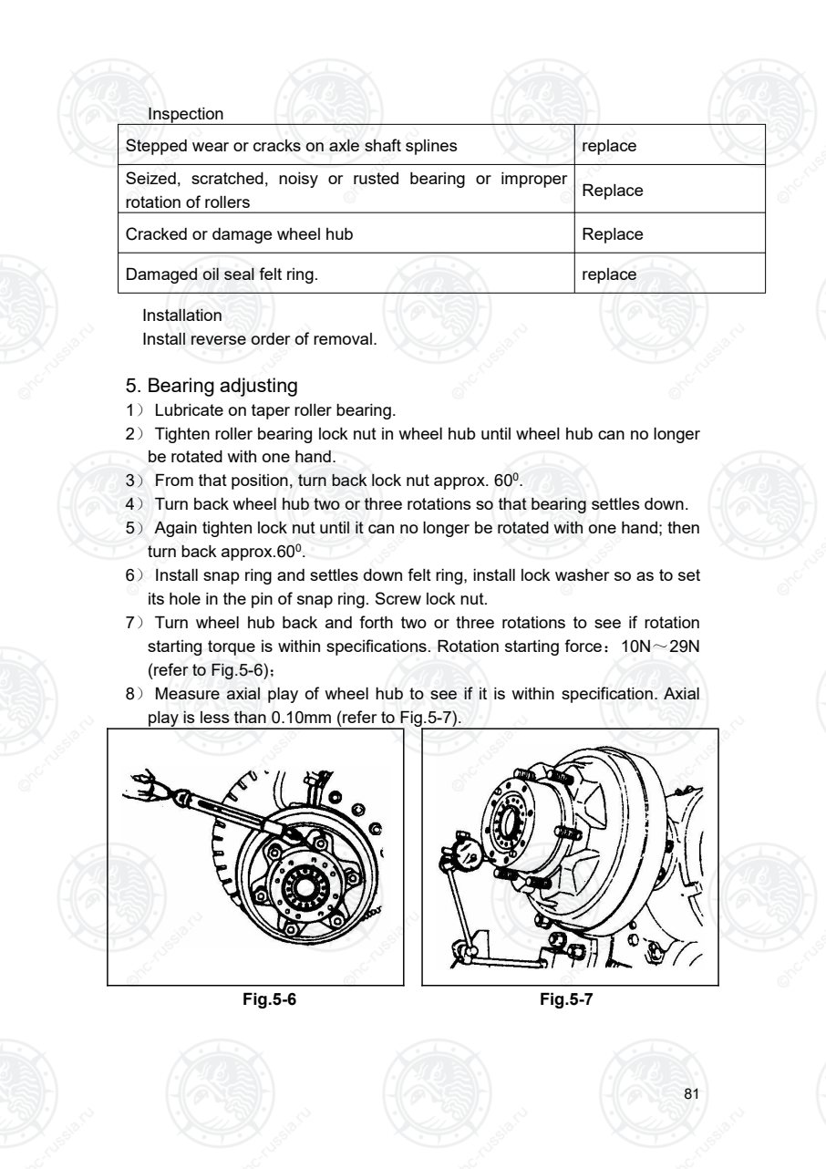
Страница 86
82
Ⅶ. Steering axle
1. General specifications
Axle
body
type
Center-pivoted, turn
around type
Axle centre
Vertical play(mm) 0~0.5
Turning
angle
Inside
turning
angle
1-1.8t 81.5° Adjusting shim
for end shaft of
axle
0.5,1.0,1.6
2-3.8t 77.2°
Outside
turning
angle
1-1.8t 57.5°
wheel hub bearing
2-3.8t 56°
Pre-tighten
Tighten steering spindle
nut until drive wheel hub
no longer rotates with one
hand. Then loose 1/8~
1/6 rotations.
Or wheel hub bolt force
is10~29.8N
Tyre
pressure
1000kPa 1.0t-1.8t
860kPa 2.0t-2.5t
790kPa 3.0t-3.8t
Axial
play(mm) Less than 0.10
2. Trouble diagnoses corrections
condition Probable cause Corrective action
Unstable
driving
·loose wheel nut
·wheel bearing out of adjustment
·improperly adjusted shims.
·faulty steering system.
tighten
adjust
adjust
refer to turning system
section
Noises
·insufficient lubrication
·loose bolts and nut
·improperly adjusting shim for axle
end Shaft.
·damaged joint bearing at two ends of
rod.
Apply calcium grease
tighten
adjust
replace
Оригинальная страница: таблицы и схемы
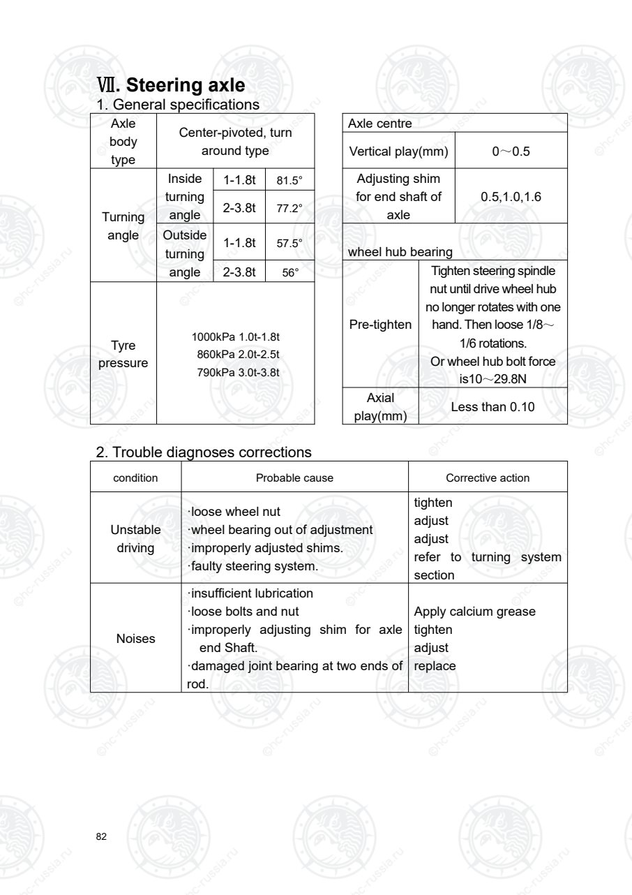
Страница 87
83
3. Structure
28
31
30
29
5
6
14、45
13
12
11
10
98
7
5
6
4
3
1
15
16
17
18
20
19
23 22
21
41
24
43
37
2442
44
19 40
39
38
36
36
35
34
33
32
27
29
28
30
31
5
4
25
26
15
2
46
47
1.0t-1.8t Steering axle
1.Nut 2.Bolt 3.Bolt 4.End cover 5.Bolt M6×12 6.Washer 6
7.Washer 8.Lock nut 9.Bearing30305 10.Steering hub 11.Bearing30208 12.Oil seal
13.Adjust shim 14.Left steering knuckle 15Washer 10 16.Screw 17.Nut 18.Bolt
19.Grease
nipple
20.Bearing 21.Grease
nipple
22.Washer 16 23.Bolt 24.Bush
25.Pin 26.Bush Ⅰ 27.Rubber seal
ring
28.Bearing 29.Oil seal Ⅱ 30.Gasket
31.End cover 32.Bush Ⅰ 33.Pin 3.2×40 34.Nut M14×1.5 35.Tie-rod bar 36.Washer
37.Bush Ⅱ 38.Tie-rod bar 39.Pin shaft 40.Grease
nipple
41.Grease nipple 42.Steering
axle body,
Welding
43.Adjust shim 44.Steering cylinder 45.Right steering
knuckle
46.Gasket 47.Damper
Оригинальная страница: таблицы и схемы
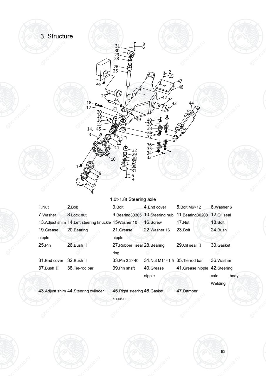
Страница 88
84
2.0t-3.5t Steering axle
1.Bolt 2.Washer 10 3. Damper 4.Bolt 5.Washer 18 6.axle body
7.Grease nipple 8. Pin shaft 9.Bolt M6×12 10.Washer 6 11.Dustproof ring 12.Snap
ring-B35
13.Bearing 14.Oil seal 15.BushⅡ 16.Steering cylinder 17.Grease
nipple
18.Bush
19.Adjust shim
2.0t-3.5t Steering axle
1.End cover 2.Bolt M6×12 3. Washer 6 4.Washer 5.Lock nut 6.Bearing322083DC
7Nut 8. Steering hub 9.Bolt 10.Bearing32103D
C
11.Oil seal 12. steering knuckle
13.Lock nut 14.O-ring 15.dust boot 16..Bearing 17.Washer 18.O-ring
19.Spacer 20.Pin
Оригинальная страница: таблицы и схемы
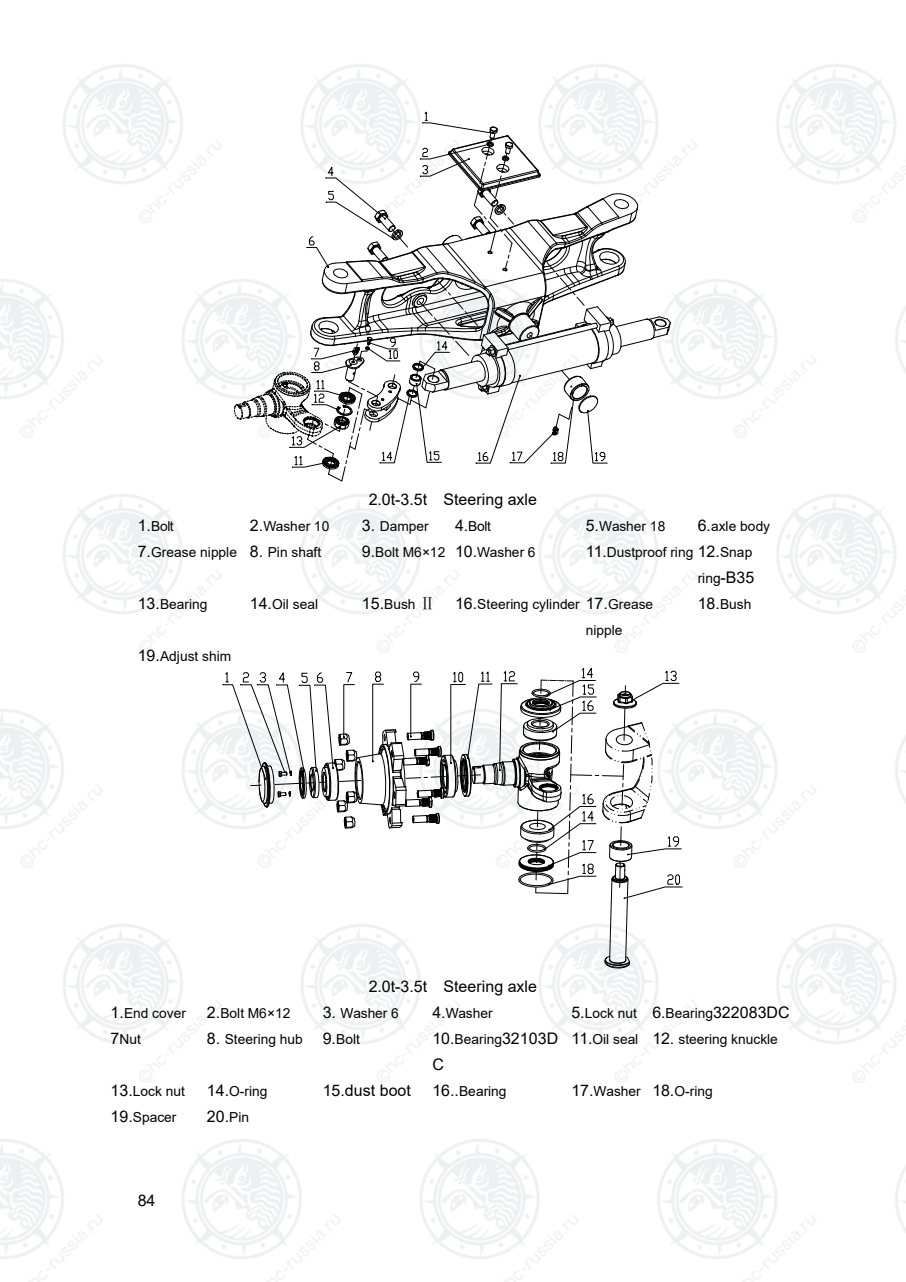
Страница 89
85
4.Steering axle Assembly and disassembly
Remove wheel hub
1) Jack up and support forklift truck body with wooden blocks.
2) Remove tire.
3) Remove hubcap.
4) Remove steering spindle nut.
5) Pull off hub assembles.
6) Remove bearing inner race.。
caution:a. Not to drop bearing inner race. b. Be careful not to damage
oil seal.
5.Kingpin and steering spindle.
1) Remove rod.
2) Loose lock bolts.(see fig.6-2);
3) Remove grease nipples on kingpin.
4) Remove kingpin.
caution:Hold kingpin to prevent it from dropping. (See fig.6-3).
5) Take off spindle, thrust bearing and shim.
Fig. 6-2 Fig. 6-3
INSPECTION:
1).Replace spindle if cracked.
2).Replace bearing if its rollers or roller surfaces are rusted or nicked.
3).Replace steel sleeve if it distortion, out of round, cracked.
4).Replace thrust bearing and dust cap if them damaged.。
Installation
To install, reverse the order of removal. Careful observes the following.
1) Always insert kingpin from lower side.
2) Install thrust bearing, set the tighten-ring below the support and loosen-ring.
Pack all grease between dust proof inside, loosen-ring, and tighten-ring.
3) Adjust axial play to specification with shims. Axial plays less than 0.15mm.
4) The character of seal tape faces outside. Apple grease to roller of roller
bearing, also apply grease between lip and groove of seal tape.
5) Pack all grease nipples with a sufficient of grease.
Оригинальная страница: таблицы и схемы
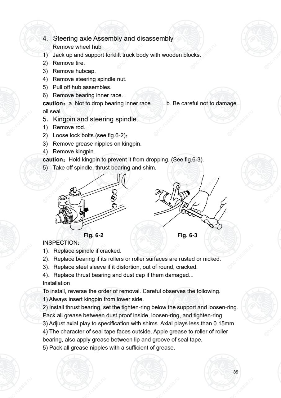
Страница 90
86
6.Wheel bearing adjustment
1) Slowly rotate hub. Tighten steering spindle nut until it can no longer be
rotated with one hand.
2)From that position, turn back steering spindle nut 1/6~1/4 rotation. Measure
hub bolt force is 10N~30N.
3) Make sure that hub rotates smoothly and that its axial play is within
specification. Axial play is less than 0.10mm.
7.Steering cylinder
Fig. 6-4
1.Piston rod
2.LBH dust
ring
3. Protect ring 4.ISI gasket ring
5. Compound
bushing
6. Guide sleeve 7.O-ring 8.Steel cylinder 9.Glyd ring 10.Screw 11.Nut
Disassemble:
1)Loose nut 10, remove bolt 11;
2)Remove guide sleeve 6 at left and right side;
3)Remove LBH dust ring 2, protect ring 3, LSI gasket ring, compound bushing 5, O-ring 8
in turn;
4) Remove piston rod, remove glyd ring 9;
5) Inspecting: if any component is damaged, please replace.
Оригинальная страница: таблицы и схемы
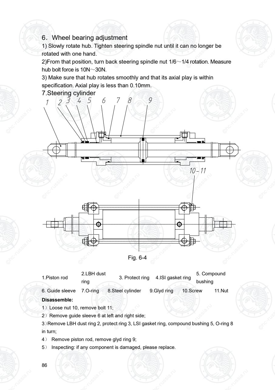
Страница 91
87
To install, reverse the order of removal.
Careful observes the following:
6) Lubricate every component with clean hydraulic oil.
7) Prevent dust , oil dirty entering cylinder.
8) Prevent causing woolly grain at cylinder port , inlet and outlet.
9) ISI seal lip direct to inside, LBH dust proof port direct to outside.
10)Pay attention to avoiding scratch O-ring at outside circle when installing.
11)Carefully center, push guide sleeve into cylinder, pay attention to avoid scratch
O-ring at outside and inside circle when installing.
12)Please wipe the same trademark hydraulic oil to lubricate between gasket ring.
Оригинальная страница: таблицы и схемы
Страница 92
88
Ⅷ. Steering system
1. Data
Steering system type Change direction rear wheel with power
steering
2t、2.5t、3t、3.5t、3.8t 1.0t、1.5t、1.8t
cycloidal rotor
full hydrostatic
power steering
gear
Model 532-1323 532-1322
Displacement ml/r 123 100
Type of connection Inner spline Inner spline
Features Open center ,low
torque
Open center ,low
torque
Steerin
g
cylinder
Cylinder diameter mm Φ80 Φ70
Piston diameter mm Φ50 Φ40
stroke mm 188 166
Wheel diameter mm Φ360 Φ300
2.Trouble diagnoses
condition Probable cause Corrective action
Failure to rotate
steering wheel
Damaged or trouble of oil pump replace
Divide value is clogged or damaged. Clean or replace
Damaged hose or connector, block lines Replace or clean
High effort for
steering
Divide value pressure too low. Adjust pressure.
Air in oil lines. Remove air
The steering fails to turn to its natural
position, broken lock spring or insufficient
spring pressure
Replace spring flat
Too much internal leakage in steering
cylinder.
Check piston for
sealing
Track travel
zigzag or
wobbly
Too much oil flow to steering cylinder. Adjust divide value.
normal noise
Oil is not sufficient in oil tank. Add oil.
Suction piping or filter clogged. Clean or replace
leakage Damaged sealing of oriented bush of
steering cylinder or hose or connector. replace
Оригинальная страница: таблицы и схемы
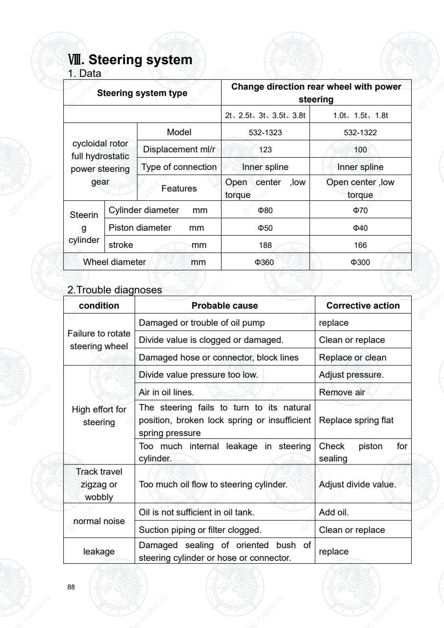
Страница 93
89
3. Summarize
Steering system is composed of full hydrostatic power steering gear and
steering cylinder.
3.1 Full hydrostatic power steering gear assemble(refer to Fig.8-1)
Full hydrostatic power steering gear assemble include cyclical full
hydrostatic power steering gear, column and steering wheel. Column and
steering wheel can be adjust 6°back or forth to fit all driver.
When engine stops running, rotate steering wheel with 1kg force slightly,
after leaving hands, steering wheel should be return 10° auto backing
boardically.
6
16
14151213
15141312
9
87
5
4
3
2
1
10
11
.
Fig. 7-1 steering wheel
1.Steeringwheelassy2.Nut 3.Washer 16 4.Steering pipe device 5.Lock Handle 6.Snap ring
7.Lock shaft 8Lock sleeve Ⅰ 9.Lock sleeve Ⅱ 10.Bolt M10×20 11.Washer 1012.Washer 12
13.Washer 12 14.Bolt 15.Spacer 16.Orbitrol
Оригинальная страница: таблицы и схемы
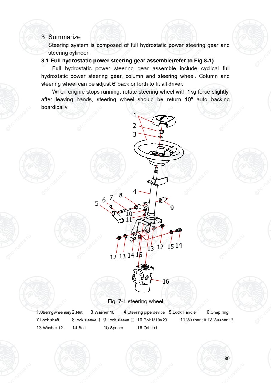
Страница 94
90
3.2 Full hydrostatic power steering gear
3.2.1 cycloidal rotor full hydrostatic power steering gear (refer to
Fig.7-2-1)
When power steering ,pressure oil flows from valve disk and valve
sleeve pair to rotary-stator valve pair , then drive rotary to rotate followed as
steering wheel, and drive oil entering into left or right cavity of cylinder, and
drive steering tire to turn by piston rod .
When the engine stops running, the pump does not supply oil, and the
steering action will be realized manually by turning the steering wheel to move
valve spool, valve guide, coupling block , and to actuate he rotor to feed oil
into steering cylinder, in this case, rotor and stator act as a hand pump,
making manual steering possible.
Fig. 7-2-1 cycloidal rotor full hydrostatic power steering gear
4. Connected block (inner spline connection ,none) 2. Front cover 3. Screw
4. Spring 5. O-ring 6. X-ring 7. Stop ring 8. Thrust bearing 9. Slip ring
10. O-ring 11. diaphragm 12. Rotary-stator pari 13. Rear cover
14. Bolt 15. Stop block 16. Couple axle 17. Valve disk valve sleeve pair
18. Shell 19. Steel ball 20. Stop bolt
Оригинальная страница: таблицы и схемы
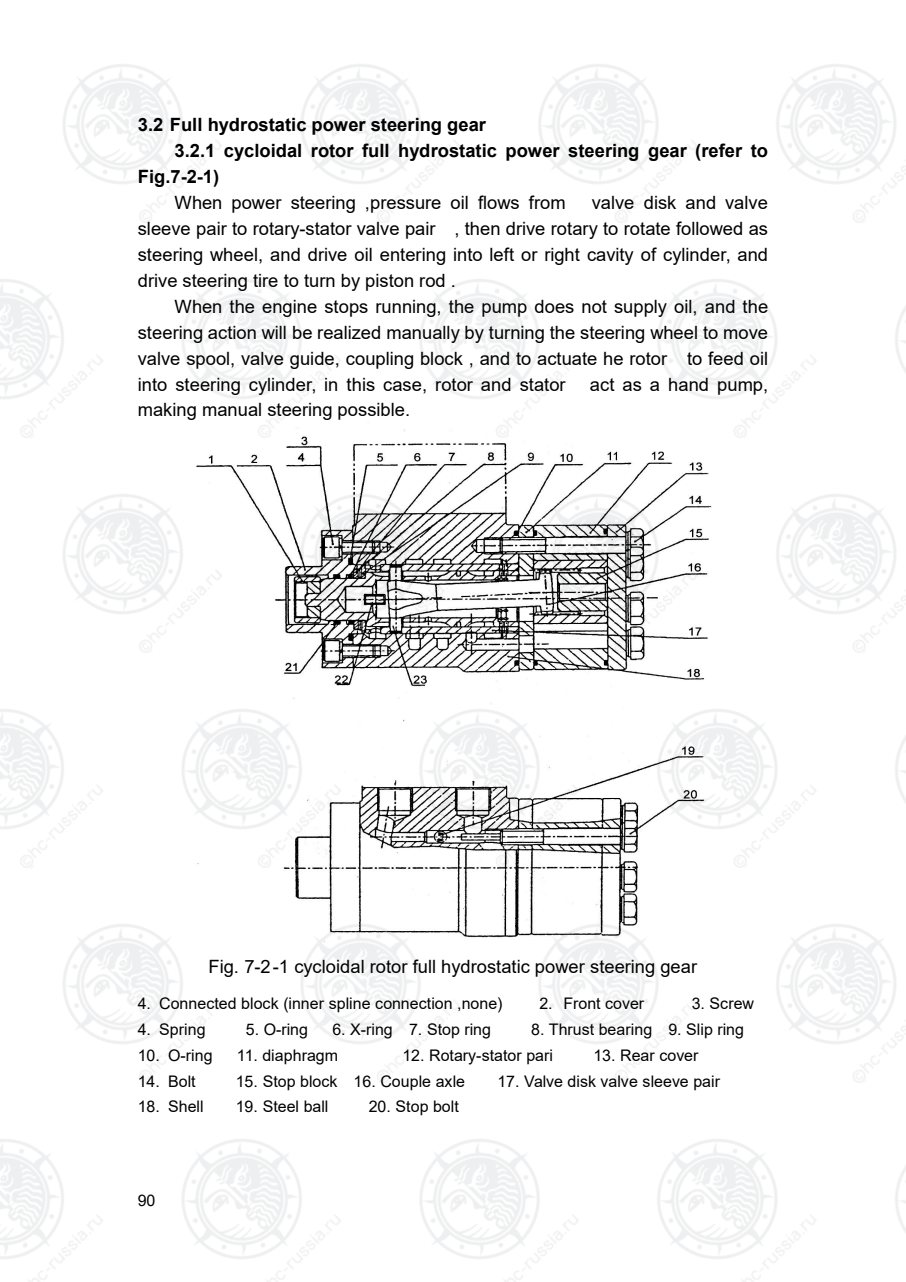
Страница 95
91
3.2.2 Load sensing type hydraulic steering gear (refer to Fig.7-2-2)
This hydraulic steering gear is load sensing type. There is a LS mouth in the steering
gear connected to priority valve that makes steering load pressure signal transmit to
priority valve through oil pipe, which controls the oil quantity supplied to the steering gear.
In the load sensing type steering system, whatever load pressure or steering wheel
speed, it can prioritize corresponding flow according to oil line requirement, and
guarantees the steering reliable, sensitive and light.
Besides the needed oil pump output flow to the steering system, the rest one is supplied
to working oil line, thus eliminates power loss from over oil supply to steering oil line, and
improves system efficiency.
When the power steering is working, pressure oil flows into rotor and stator pair through
valve element and valve pocket pair, and to drive rotor to rotate along with steering wheel,
and push oil into left and right chamber of steering cylinder, and piston rod pushes
steering tires to steer.
When the engine stops running, the pump does not supply oil, and the steering
action will be realized manually by turning the steering wheel to move valve element,
valve pocket, coupling, and to actuate the rotor to feed oil into steering cylinder, in this
case, rotor and stator act as a oil pump.
Displacement:125mL/r
Max. inlet pressure:16Mpa
Oil port sealing type:taper port sealing
Fig.7-2-2 Hydraulic steering gear schematic diagram
3.3 Steering cylinder
Steering cylinder is of double-acting piston type. The two end of piston is connected
with steering spindle through rod. The pressure oil from full hydrostatic power steering
gear makes piston rod to move left and right so as to turn truck lift and right.
Structure and maintenance, please see front part drive axle.
Оригинальная страница: таблицы и схемы
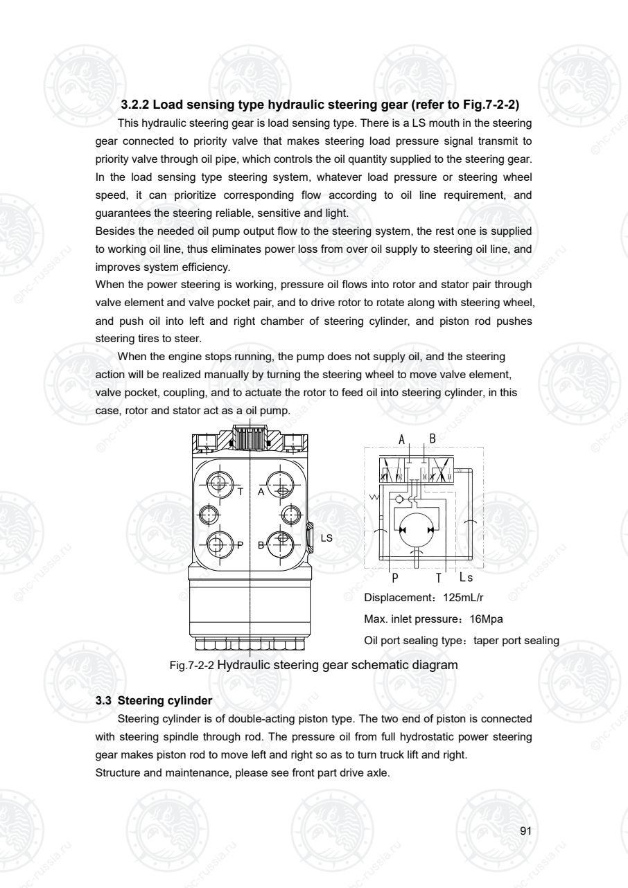
Страница 96
92
4. Install steering system
Careful observe the following:
3) Hydraulic tie-in, blots and piping must be cleaned while installing.
4) Check oil lines arrangement for properness, whether it is reverse order of
steering direction or not, refer to steering system .
5) Steer wheel to end left and right to make sure whether it is equably of
steering force and smooth of steering.
6) Jack up rear wheel and steer slowing wheel left and right and repeat it.
Bleed air of hydraulic lines and cylinder.
When engine stops running, rotate steering wheel with 1kg force slightly, after
leaving hands, steering wheel should be return 10° autobacking boardically.
Оригинальная страница: таблицы и схемы
Страница 97
93
Ⅸ. Brake system
1.Trouble and diagnoses and corrections
condition Probable cause Corrective action
Insufficient brake
force
·Oil leakage in brake lines.
·Air in brake lines.
·Water or oil on linings.
·Uneven wear or contact of brake linings.
·Improper functioning of master cylinder
or wheel cylinder.
·Clogged oil lines.
Correct and replenish.
Bleed air.
Clean or replace.
Grind or replace.
Correct or replace.
Clean.
Unequal braking
(forklift truck
veers to one
side)
·Uneven tire pressure.
·Brake out of adjustment.
·Water or oil on brake linings.
·Foreign particles in brake drum.
·Deteriorated lining surface.
·Improper contact of linings.
·Worn lining.
·Worn, warped, rusted or damaged
brake drums.
·Improper operation of wheel cylinder.
·Improper sliding shoes.
·Loose back plate blots.
·Warped back plates.
·Improperly adjusted wheel bearing.
·Clogged oil lines.
Adjust.
Adjust.
Clean or replace.
Clean.
Grind or replace.
Grind or correct.
Replace.
Correct or replace.
Correct or replace.
Adjust.
Tighten or replace.
Replace.
Adjust or replace.
Clean.
Brake dragging
·No free play of brake pedal.
·Improper shoe sliding.
·Improper operation of wheel cylinder.
·Faulty piston cup.
·Weak or broken return springs.
·Clogged master cylinder returns port.
·Clogged oil lines.
·Wheel bearing out of adjusting.
Adjust.
Adjust.
Adjust or replace.
Replace.
Replace.
Clean.
Clean.
Adjust or replace.
Brake noise.
·Lining surface harden or foreign
particles on it.
·Warped back plates or loosed blots.
·Brake shoes warped or improper install.
·Worn linings.
·Loose wheel bearing.
Repair or replace.
Repair or replace.
Repair or replace.
Replace.
Repair.
Оригинальная страница: таблицы и схемы
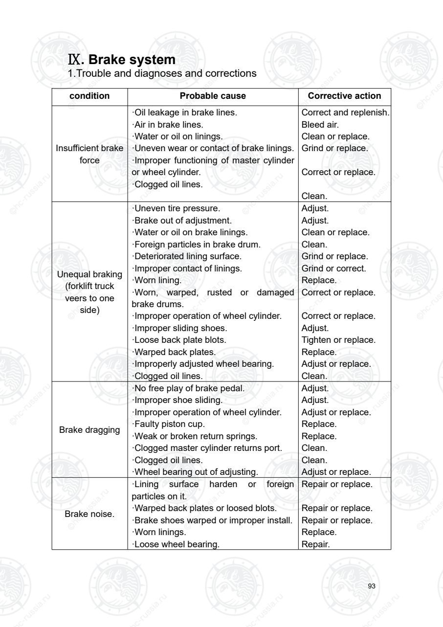
Страница 98
94
2. Summary
The brake system is the front two-wheel braking type consisting of a master cylinder,
brakes and brake pedal.
2.1 master cylinder
The 2t-3.8t master cylinder contains a valve seat, check valve, return
spring, primary cup, piston and secondary cup, which are kept in place with
stop washer and stop wire. The exterior of the cylinder is protected from dust
by means of a rubber dust cover. The piston is actuated through the push rod
by operation of the brake pedal. First, as the brake pedal, the push rod pushes
the piston forwards. The brake fluid in the cylinder flows back to the reserve
tank through the return port until the primary cup blocks up the return port.
After the primary cup passes the return port, the brake fluid in the cylinder is
pressurized and opens the check valve, flowing through the brake lines to the
wheel cylinder. Thus, each wheel cylinder piston is forced outwards. This
brings the brake shoes into contact with the wheel drum and slows or stops
the lift truck.. Meanwhile, the cavity caused behind the piston is filled with
brake fluid led through the return port and inlet port to lubricate the piston.
When the brake pedal is released, the piston is forced back by the return
spring. At the same time, the brake fluid in each wheel cylinder is pressurized
by the force of the brake shoe return spring, thus returning into the master
through the check valve. With the piston in its original position, the fluid in the
cylinder flows into the reserve tank through the return port. The brake fluid in
the brake lines and wheel cylinders has a residual pressure
proportioned(about 0.04MPa) to the set pressure of the check valve, which
makes each wheel cylinder piston cup securely seated to prevent oil leakage
and eliminates of vapor lock developing when the lift truck is sharply braked.
Brake principle of brake master cylinder of 1t-1.8t forklift is similar.
Fig. 8-1 Master cylinder
1. Lock nut 2. Rod 3. Duct cover 4. Light spring 5. Gasket ring 6. Primary
cup 7.Piston 8.main cup 9. Spring 10.Raffinate valve 11. Valve
seat 12.Cylinder body
Оригинальная страница: таблицы и схемы
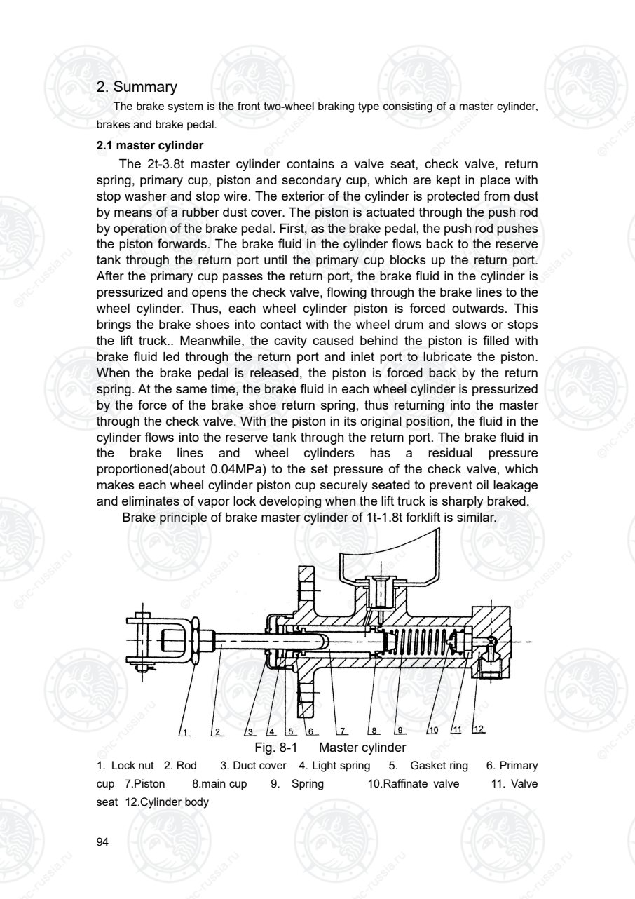
Страница 99
95
2.2 Brake
1t-1.8t ,3t-3.8t forklift right hand structure, please see fig. 9-2, 2t-2.5t structure
of forklift hand brake is similar to 3t-3.5t.
Fig. 8-2 1t~1.8t,3t~3.5t forklift truck right brake
1.Brake assy 2. Cap bleader 3. Screw,Bleader 4.Cylinder
5.Spring 6.Cup 7. Piston 8.Boots
9.Link,Conneeding 10.Pin 11.Brake lever 12.Plate,Shoe guide
13.Brake shoe 14.Elastic gasket 15. Retainer 16. Spring&fitting assy
17.Spring shoe 18. Cup,Shoe hold hown 19.Pin,Shoe hold down 20.Spring,Shoe hold down
21.Spring shoe, Rear left 22.Spring 23.Adjuster 27.Lever
28.Spring 29.Spring Pin 30.Guide,cable 31.Brake shoe
32.Spring, push rod 33.Push rod, Hand brake 34.Cable,Control 35.Plug,Rubber
36.Bolt M6×16 37.Washer 6 38.Spring shoe
Оригинальная страница: таблицы и схемы
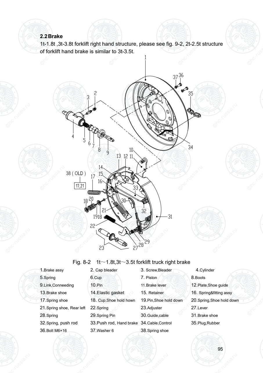
Страница 100
96
2.3 Replace brake shoe:
1) Place the forklift truck on level concrete.
2) Start engine and raise carriage about 100mm.
3) Place chocks behind rear wheels to prevent movement of forklift truck.
4) Loosen wheel nuts two or three turns each.
5) Tilt mast fully backward, and place a wooden block under each side of
outer mast.
△! WARNING:
Do not allow wooden blocks to touch front tires.
6) Tilt mast forward until front tires are raised from surface.
7) Support forklift truck by putting additional wooden blocks under each side
of front-end frame.
8) Stop engine.
9) Remove wheel tire nuts and brake drum. Remove half-shaft, lock nut, and
washer.
10) Remove wheel hub and brake drum.
11) Replace brake shoes with new ones.
12) Install brake drum.
13) Adjust shoe to drum clearance: rotate wheel counterclockwise and at the
time press down brake pedal several times.
14) Take out every padding block:take out according to reverse procedures
when inserting.
15) Make sure no person or obstacle is around forklift, then operate forklift in
reverse at 2km/h to 3km/h, set foot on brake pedal 2~3 times.
16)
2.4 Hand brake device
The hand brake device adopts a hand-pulling soft brake wire cable device. It
makes use of auto-assist pressure linings type brake together with foot brake.
Only when parking truck, use the hand brake. If it occurs for foot brake
malfunction, use hand brake to stop the truck.
Make sure that drive system is working normally before adjusting hand brake.
1) Adjust nut B to make the length L is 15.5mm, and then lock nut A
2) Adjust nut A to adjust hand brake pull force, the pull force of point P in Q
direction is in the range of 15kg~20kg when locking hand lever.
3) When the handle is locked, ensure that the E is not tilted。(The difference between S1
and S2 is less than 2mm);(Details refer to the view V)。
4)When the hand brake pull rod is in the locked position, the support of the brake cable
can not be tilted。If there is a tilt phenomenon, then re adjust the length of the L.
5) Make sure hand brake device work normally.
Оригинальная страница: таблицы и схемы
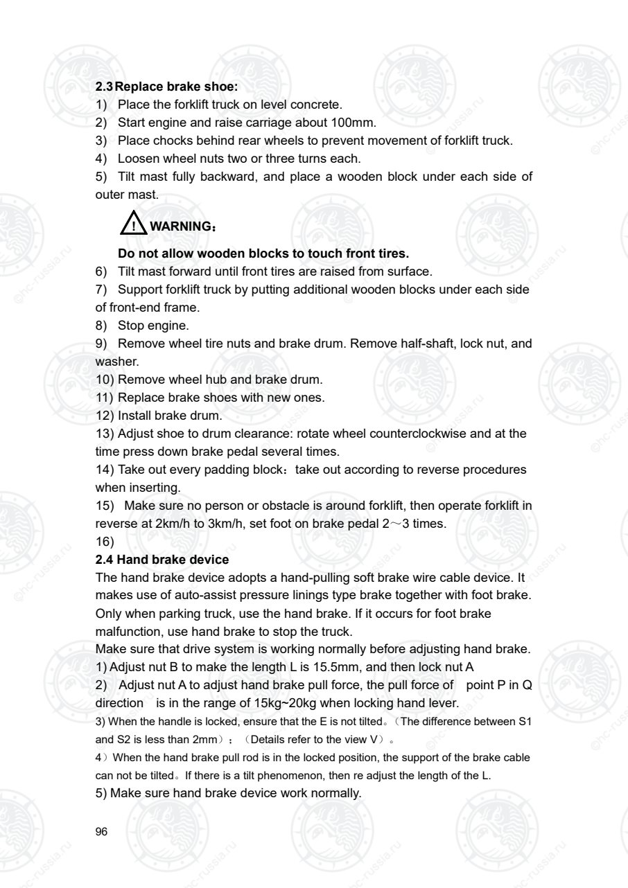
Страница 101
97
Notice: wipe lithium lubricating grease on guide rail C, and do it usually.
视图
B
A
松开
锁紧
压钮
Fig. 8-3 hand brake
3 . Brake schematic
Fig. 8-4 Brake schematic
view
The press button
Loose
Lock
Оригинальная страница: таблицы и схемы
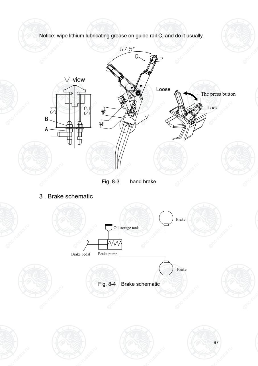
Страница 102
98
Ⅹ.Hydraulic system
1.Data
Main pump
1t-1.8t
type gear
driving Engine power take off type: gear
displacement( ml/r) 25
speed(r/min) 500~3000, 400~3500, 500~3000
Output pressure
(Rated/Max.)MPa
20/25
2t-3.8t
2t -3.8t
type gear
driving Engine power take off type: gear
displacement( ml/r) 26.5, 28.2, 30, 34
speed(r/min) 400~3500
Output pressure
(Rated/Max.)MPa
20/25
Оригинальная страница: таблицы и схемы
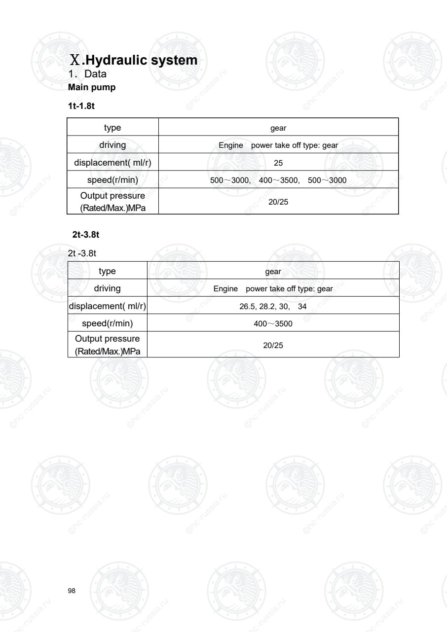
Страница 103
99
Control valve
1t-1.8t
Nominal pressure 20MPa
Rated flow 65L/min
Main relief valve
setting pressure
1.0t: 13MPa, 1.5t: 15.5MPa, 1.8t: 18.5MPa
Steering relief valve
setting pressure
8.8±0.25 MPa
Overload valve
setting pressure
16±0.25 MPa
Single stable shunt
valve
12 L/min ~14L/min
2t-3.8t
Nominal pressure 20MPa
Rated flow 65L/min
Main relief valve
setting pressure
18.5±0.25 MPa
Steering relief valve
setting pressure
8.8±0.25 MPa
Overload valve
setting pressure
16±0.25 MPa
Single stable shunt
valve
12 L/min ~14L/min
2.Trouble diagnoses and corrections
Main pump
trouble Probable cause Corrective action
No oil from oil
pump
Low oil level in tank. Add oil to specified level.
Clogged suction pipe or
strainer.
Clean oil line and tank. If oil is dirty,
change.
Low
discharge
pressure on
oil pump.
Worn bearing, damaged
backup ring and O-ring.
Replace faulty parts.
Maladjusted relief valve. Readjust to specified pressure using
pressure gauge.
Оригинальная страница: таблицы и схемы
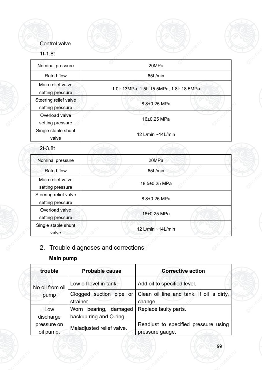
Страница 104
100
trouble Probable cause Corrective action
Air in oil pump.
Retighten suction side pipe.
Add oil in oil tank.
Check pumps oil seal.
Do not operate pump until bubbles in
tank disappear.
Noisy oil
pump
Cavitation due to crushed
suction hose or clogged
strainer.
Adjust or replace crushed hose and
clean strainer.
Air being sucked from
loose suction side joint. Retighten each joint.
Cavitation due to too high
oil viscosity.
·replace with new oil having proper
viscosity for temperature at which
pump is to be operate.
·to operate when oil temperature is
normal.
Bubbles in hydraulic oil. Determine cause of bubbles and
remedy.
Oil leaking
from oil pump
Faulty oil seal on pump,
faulty O-ring or worn
sliding surfaces on pump.
Replace faulty parts.
Control valve
Trouble Probable cause Corrective action
Pressure of
relief valve is
not steady or
too low.
Loose of pressure-adjust screw. Readjusted and retighten.
Distorted or damaged
pressure-adjust spring. Replace.
Worn or blocked relief valve core. Replace or clean.
Pump abated. Examine and repair pump.
Fork tilt forward
when control
lever is used
while engine is
off.
Worn or damaged tilt lock valve. Replace valve core and tilt lock
valve as an assembly.
Broken tilt locks spring. Replace spring.
Damaged tilt valve plunger O-ring. Replace O-ring.
Mast is unstable
when tilting
forward.
Malfunctioning tilt relief valve. Replace tilt relief valve
assembly.
Lowering Valve body and spool valve is Replace spool valve with
Оригинальная страница: таблицы и схемы
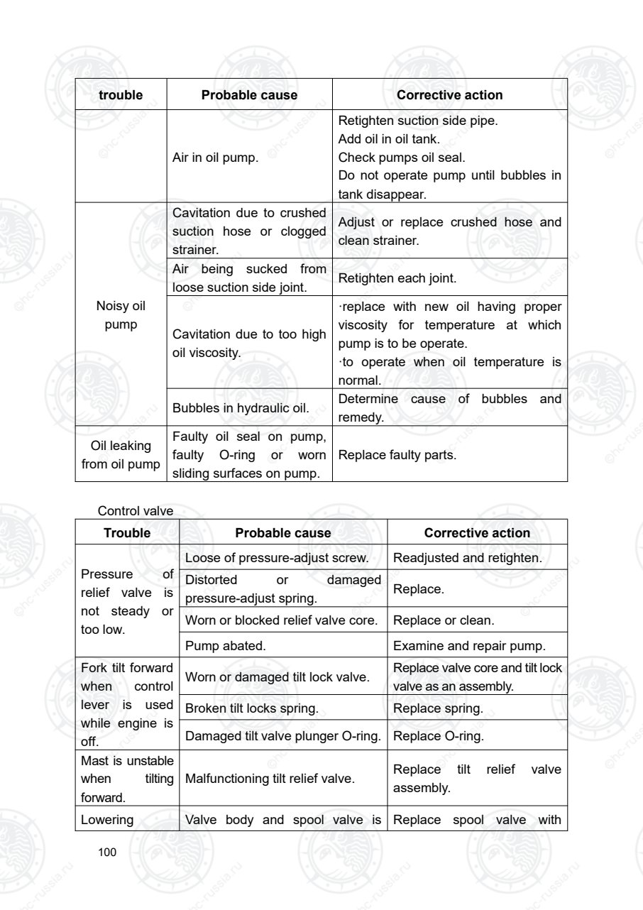
Страница 105
101
distance of
mast is big
when spool
valve is in the
centre.
worn and clearance between
them is too great.
specified clearance.
Spool valve is not in centre. Keep being in the centre.
Cylinder seal abated. Examine and repair cylinder.
Taper valve is worn or blocked by
dirt. Replace or clean taper valve.
Spool valve is
not return
neutral position.
Damaged or distorted
reposition-spring. Replace spring.
Dirt exist between valve body and
spool valve. Clean.
Blocked control device. Adjusted.
Not coaxial parts at reposition Reinstall.,be coaxial
Leakage
Damaged O-ring. Replace.
Faulty seal of joint. Check and retighten.
Loose seal plate. Clean seal plate and
retighten blots.
Loosed lock-nut of relief valve and
connect-nut between plate and
plate.
Tighten.
3. Main pump
3.1 W21 main pump
1-1.8t W21 main pump is a gear type consisting of a pump body, pump cover,
a pair of gear, bearing and seal ring. This pump uses pressure-balance type
bearing and a special lubrication method so as to get the minimum clearance
of the gear flank.
Since the pump body and cover are made of aluminum alloy, they are light
and rigid. The drive gear and driven gear are integrated with their respective
shafts, which are held against the pump body with bearing. The bearing, made
of special material, serves both as bearing for each shaft and as side plates
for the gear flank.
At the drive shaft side, an oil seal is press-fitted into the pump body to provide
oil tightness performance. Oil tightness between pump body and pump cover
is secured with a packing of a special shape.
Main pump maintenance remove (refer to Fig.9-1)
f. Hold the pump in a vice lightly and remove blot 12.
Оригинальная страница: таблицы и схемы
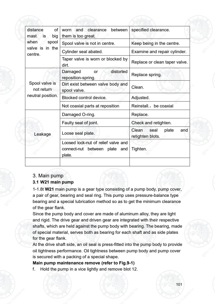
Страница 106
102
g. Remove pumps cover 1 and remove seals 8, 9, 10 and 11.
h. Remove forward end-cover 7, 8, 9, 10 and 11.
i. Remove bearing 3, 4 and gear 5, 6 from pump body 2. If remove bearing
difficult, you can press gear.
j.For the convenience of correct reassemble, it is to put the disassembled
parts as shown in Figs.9-1.
Fig. 9-1 clockwise gear pump
1.End cover 2. Gear plate 3. Bearing 4. Bearing 5. Driving gear
6. Driven gear 7. Front end cover 8. Seal ring 9. Seal ring 10. Seal ring
11. Seal ring 12. Bolt 13. Lock washer 14. Oil seal 15. Snap ring
3.2 2t-3.8t main pump
2t-3.8t hydraulic system adopts CBHZG model gear pump. Gear pump
CBHZG is an external gear pump with axial interval self-compensation and
radial hydraulic balance. By using special structure, low noise comparing with
those in symmetry. backing boarderials used in the parts effectively improve
the performance and make it reliable, i.g, DU sleeve in bearing, double metal
backing boarderial of side plate, AL. alloy die casting of front and rear cover,
extruding AL. alloy of middle section, etc.
CHBZG left rotation see fig. 9-2, right rotation see fig. 9-3.The difference of
counter-clockwise and clockwise pump is 3 shape backing plate. The direction
of them is different.
Clockwise
Оригинальная страница: таблицы и схемы
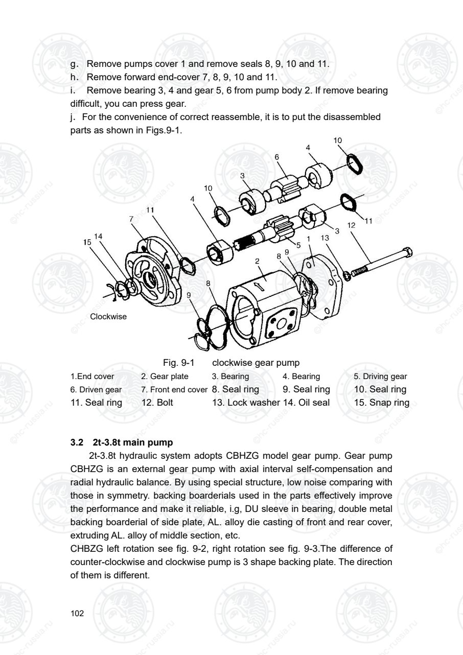
Страница 107
103
Fig. 9-2CBHZG counterclockWise rotation gear pump (left)
1. Snap ring 2. Oil seal 3. Mounting flange 4.Seal plate
5. 3 shape backing plate 6. Pressure plate 7. Bush
8. Driven gear 9. Drive gear 10. Gear plate 11. End cover
12. Washer 13. Mounting bolt
Оригинальная страница: таблицы и схемы
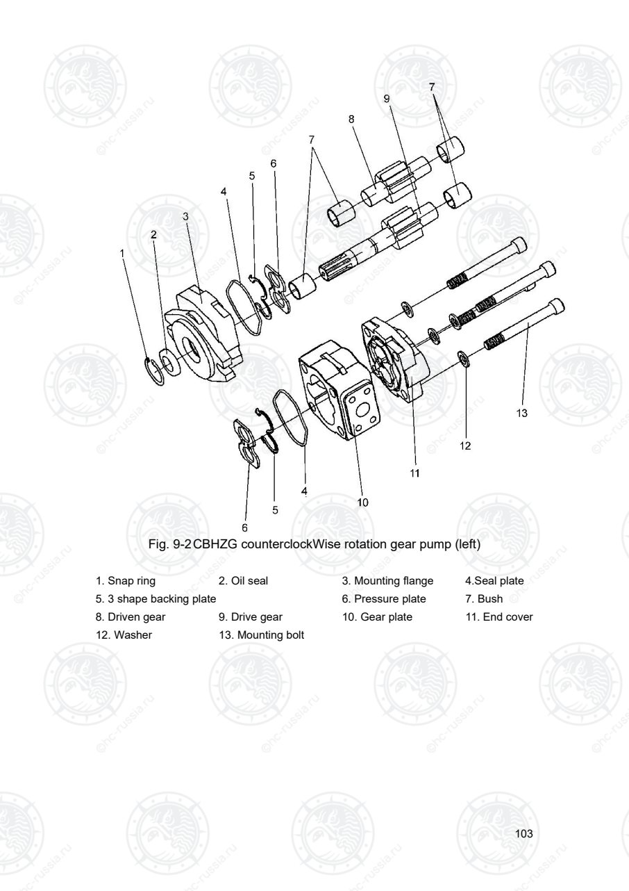
Страница 108
104
Fig. 9-3CBHZG clockwise (Right) rotation gear pump
1. Snap ring 2. Oil seal 3. Mounting flange 4.Seal plate
5. 3 shape backing plate 6. Pressure plate 7. Bush
8. Driven gear 9. Drive gear 10. Gear plate 11. End cover
12. Washer 13. Mounting bolt
Оригинальная страница: таблицы и схемы
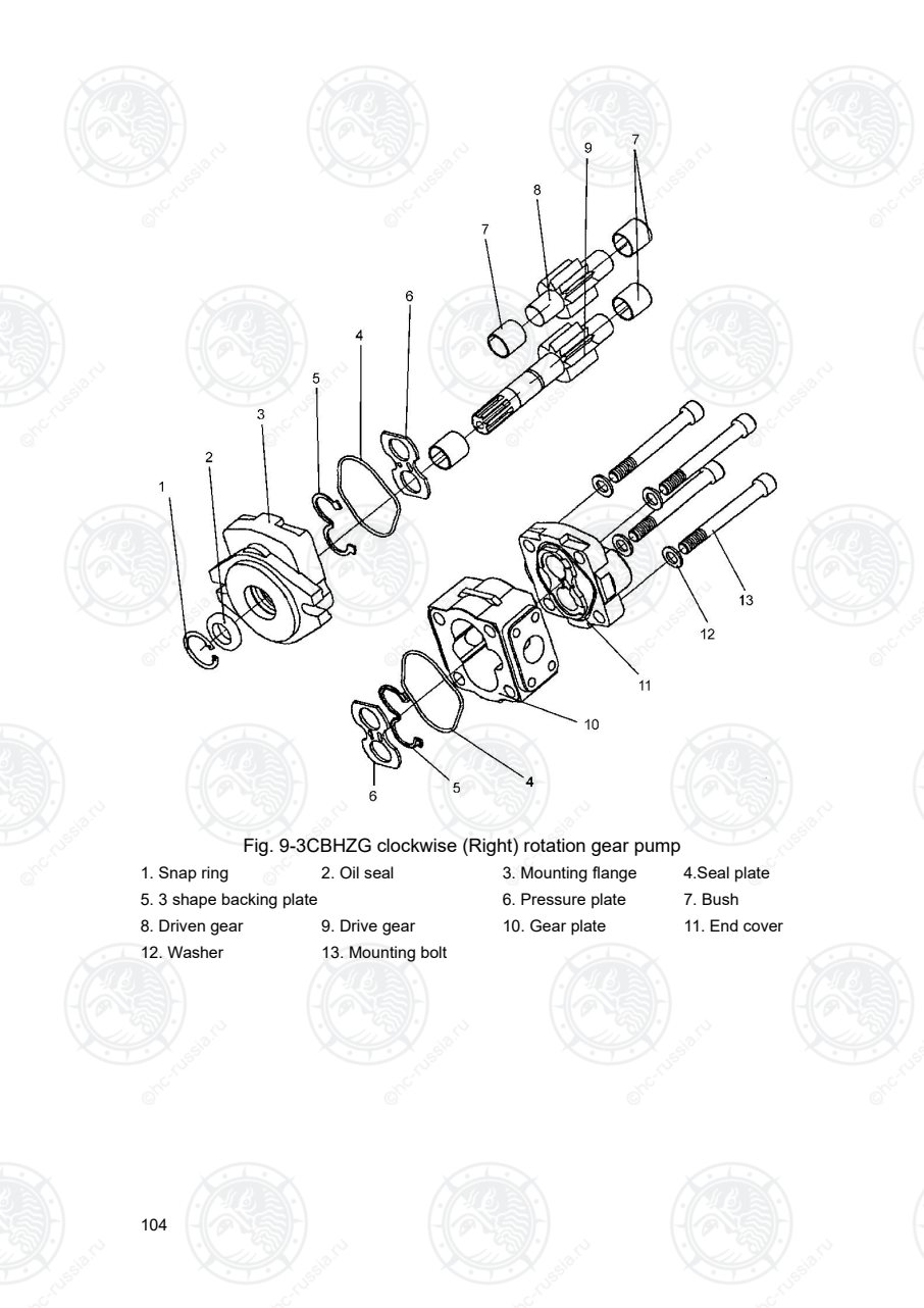
Страница 109
105
4. Control valve
Two pieces type control valve consists of four pieces of valve body, two
plungers, a relief valve and a divided valve. Four pieces of valve body are
assembled with three blots and nuts. Tilting plunger is fitted by tilting lock-self
valve. According to requirement of work device, it is capable to add combined
lock vale and rotating valve.
Fig.9-4-1 Control valve for 1t~3.5t forklift truck(for cycloidal rotor full
hydrostatic power steering gear)
Оригинальная страница: таблицы и схемы
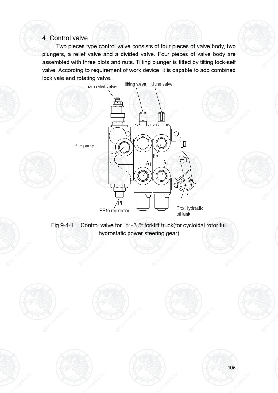
Страница 110
106
Fig.9-4-1 Control valve for 1t~3.5t forklift truck(Load sensing type hydraulic
steering gear)
4.1 Main relief valve and flow dividing valve
Main relief overflow valve is consisting of main valve A and guide valve B.
When shifting of control valve, C house connects with high pressure oil of
working mechanism (lifting cylinder, tilting cylinder). By fixing throttle hole D
and E, pressure oil acts on guide valve B. When oil pressure of lines is higher
than setting pressure of oil lines, guide valve B opens to low oil pressure of F
house and main valve spool A moves right to connect pressure oil to low
pressure lines G and C house unload. To ensure stability of oil pressure of
lines, adjusting screw H can adjust stable pressure valve of whole lines.
The structure of dividing valve is simple which is straight-move type
overflow. Using the principle that liquid pressure balance with spring pressure
to decide stable pressure value of steering system. When operating steering
wheel, house M connects with high pressure oil lines. In that case, when line
pressure is higher than spring pressure, valve spool N move right and
pressure oil connects with lower pressure line by T house to unload M house.
To ensure stability of steering system, adjusting screw K can adjusting stable
value of whole system.
L valve is balance spool, by constant changing of flow volume and oil
pressure, spool L moves left and right so as to not alter the opening of R A and
S to ensure flow volume between entering working house Q and exit PS and
Оригинальная страница: таблицы и схемы
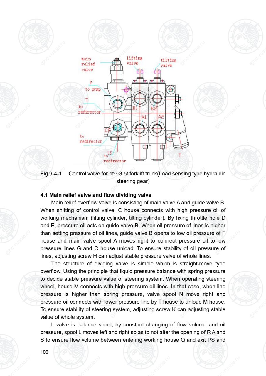
Страница 111
107
full hydrostatic power steering gear balances automatically and divide liquid
stable pro rata. A, b and c are fixing throttle hole.
Fig. 9-5
4.2 Adjusting the pressure of the main relieve safety valve
The main relieve valve has been adjusted before leaving the factory, , it is not allowed to
adjust at will in general condition. Adjusting way is as follows:
(1) Park the truck on solid and smooth road, place in neutral, pull up the hand brake
handle, tilt the mast backwards to the end, and drop the fork to the ground. The
engine stops.
(2) Open front soleplate, release the pressure mouth bolt of oil inlet pipeline in the
multi-way valve, and put in clean place. If hydraulic oil outflows, please protect the
environment.
To redirector
Oil-return
Oil-input
Main safety valve
Flow divide safety valve
Оригинальная страница: таблицы и схемы
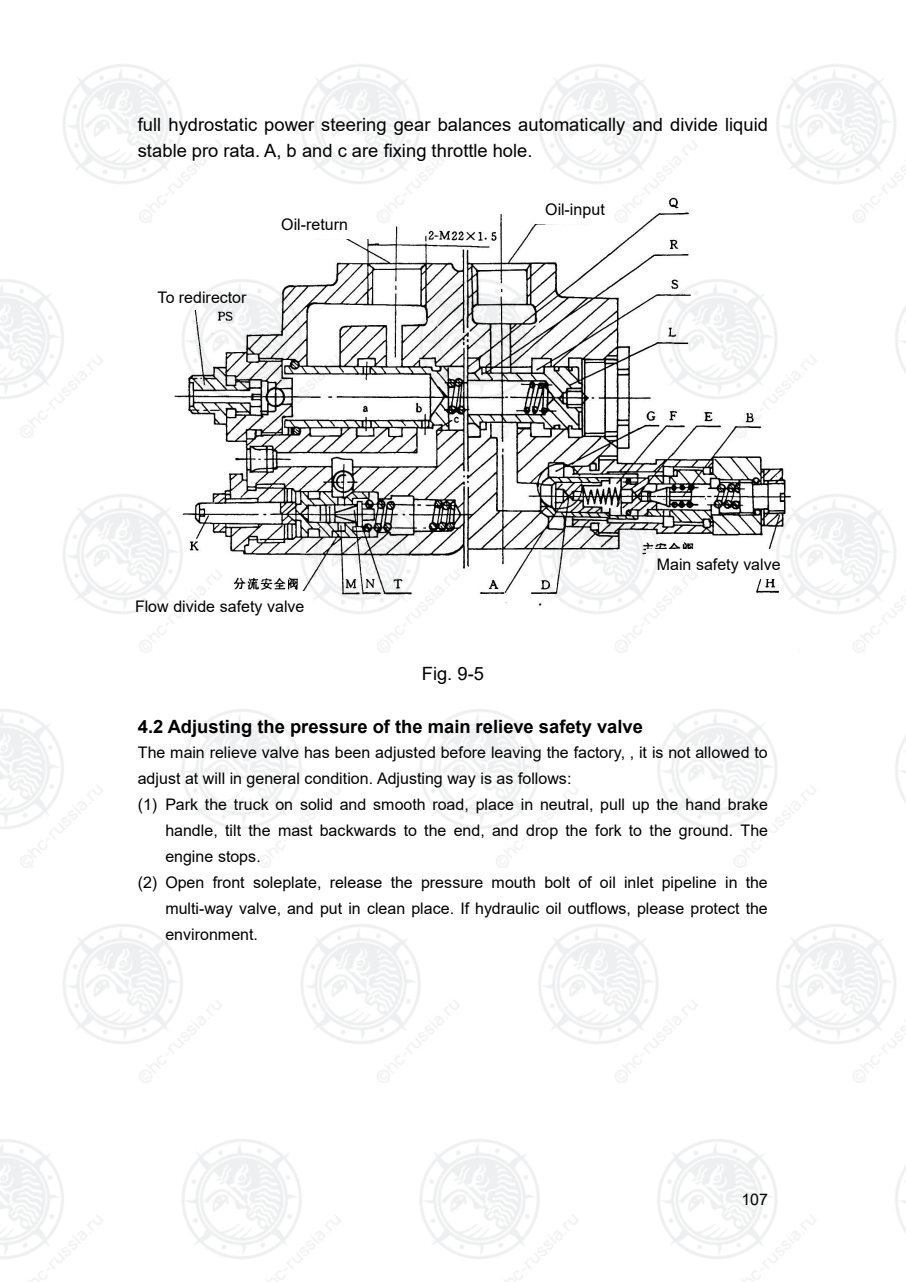
Страница 112
108
+
-
(3) Connect the pressure gauge. Notice: a. Specification of gauge should be larger than
20Mpa. b. taper thread at pressure mouth matches: Rc1/8R1/8; c. tightening torque is
20N•m-22N•m.
(4) Start the engine, place the mast in vertical, and the fork is 300mm from the ground.
(5) Read out the indication in the pressure gauge, and judge is the main safety valve of
multi-way valve is in normal scope.
1.0t: 13MPa, 1.5t:15MPa, 1.8t:18.5MPa, 2.0t~3.8t:18.5MPa±0.25 MPa
(6) If the pressure is not in the normal scope, please release the main safety valve lock
nut, and adjust adjusting bolt.
If the indication is smaller than the normal scope, inner hexagon spanner the
adjusting bolt in clockwise (+) to increase main safety valve pressure.
If the indication is larger than normal scope, inner hexagon spanner the adjusting bolt
in counterclockwise (-) to decrease main safety valve pressure.
(7) Stable the pressure in normal scope for 30’s.
(8) Release pressure gauge, install the bolt, and the tightening torque is 20N•m-22N•m.
Drop the mast to the ground and tilt backward to end.
(9) Retighten the tightening nut, and fix it on the front soleplate.
4.3 Operation of tilt lock valve
Tilting lock valve is fitted by lock-self valve to prevent vibration owing to
back pressure inside tilt cylinder and avoid casualty because of
miss-operation. According to common structure, it can operate tilt spool to tilt
forward after engine is off, but using the tilt lock valve, when engine is off, it
cannot tilt mast forward even push the lever of operation valve, the structure is
shown as Fig. 9-6.
Connector of valve body: “A”,“B” connects separately with frond and rear
house of tilt cylinder piston. When pulling out spool, high pressure oil (P)
enters connector “A”, oil in rear house returns to oil tank (T), in this time mast is
in tilting backward.
When pulling tilting spool, high pressure oil enters connector “B”, by high
pressure oil, lock valve in spool works to make “A” to connect with low
Оригинальная страница: таблицы и схемы
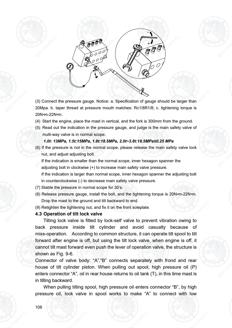
Страница 113
109
pressure. When engine is off or stop, lock valve in spool cannot work without
high pressure oil, so that connector “A” can not connect low pressure line and
mast cannot tilt forward, also there is not back pressure in tilt cylinder.
5. Hydraulic piping
5.1 Cycloidal rotor full hydrostatic power steering gear
The high pressure oil from main pump goes to control valve and divide it
to two parts by priority valve inside control valve: one of them preferentially
goes to steering gear control steering cylinder, excess part goes to lifting
cylinder or tilting cylinder. When lifting and tilting spool is in neutral, high
pressure oil return oil tank directly from pass way. When pulling lifting spool,
high pressure oil goes by throttle valve and then push piston rod under lifting
cylinder piston. When pushing lifting spool, it is that bottom of lifting cylinder
piston connects with low pressure line and then piston rod drops by
deadweight and weight of cargo. In this time, oil from lifting cylinder goes by
unidirectional speed limiting valve so as to control the falling speed. When
operating tilting spool, high pressure oil goes to front house of tilting cylinder
and another connects with low pressure line so as to make mast tilt forward or
backward.
The cut off valve is used under right lifting cylinder, its function is to prevent
goods falling suddenly when oil pipe is busting.
Оригинальная страница: таблицы и схемы
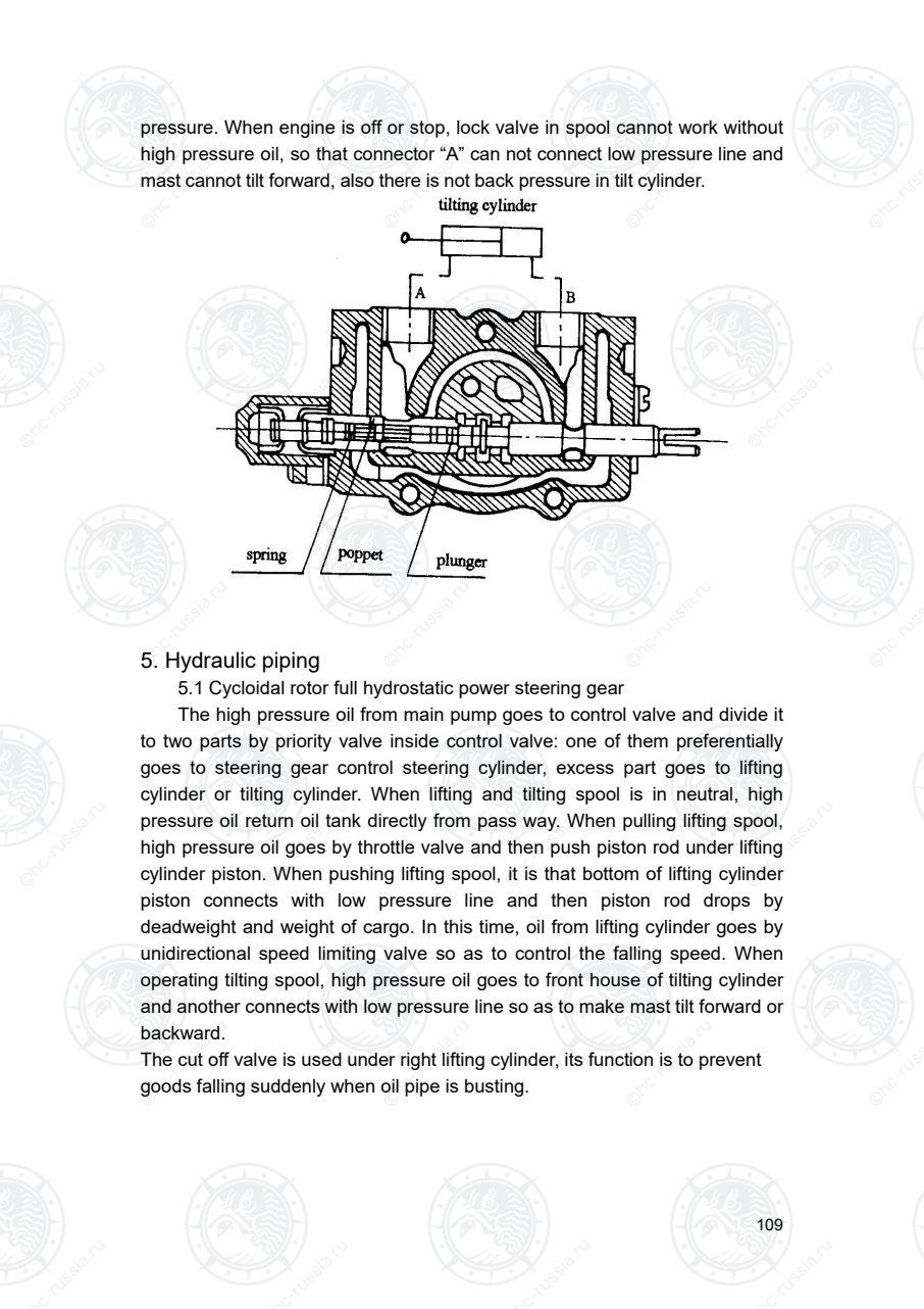
Страница 114
110
Fig. 9-7-1 Schematic figure of hydraulic system
Оригинальная страница: таблицы и схемы
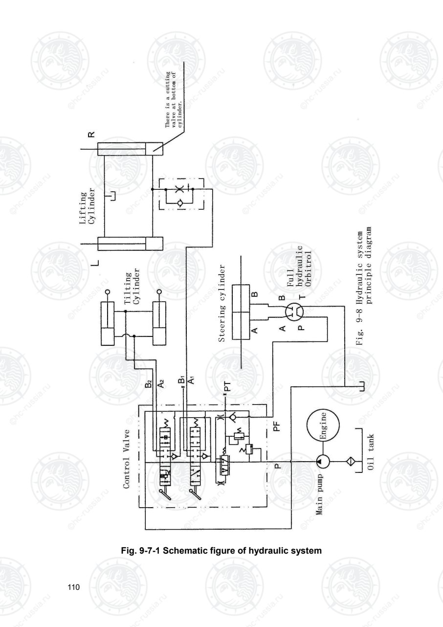
Страница 115
111
5.2 The high pressure oil from main pump goes to control valve and
divide it to two parts by priority valve inside control valve: one of them
preferentially goes to steering gear control steering cylinder, excess part goes
to lifting cylinder or tilting cylinder. When lifting and tilting spool is in neutral,
high pressure oil return oil tank directly from pass way. When pulling lifting
spool, high pressure oil goes by throttle valve and then push piston rod under
lifting cylinder piston. When pushing lifting spool, it is that bottom of lifting
cylinder piston connects with low pressure line and then piston rod drops by
deadweight and weight of cargo. In this time, oil from lifting cylinder goes by
unidirectional speed limiting valve so as to control the falling speed. When
operating tilting spool, high pressure oil goes to front house of tilting cylinder
and another connects with low pressure line so as to make mast tilt forward or
backward.
The cut off valve is used under right lifting cylinder, its function is to
prevent goods falling suddenly when oil pipe is busting.
Оригинальная страница: таблицы и схемы
Страница 116
112
Fig. 9-7-2 Schematic figure of hydraulic system
Оригинальная страница: таблицы и схемы
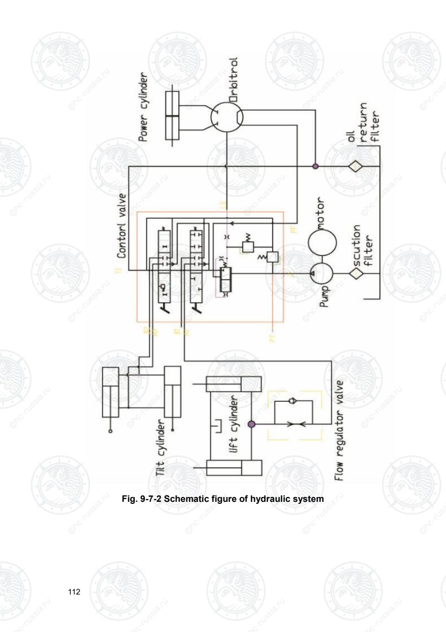
Страница 117
113
Ⅺ.Lifting system
1. Assemble debugging data
Debugging data Double mast and triple mast
Mast type
Standard type and
lifting height of >2~4
meter
Lifting height
>4~5 meter,
TRIPLEX
MAST 4 meter
Lifting height
> 5~6 meter
Mast tilt
angle
Forward 6° 6° 3°
Backward 12° 6° 6°
Fork carriage roller Complex rolle assy, Side roller assy, Cross roller assy
Inspection and adjustment
Place Assembly clearance
(mm)
Repair clearance(mm)
Mast to lift roller 0.1~0.8 0.2~1
Shims 0.5,1.0,2.0
Mast to back up metal 0.1~0.8 0.2~1
Shims 0.5,1.0
Inner mast to carriage
side roller 0.1~0.6 0.2~1
Shims 0.5,1.0
Lift chain deflection 25~30 mm
Tightening torque
Place Model or Lifting capacity N·m
Lift chain lock nut 1-1.8t 193-257(M16)
2~3.8t 245-314(M20)
Mast support cap blot 1-1.8t 124-165(M14)
2~3.8t 176-216(M18)
Tilt cylinder lock nut 1-1.8t 89-118(M14)2~3.5t
Lift cylinder bolt(top) 1-1.8t 76-107(M12)2~3.8t
Lift cylinder bolt(bottom) 1-1.8t 22-30(M8)2~3.5t
Lift cylinder fixing
bolt(cylinder light bolt)
1-1.8t 76-107(M12)2~3.8t
Оригинальная страница: таблицы и схемы
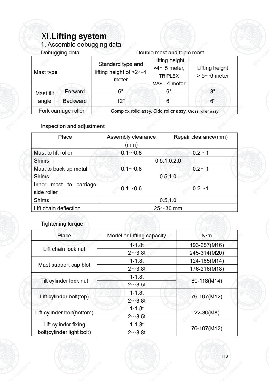
Страница 118
114
Basic model mast weight
Model(truck) 1t 1.5 t 1.8t 2t 2.5t 3t 3.5t-3.
8t
Weight(mast) kg 531 531 540 575 644 721 820
2. Trouble diagnoses and corrections
Condition Probable cause Corrective action
Fork arm carrier or mast tilt
by itself.
1.Tilt cylinder and ring abraded
excessively
Replace piston ring tilt
cylinder.
2. The hydraulic control valve
spring is inoperative.
Replace it.
The fork arms carrier
moves up and down
sluggishly.
1. Caused by piston jamming or
bent piston rod.
Replace the faulty parts.
2. Too much dirt is accumulated in
the cylinder.
Strip it down and clean.
Forks are lifted or lowered
non-smoothly.
1. Carriage bracket assembly out of
adjustment.
Adjust clearance with thrust
metal and carriage side
roller.
2. Insufficient clearance between
inner and outer masts or rollers and
mast.
Adjust clearance with
rollers.
3. Biting foreign backing
boarderials between moving part.
Remove foreign backing
boarderials.
4. Insufficient lubrication.
Apply grease on contact
surfaces of sliding
parts.(butter)
5. Bent carriage bracket assembly. Repair or replace.
Forks are lifted unevenly 1. Lift chains out of adjustable. Adjust lift chains.
Lift roller does not rotate
1. Grease stiffened or dirt
accumulated on lift roller and mast
sliding surfaces.
Clean and lubricate lift
rollers.
2. Improperly adjusted lift roller. Adjust.
Excessive mast noise
1. Insufficient lubrication. Lubricate.
2. Improperly adjusted lift roller,
side roller and back-up metal.
Adjust.
Оригинальная страница: таблицы и схемы
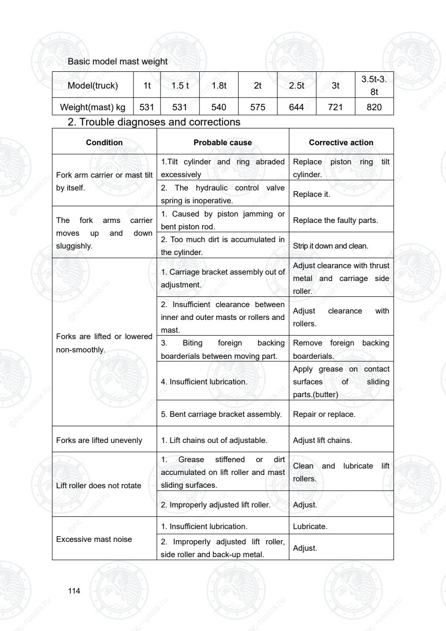
Страница 119
115
Condition Probable cause Corrective action
Insufficient lift power or no
lift movement.
1. Excessive wear occurs between
the oil pump body and gears,
causing too much clearance.
Replace the worn parts or
the oil pump.
2. The lifting jack piston Yx-ring has
worn, resulting in excessive inner
leaks.
Replace Yx-ring.
3. Springs of the multiple control
valve and its relief valve are
inoperative oil leaks.
Replace.
4.Excessive wear occurs of the
hydraulic
control valve, resulting in excessive
oil leaks.
Replace.
5. Oil leaks occur between the
hydraulic control valve sections.
Dismantle for regrinding the
joint surfaces and
reassemble the valve.
6. Leakage occurs in the hydraulic
pipe.
Tighten the joint nuts and
inspect the seal for
damage.
7. The hydraulic oil temperature is
too high. Oil viscosity is too low and
the rate is insufficient.
Change the wrong
hydraulic oil or stop
operation for reducing the
oil temperature. Find out
the reasons for high oil
temperature and eliminate
the trouble.
8. The load carried is beyond the
designed capacity.
Observe the lifting capacity
limit.
Оригинальная страница: таблицы и схемы
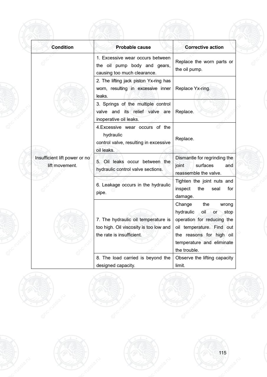
Страница 120
116
XR30M300-000000-000 Lifting Mast assembly
Tightening torque See foregoing table
3. Summary
The lifting system is composed of inner and outer mast, fork arm carrier,
fork arm, load backrest, chain, roller, lifting jack, and tilt cylinder, etc. Oil line
system, hydraulic pressure system and it compose fork lift truck work
equipment. This equipment is performing framework of load and unload.
Commonly common masts have simple mast, Double mast and Triple mast
class mast framework type. Fork lift truck what is made in our company
Оригинальная страница: таблицы и схемы
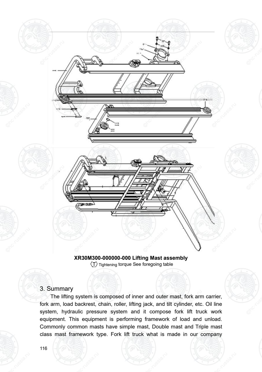
Страница 121
117
backing boardch Double high visibility mast, Double full free lift mast
(including container mast), Triple full free lift mast, mast framework adopted is
CL model juxtaposition roller type.
3.1 Simplex mast
Simplex mast is composed of outer mast which can’t lift and inner mast
which can lift. Lifting jack bottom is fixed on outer mast below cross beam,
oriented with screw. Piston rod extremity is joined with upper cross beam of
inner mast; cylinder body is fixed on outer mast fixation board with U-bolt.
Commonly free lift range is 155mm~170mm, which is difference with different
tonnage. Two lifting jacks (fig.10-5 is right) are laid out back of outer mast to
realize high visibility; two lifting jacks are laid outside of outer mast.
Forks are hung on the fork carriage by means of hooks, with longitudinal
roller set, composite roller set (ie, side-force slider set in the middle of the
longitudinal roller side) and side roller set (1-1.5t forklifts lack one and use
longitudinal roller group) on the fork carriage. Longitudinal roller set is installed
on the top of the outer mast and bottom of the inner mast. Composite roller set
is used on the top of the outer master for 1-1.8t forklifts.
Pressure oil from hydraulic control valve is entered into lifting jack by
unidirectional speed limiting valve, forced piston and piston rod rising, thereby
forced inner mast rising. At the same time one end of lifting chain on inner
mast is fixed on outer mast, the other is joined with fork arm carrier. Fork arm
carrier and fork arm is rising with inner mast rising to realize aim of lifting
goods.
It is basis model that our company offers forklift truck which lift 3 meter
high. It is especial model that our company offers forklift truck which lift height
else (2~6 m).
3.2 Double full free lift mast (including container mast)
Double full free lift mast (Fig10-2) is also composed of inner mast, outer
mast, fork arm carrier, and etc, is also belong to high visibility mast. It is
different from common standard type mast that two postpose long lifting jacks
are both pole stopper type cylinder. One piston rod is hollow, hole of piston rod
is dypassed for hydraulic pressure oil flowing into free lifting jack. End of
piston rod in two long lifting jacks is joined with upper branch of inner mast.
Besides, short lifting jack who is installed middle of inner mast is named as
free lifting jack. Free lifting jack is also pole stopper type cylinder.
Fork arm can rising or falling when height go beyond 1050mm, because
inner mast don’t rising when free lifting jack rising or falling. There are different
specifications in this series of height, 2.0m,2.5m, 2.7 m, 3 m, 3.3m,3.6,3.7, 4
m and etc. Free lifting height is commonly about 1050~2050mm.
When lowest height of mast ≥2190mm, lift height is 3m, full free lift height
Оригинальная страница: таблицы и схемы
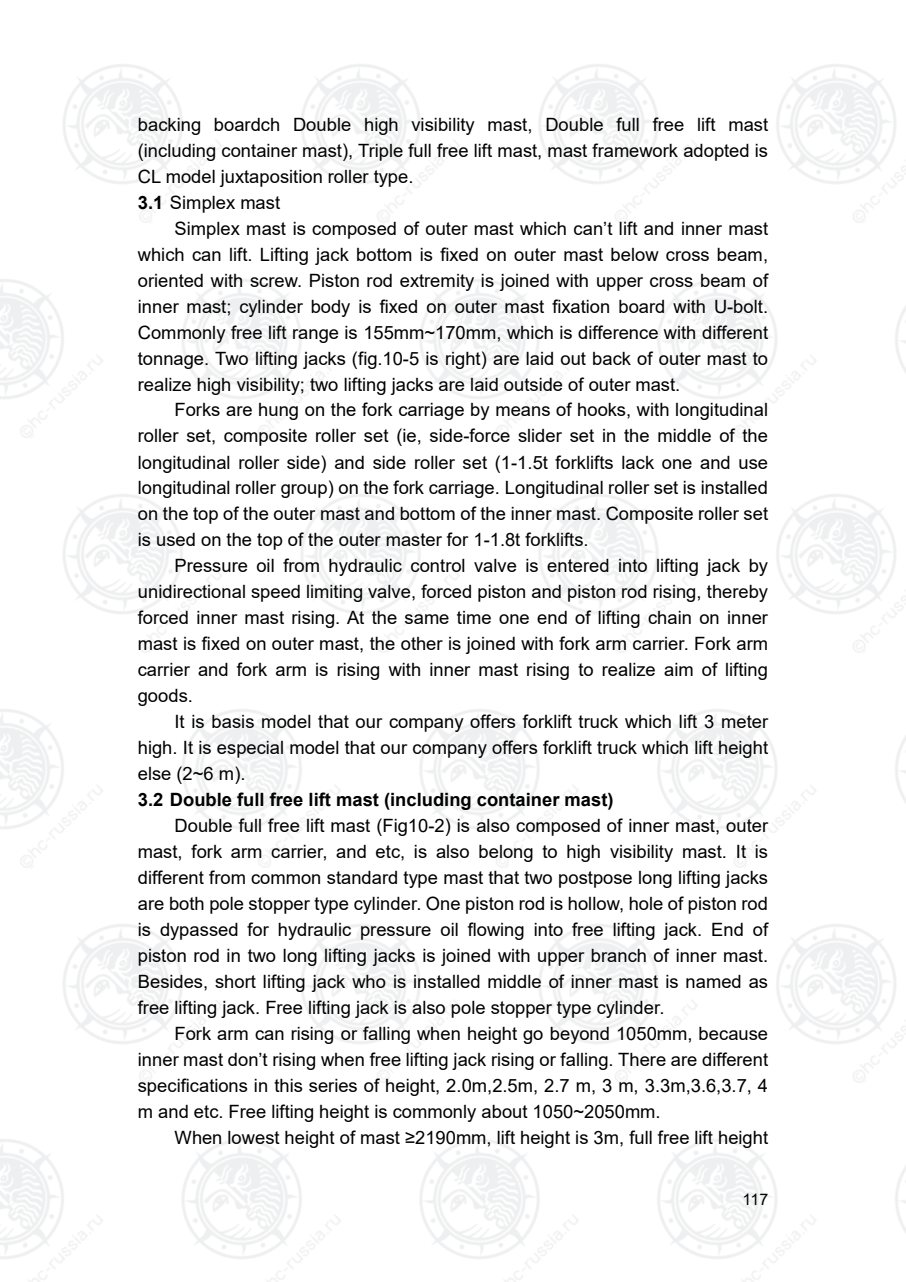
Страница 122
118
is about 1270mm. It can work inside container,mast which include side-shift is
named container fork lift truck mast (see Fig.10-3). Side shift cylinder of
container fork lift truck mast can be side shifting only when goods don’t placed
appropriate position. In another condition, side cylinder should set center.
Structure of left and right lifting cylinder of more than or equal to 3 t, see
fig.10-6, fig.10-7;
Structure of left and right lifting cylinder of less than or equal to 2.5 t,see
fig.10-6, fig.10-8.
3.3 Triple full free lift mast
Triple full free lift mast (fig.10-4) is composed of outer mast, middle mast,
and inner mast, middle mast and inner mast can flex. There are different
specifications in this series of height, 4m, 4.3m, 4.5m, 4.7m,4.8m, 5m, 5.5m,
6m, 6.5m, 7m, etc. It is different from double full free mast that mostly it
includes middle mast, and its two postpose long lifting jacks are both piston
type cylinder
(fig.10-5), and its oil system rather complex than oil system of double full
free mast. Free lift cylinder structure see fig.10-6.
Fig. 10-1 Double stage wide view mast
1. Outer mast 2. Inner mast 3. Load-backrest 4. Fork arm carrier
5. Fork arms 6.Chain 7.Left lifting cylinder 8.Right lifting cylinder
9. Tilting cylinder
Оригинальная страница: таблицы и схемы
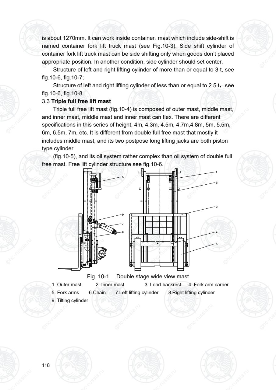
Страница 123
119
Fig.10-2 Double grade full free lifting mast
1.Outer mast 2. Inner mast 3. Chain 4. Free lifting cylinder 5. Fork arm
carrier 6. Fork arms 7.Left lifting cylinder 8.Right lifting cylinder 9. Load-backrest
10. Tilting cylinder
Fig.10-3 Containers forklift mast
1.Outer mast 2. Inner mast 3. Chain 4. Free lifting cylinder 5. Fork arm
carrier 6. Fork arms 7. Side move cylinder 8.Left lifting cylinder 9.Right
lifting cylinder
10. Load-backrest 11. Tilting cylinder
Оригинальная страница: таблицы и схемы
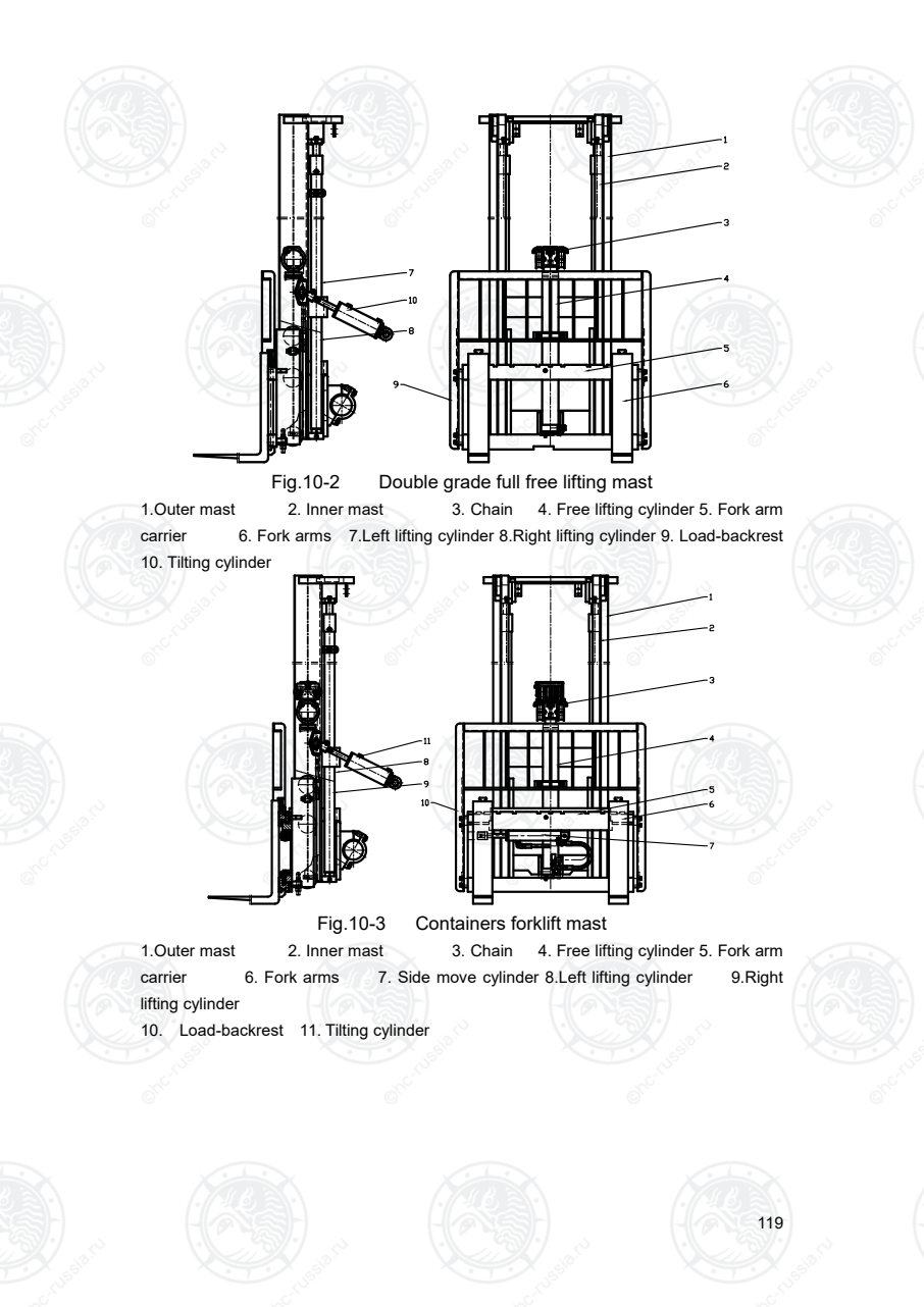
Страница 124
120
Fig.10-4 3 grade full free lifting mast
1.Outer mast 2. Middle mast 3. Inner mast 4. Front cylinder chain 5. Free
lifting cylinder 6. Fork arm carrier 7. Fork arms 8. Chain 9.Left lifting
cylinder
10.Right lifting cylinder 11. Load-backrest 12. Tilting cylinder
Оригинальная страница: таблицы и схемы
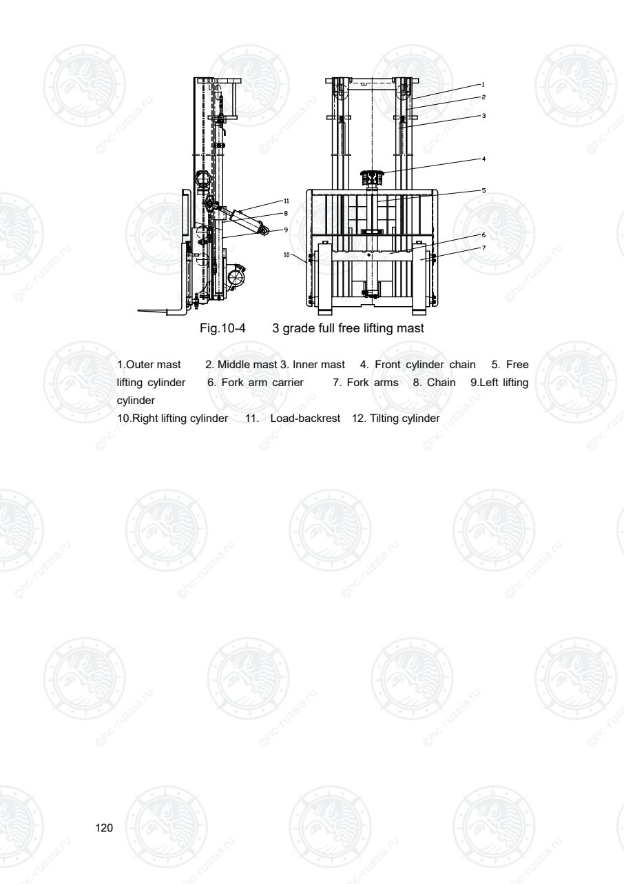
Страница 125
121
Fig.10-5 Lifting cylinder
(Used in fig.10-1, 10-4)
Fig. 10-6 Free lifting cylinder
(Used in fig. 10-2,10-3,10-4)
1. Dustproof
ring
3. Protect ring 3. Gasket ring
1. Dustproof
ring
2. Cylinder
cover
3. Protect ring
4. Guide sleeve 5. O-ring 6. Piston rod 4. Gasket ring 5. O-ring 6. O-ring
7. Cylinder
cover
8. Support ring 9. Protect ring 7. Screw 8. washer 9. Piston rod
10. Gasket
ring
10. Cylinder
cover
11. check
valve
12. Glyd-ring
11. O-ring (Lift cylinder,Right) 13. O-ring
14. Support
ring
15. safety valve
12. safety valve (Lift cylinder,Right)
Оригинальная страница: таблицы и схемы
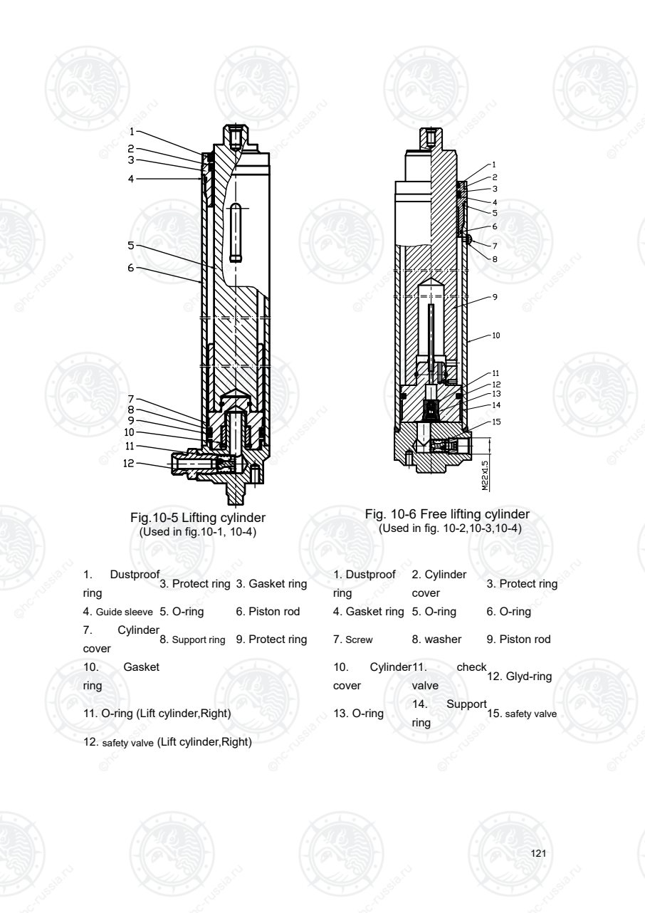
Страница 126
122
Fig.10-7 Lifting cylinder(3.0t-3.8t)
(Used in fig.10-2, 10-3)
Fig.10-8 Lifting cylinder(1.0t-2.5t)
(Used in fig.10-2, 10-3)
1. Dustproof
ring
2. Cylinder cover
3. Protect
ring
1. Dustproof
ring
2. Cylinder
cover
3. Protect ring
4. Gasket ring 5. O-ring
6. Guide
sleeve
4. Gasket ring 5. O-ring 6. plug screw
7. plug screw 8. Piston rod 9. Cylinder 7. Piston rod 8. Cylinder 9. Sleeve
10. Sleeve 11. Support ring 10.Support ring
12. O-ring (Lift cylinder,Right) 11. O-ring (Lift cylinder,Right)
13. safety valve (Lift cylinder,Right) 12. safety valve (Lift cylinder,Right)
Оригинальная страница: таблицы и схемы
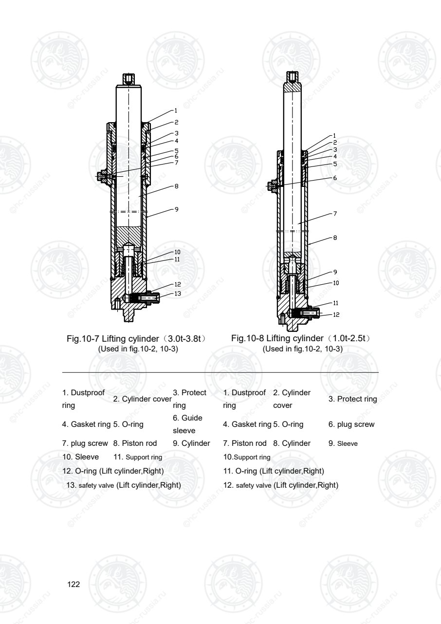
Страница 127
123
4. Removal and adjustment
△! WARNING
Be careful when removing and
installing the forks, carriage and
mast as they are heavy.
4.1 Remove forks and mast
assembly
1) Unlock fork lock pins by pulling
them and move forks to cutout
portion in the middle of carriage
bracket assembly.
2) Pull lower portion of fork to
remove its lower jaw and lift it out.
△! WARNING
a. Keep hands and feet away from
forks when removing and installing
forks carefully, keep feet and hands
clear.
b. Do not remove forks from the
end of the fork bar. Severe injury
can result if the fork is dropped.
1) Attach wire ropes to carriage
bracket assembly and lift carriage
bracket assembly up with a lifting
device.
2) Remove chain attaching nuts,
and detach chains from carriage
bracket assembly.
3) Remove carriage bracket
assembly from inner mast.
4) Detach high pressure hose, lift
hose and low pressure hose.
5) Support mast assembly with
wire ropes.
6) Pull out tilt cylinder pivot pin.
Оригинальная страница: таблицы и схемы
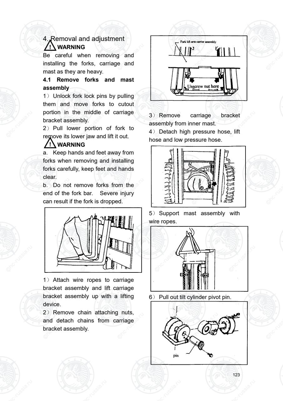
Страница 128
124
7) Remove mast support caps.
8) Remove mast assembly.
9) To install mast assembly,
reverse order of removal.
4.2 Disassembly
△! WARNING
Be careful when disassembling the
masts as they are heavy.
Remove lifting jack
1) Place mast flat on ground.
Remove lifting jack attaching
bolts-bolts and tighten screw.
2) Slide inner mast, then remove
lifting cylinders.
Remove roller
1) Slide inner mast out until rollers
are exposed and remove little rollers
with bearing puller. Can be directly
with the hand (wearing gloves) to
remove the longitudinal roller, adjust
the gasket.
Remove inner mast
Attach wire rope to middle of
inner mast and slide it out with a
lifting device.
INSPECTION
1) Check lift rollers, roller shafts,
and associated parts for wear or
damage.
2) Replace damaged parts as
required.
4.3 Assembly and adjustment
△! WARNING
Be careful when assembling the
masts as they are heavy.
Lift roller
Slide inner mast into outer mast
and securely attach lift rollers.
Оригинальная страница: таблицы и схемы
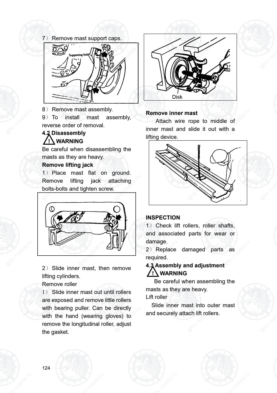
Страница 129
125
Lift roller-to-mast clearance
adjustment
1) Set roller pitch of inner and
outer masts to “L” dimension. Then
proceed with the following
adjustment.
Dimension “L” unit:
mm
Model
or tonnage
Max.lift
height (mm)
Ⅲ
grade
3 t
Ⅱgrade
2t~2.5t
2500~3300 341 306
3600 391 356
4000 441 406
4500 441 406
2) Adjustable range “A” with
shims:
a. Dimension:0.1mm ~
0.6mm.(≤1.8 t)
Dimension:0.1mm~0.6mm (2.0t~
3.8t).
3) It is suitable that clearance of
roller and outer mast is about
0.8mm ~ 1mm. Clearance can’t
adjustable. Replace it if roller wear
too much.
4) Apply lubrication (butter) to
interface of inner mast and outer
mast, interface of roller and mast. To
prevent sand from entering, it is
Оригинальная страница: таблицы и схемы
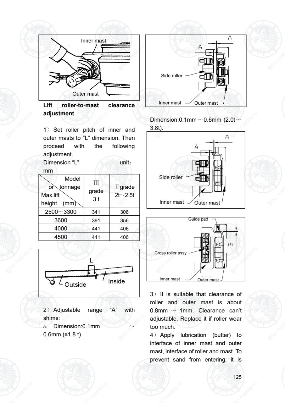
Страница 130
126
decided whether to apply lubrication
or not in the area where sand blown
by wind heavily.
Clearance of back up metal and
mast steel
Adjust clearance “B” to 0.1mm ~
0.8mm with shims, which may not
use. Thickness of shim is 0.5mm or
1mm.
Apply a coat of grease to back-up
metals. Install mast and lifting jack
on forklift truck. Connect circle tube
and high-pressure tube.
4.4 Left and right cylinder height
adjustment.
1) Install left and right lifting jack on
mast, pin must be installed into
orientation hole of outer mast lower
cross beam.
2) Install upper of piston rod on
inner mast. Inner mast lay evenly in
the direction of left, right, upper and
lower. If it is not even, please adjust
by putting washer between hole of
cylinder support and upper end of
piston rod.
3) Installs U-bolt onto cylinder,
hand-tighten nuts and lock it with
two tighten nuts. Screws down
tighten bolt and nuts to avoiding
loosing.
4.5 Lifting chain adjustment
Installs fork arm carrier on inner
mast, and install lifting chain, then
install two nuts on end of every side.
With mast set straight up, lower
carriage completely. Temporarily
adjust clearance of carriage to
74mm-76mm above ground. If
necessary, adjust with chain
adjusting nut.
To adjust tension of lift chain, lower
lifting jack until fork is on the
ground ,and adjust chain adjusting
nut (three every side) so that
dimension C will be as listed below
when the middle portion of chain is
pressed by a finger.
Dimension C: 25mm~30 mm
Оригинальная страница: таблицы и схемы
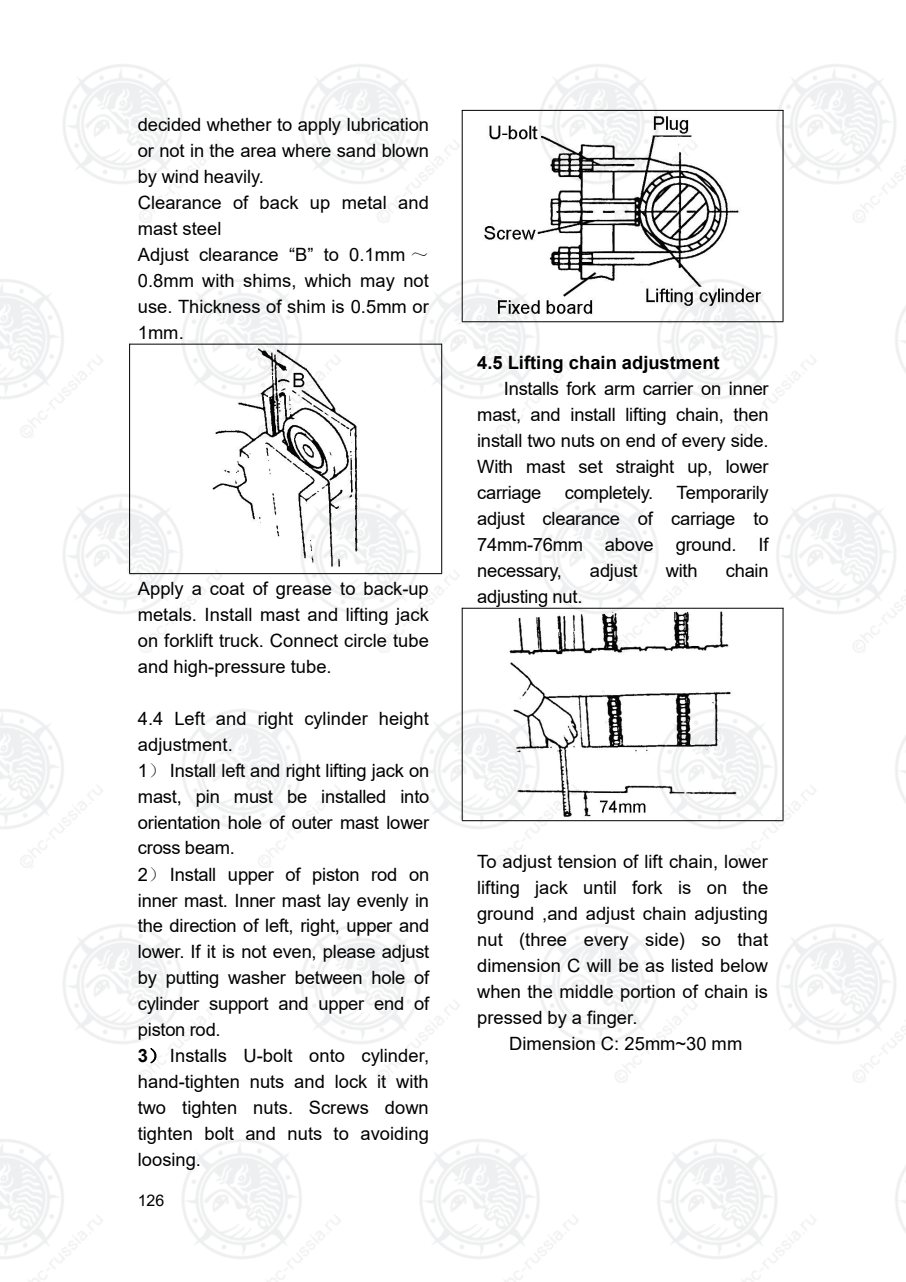
Страница 131
127
4.6 Clearance of fork arm carrier
assembly and rollers adjustment
1)Measure the distance A between
the two channels of the inner mast.
Collect the value on the top, central
part, central beam of the inner
mast(cross) and the bottom
respectively. Mark Aˊ=A-7
1) 2)Measure the space from left
and right side B、Bˊ、B" of rollers
on fork carriage, composite rolling
slider and lift roller respectively.
2) 3)Calculate the difference
values between A and B, A and Bˊ,
A and B" respectively. Each
difference value is the clearance
between the roller and inner mast
channel.
3) Evenly adjust the washers of
each side roller, composite roller
and lift roller on left and right. Adjust
the clearance to the following
range.
A-B= 0.1mm~0.8mm
A-Bˊ= 0.8mm~1.5mm
Aˊ-B"= 0.1mm~0.8 mm
Shims
0.5 mm 1 mm
a. Number of shims must be the
same on the right and left sides,
when using shims.
b. After clearance adjustment, push
carriage assembly to see if it
operates properly.
5. Disassembly and
installation of lifting jack
△! WARNING
Keep body away from equipment
1) Turn out engine, then make
lifting jack falling into lowest
condition that lower of piton rod is
touched bottom of cylinder body
so as to oil flowing back tank
Оригинальная страница: таблицы и схемы
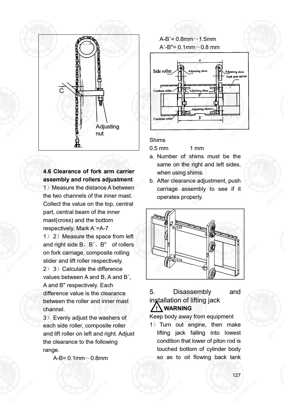
Страница 132
128
completely.
2) Unscrew piston rod and bolt.
3) Disconnect circle oil pipe,
remove high pressure tubes.
4) Remove U-bolt of outer mast
fixation board and tighten skew
of other side.
5) Remove chain of outer mast.
6) Attach wire rope to inner mast and
remove left and right lifting jack with
a lifting device.
5.1 Disassembly
Rated capacity is less than 2.5 t
Remove cylinder head and
guiding bush
Rated capacity is more than 3 t
Removes tighten skew and
nylon stopper, then remove cylinder
head.
1) Remove dust gasket ring.
2) Remove Y-ring with
screwdriver.
CAUTION : Please not use dust
gasket ring removed, O-ring,
Y-ring again, must replace.
3) Draw out piston rod , remove
Y-ring on end of piston.
5.2 Install and replace faulty
parts.
1) Cleanup parts with clean oil
before installation.
2) Then cleanup guiding bush and
piston with hydraulic pressure oil
the same as oil box trademark.
3) Dust or dunghill doesn’t drop
into lifting jack.
4) The order of installation is
reverse the order of
disassembly.
5) Install Y-ring on piston.
6) Install piston rod assembly into
clean cylinder body.
Оригинальная страница: таблицы и схемы
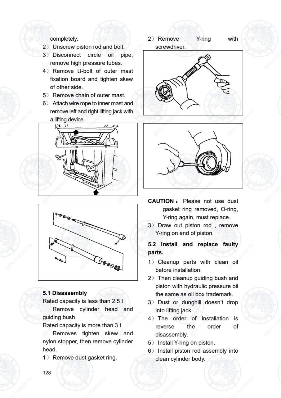
Страница 133
129
CAUTION: The end of cylinder
body mast slick and clean,
installation must set center,
avoid scratching Y-ring.
7) Install replacing dust gasket
ring and Y-ring in guiding bush
and cylinder head.
NOTICE:Apply hydraulic pressure
grease which trademark is the
same as tank on guide sleeve
installed gasket ring
8) Rip cylinder head into piston
rod, screw down cylinder body.
6 . Disassembly and
installation of tilting cylinder
△! WARNING
Noticing proceedings when
removing cylinders.
·Attach wire rope to outer mast,
avoiding mast fall down after
removing tilting cylinder.
·Keep body away from equipment,
no standing under the fork arm
carrier.
1) Lay down fork arm carrier
completely.
2) Remove bolt on the left and
right bracket of outer mast,
moreover pull axis out.
3) Remove oil pipe to the inlet of
tilting cylinder.
4) Remove bolt on the bracket of
Chassis, and pull pin out, then
move tilting cylinder.
5) The order of installation is
reverse the order of disassembly.
6.1 Disassembly of parts
1) Squeeze tilting cylinder with
pliers, then pull piston rod
come-and-go as opening of inlet
and outlet on the tilting cylinder, so
remaining oil is discharged tilting
cylinder.
2) Screw earring bolts 2 loosely,
and screw earring 1 out.
3) Remove cylinder head guiding
bush 3;
4) Draw out piston rod assembly 4
(see as follows).
Оригинальная страница: таблицы и схемы
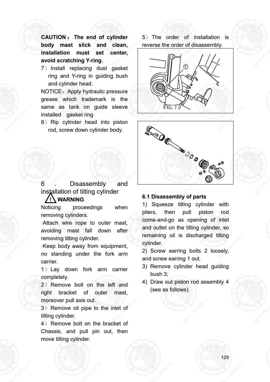
Страница 134
130
5) Remove all dust gasket rings,
O-ring and Y-ring.
6) Remove dust gasket ring in the
cylinder head. Means is the same
as discharging of dust gasket ring in
the cylinder head of lifting jack (see
disassembly and installation of
lifting jack).
7) Remove O-ring outside in the
guiding bush.
8) Remove O-ring and Y-ring in the
inner hole of guiding bush (see Fig.
disassembly and installation of
lifting jack).
CAUTION: No using dust gasket
ring and Y-ring removed.
6.2 Install tilting cylinder after
replacing ring
The order of installation is reverse
to the order of disassembly, but
should notice follow proceedings:
1) Lubricate parts with clean
hydraulic pressure oil.
2) Avoid dust and oil dirty dropping
into tilting cylinder.
3) Avoid scratching the end of
cylinder body, and inlet and outlet
for oil.
4) Push piston rod to cylinder body
when setting center, especially
avoid scratching Y-ring.
5) Before installing guiding bush,
wipe hydraulic pressure oil backing
boardched with employment oil
trademark in the middle of O-ring
and Y-ring in the inner hole of
guiding bush.
6) Don’t scratch O-ring outside in
the guiding bush when installing.
7) Remember install nylon stopper
and tighten screw after screw
cylinder head.
7. Noticing proceeding of
debugging
1) Adjust Forward and BackWard
of the mast
Place fork lift truck on the level
ground, operate control lever to
realize that mast inclined forward or
backWard extremely. As assembly
debugging data required, adjust
combined screw thread length till
according with data of BackWard.
Then lock earring ring close.(please
see foregoing table if you want
know tightening torque of M10 bolt)
2) Adjust installation position of
left and right lifting jack again
Оригинальная страница: таблицы и схемы
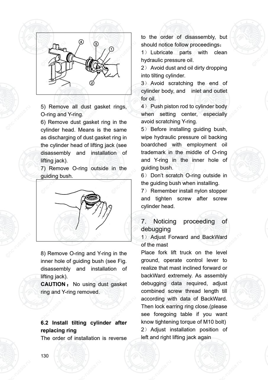
Страница 135
131
a. Adjust washer in the middle of
piston rod and inner mast bracket if
one lifting jack is not
synchronization with the others
when rising or falling, and if one
lifting jack is different height from
the others.
b. Loose two nuts on the U-bolt.
Mast is not rise and lower until
relative position of U-bolt and lifting
jack is suitable. Then screw down
nuts and tightening screw on the
U-bolt. Thus lifting jack can be used
longer and wear of piston rod can
be reduced.
3) Please see foregoing table if
you want know tightening force of
bolt or screw. Please refer to
common bolt tightening torque
prescribed in our company if you
want know other tightening force of
bolt or screw.(refer to OPERATION
AND MAINTAIN MANUAL backing
boardched with it).
Оригинальная страница: таблицы и схемы
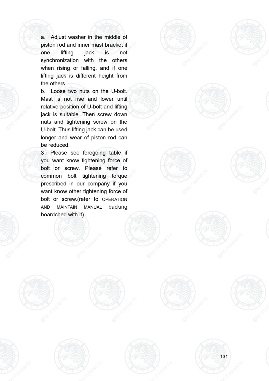
Страница 136
132
Ⅻ.Electrical system
△! WARNING:
Before starting to work on any parts of electrical system, remove rings and
jewelry to prevent an accidental short circuit, and turn off ignition switch and
then disconnect battery ground cable.
DESCRIPTION
Cables are covered with color-coded vinyl for easy identification. In the wiring
diagram, colors are indicated by one or two alphabetical letters.
It is recommended that the battery be disconnected before performing any
electrical service.
CABLE COLORS
Cable colors are indicated by one or two alphabetical letters:
B: black, BR: brown, G: green, L: blue, LG: Light green, R: red, W: white, Y:
yellow, S: gray, P: purple
The main cable is generally coded with a single color. The others are coded
with a two-tone color as below: B/W Black with white stripe G/Y: Green
with yellow stripe
INSPECTION
Inspect all electrical circuit, referring to wiring diagrams. Circuits should be
tested for continuity or short circuit with a conventional test lamp or circuit
tester. Before inspecting circuit, ensure that:
1. Each electrical component part or cable is securely fastened to its
connector or terminal.
2. Each connection is firmly in place and free from rust and dirt.
3. No cable covering shows any evidence of cracks, deterioration or other
damage.
4. Each terminal is a safe distance away from any adjacent mental parts.
5. Each cable is fastened to its proper connector or terminal.
6. Wiring is kept away from any adjacent parts with sharp edges.
7. Wiring is kept away from any rotating or moving parts.
8. Cables between fixed portions and moving parts are long enough to
withstand shocks and vibrations.
9. The wiring keeps a safety distance with the high temperature thing such
as the vent-pipe.
Control box
Component removal
1. Turn key switch "OFF";
2. Press lock buckle on control box and open the cover;
3. Remove fuse and relay from box.
Оригинальная страница: таблицы и схемы
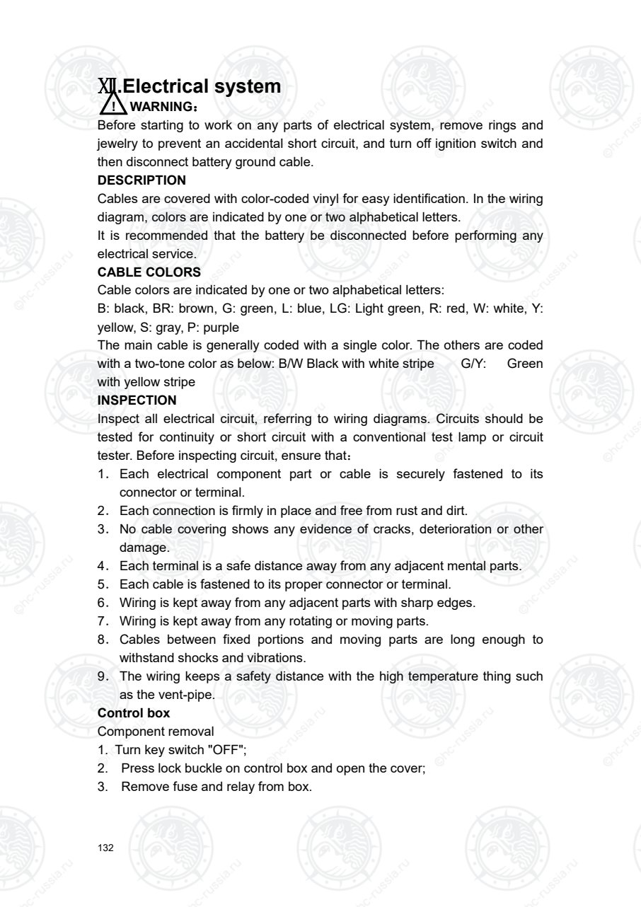
Страница 137
133
INSPECTION:
If fuse is broken, replace with new one. Refer to figure as follow:
(Specific see a forklift control box inner)
a. If fuse is blown, be sure to eliminate cause of problem before installing
new fuses.
b. Never use fuse higher than specified rating.
Fusible links
A melting fusible links can be watched or touched easily, if it is not uncertain of
melting, use multimeter or lamp to test.
Note :
1 If fusible links is melted, maybe because of short circuit(current is too high).
No matter which reason, please check and eliminate fault.
②Fusible links can cause heat, do not enlace with adhesive tape . do not put
fusible near other rubber or wiring assembly.
Lighting System
Bulb Specifications
Lamp W
Headlight 9V-36V, 15W
Small headlight
Steering lamp
Width lamp
LED
12V
Combined back lamp
Brake and width lamp
Steering lamp
Reverse lamp
LED
12V
Combined meter
Floodlight
Caution light
12V-2W
12V-2W
Оригинальная страница: таблицы и схемы
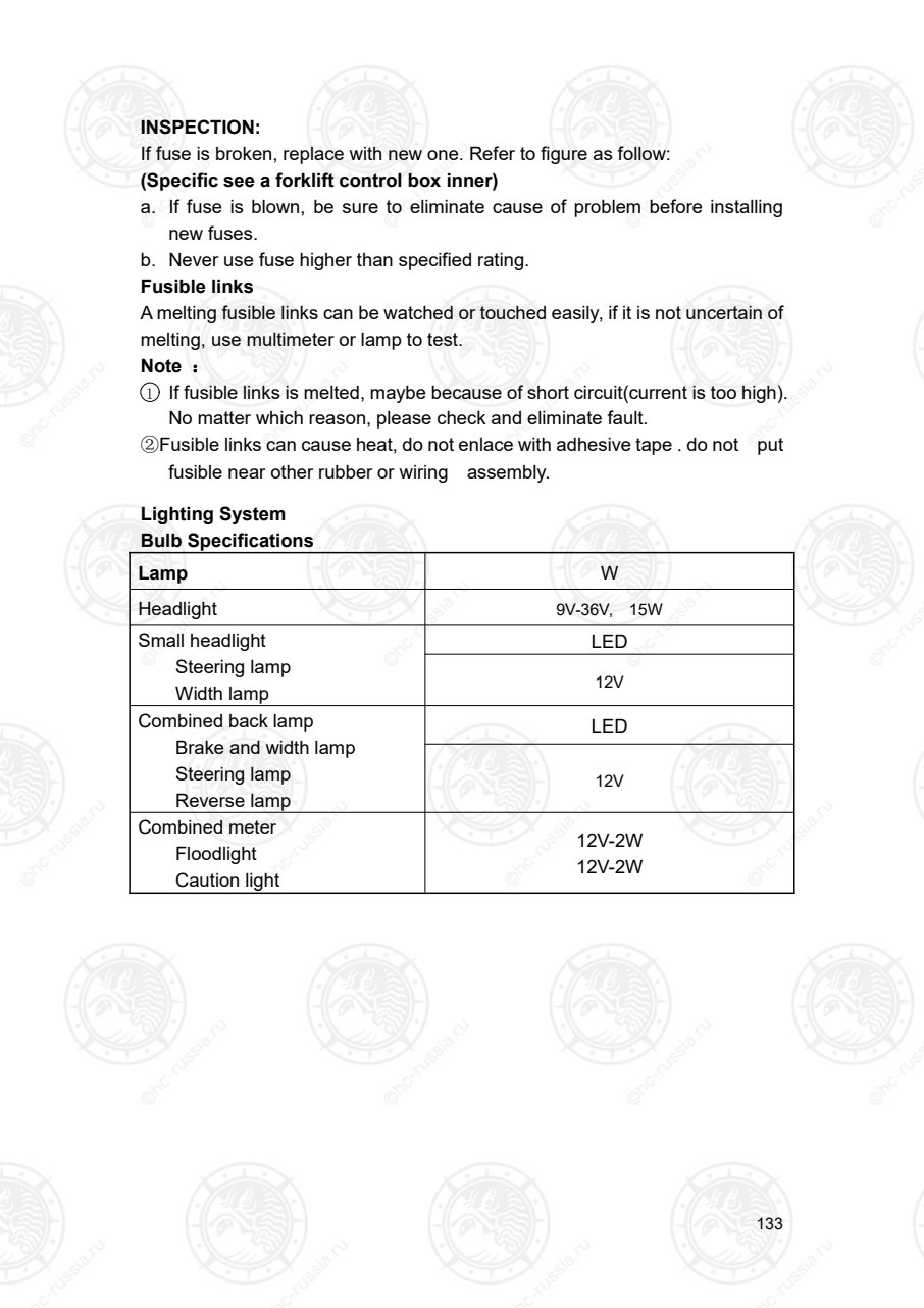
Страница 138
134
Location of light
Front headlight
Disassembly
1.Remove securing nuts of the big-little lamp.
2.Take apart the wiring connector.
3. Remove bolt、lens, then replace faulty
LED with new one.
4. Assembly is the opposite procedures.
Front combination lamp
Disassembly and assembly
Оригинальная страница: таблицы и схемы
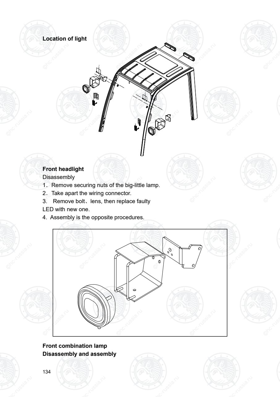
Страница 139
135
1.Remove fixing bolt of bracket.
2.Disconnect the wiring connector.
3.Remove bolt、astigmatism glass, then replace faulty LED with new one.
4. Assembly is the opposite procedures.
REAR COMBINATION LAMP
1.Remove fixing bolt of bracket.
2.Disconnect the wiring connector.
3.Remove bolt、astigmatism glass, then replace faulty bulb with new one.
4. Assembly is the opposite procedures.
Combination switch (Electric commutation)
Оригинальная страница: таблицы и схемы
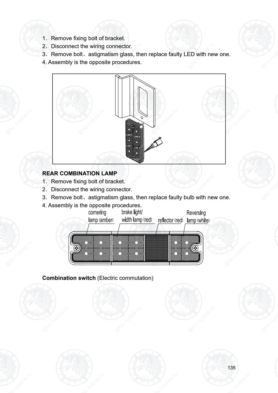
Страница 140
136
Lighting switch and steering switch
Disassembly
1、Remove combination meter;
2、Remove bolt, disconnect wire of inserted and connected part;
3、To install, reverse removal procedures.
Inspect lighting switch
Disconnect switch connector, and check whether each connection point is on.
Use multimeter (with ohm) to inspect whether it is on when lighting switch is on these
positions: headlight, width lamp, OFF.
Switch position Connection point
Оригинальная страница: таблицы и схемы
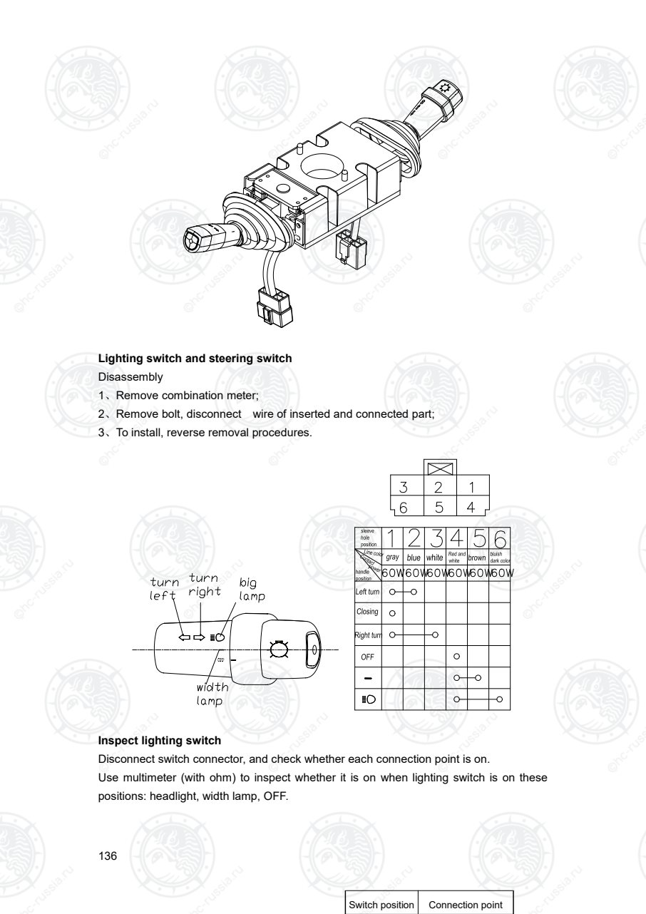
Страница 141
137
Inspect steering lamp
Use multimeter(with ohm) to inspect whether it is on when lighting switch is on these
positions: left turn, N, right turn.
Direction switch
Removal
1、 Remove combination meter;
2、 Screw off bolt, disconnect connector of wring;
3、 To install, reverse removal procedures.
Headlight 4-6
Width lamp 4-5
OFF OFF
Switch
position
Connection point
Left turn 1-2
N OFF
Right left 1-3
Оригинальная страница: таблицы и схемы
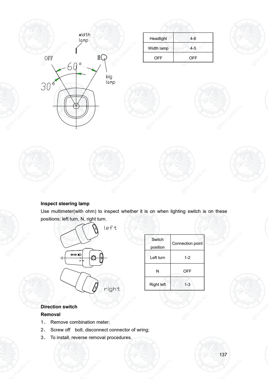
Страница 142
138
Inspect direction switch
Disconnect switch connector, and check whether each connection point is on.
Use multimeter(with ohm) to inspect whether it is on when lighting switch is on these
positions:forward , N, reverse.
Instrument, sensor and relay
Inspect whether relay circuit is on, connect or disconnect coil with proper
Switch position Connection point
Forward 1-3
N OFF
Reverse 2-3
Оригинальная страница: таблицы и схемы
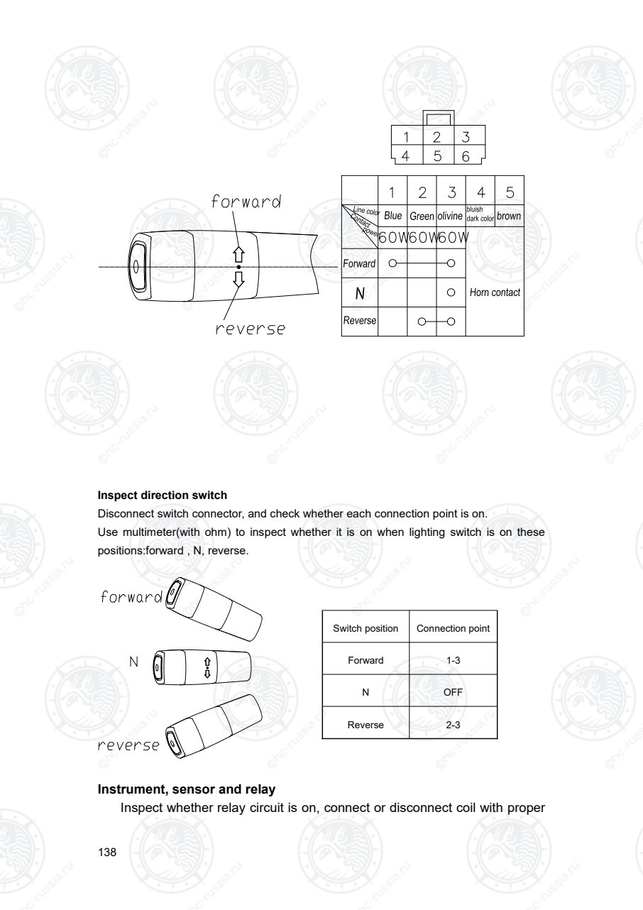
Страница 143
139
voltage(supplied by battery), and then use multimeter(with ohm) to check
whether contactor is on.
Disassembly and installation
Combination meter assembly
1.Remove 4 fixed bolt from meter crust. Notice that when installing and
removing ,please make instrument surface tilt an angle to avoid damaging the
screw thread of fixed parts on truck.
2.Take out wiring harness from sleeve, and then instrument can be brought
out.
3.There is transparent plastic cover to cover, so it can prevent dust and water,
and it is fixed by 6 plastic clip buckle, please press down plastic buckles lightly
to take out plastic cover when removing.
4.To install, reverse removal procedures.
Key (start) switch
1、Remove combination meter.
2、Disconnect connector of wring.
3、Remove nuts, washers, spacers and instrument plate.
4、To install, reverse removal procedures.
Adjust ledge of switch to proper length when installing.
Inspect
Use multimeter (with ohm) to check key switch wether it is on at each position.
Оригинальная страница: таблицы и схемы
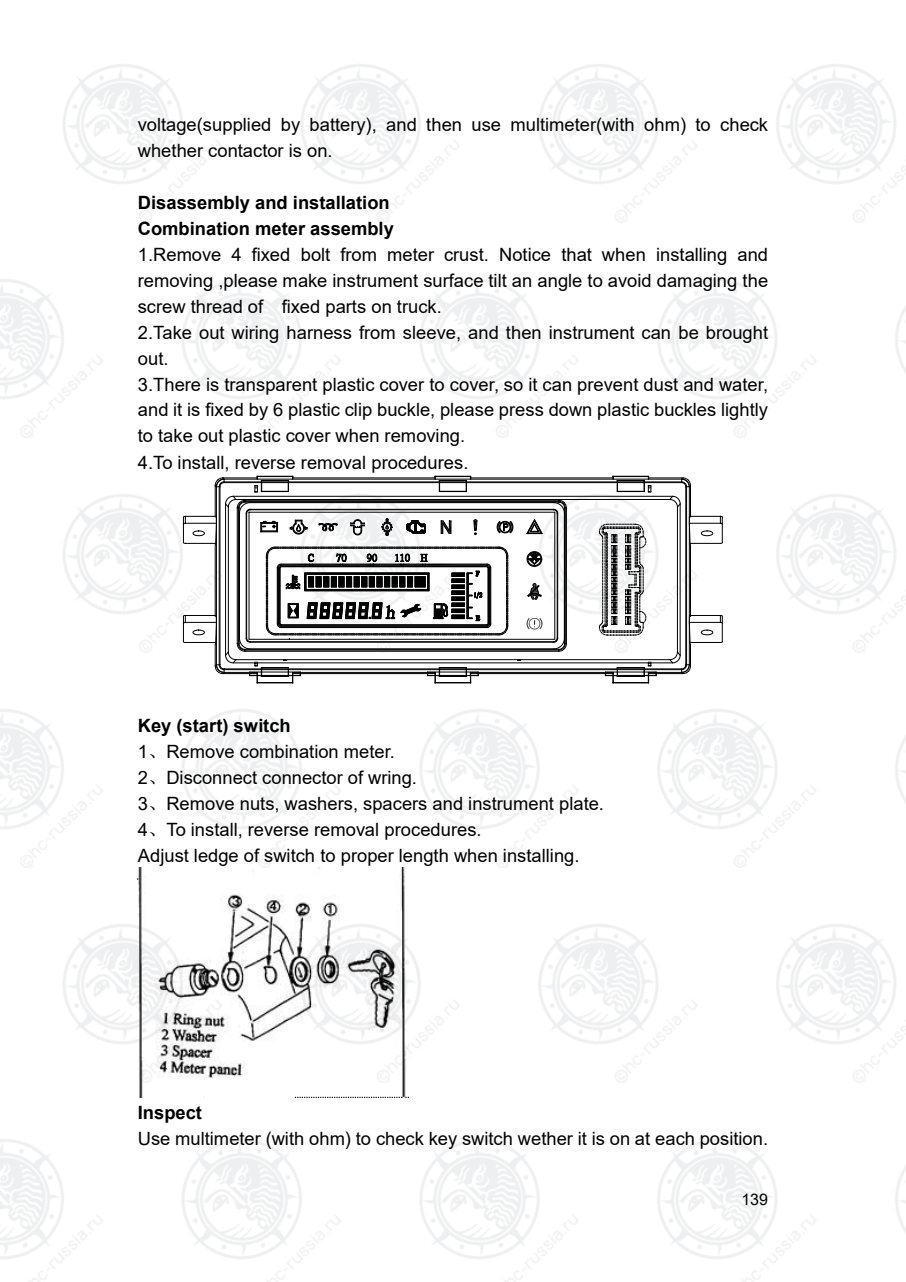
Страница 144
140
Switch position Terminal
OFF OFF
ON B1-B2-Acc on
START B1-B2-Acc-C-R2 on
Principle diagram of preheat start switch
Connection point
Position
B1 B2 Acc C R1 R2
Preheat O O O
Close O O
Run O O O
Start O O O O O
REVERSE BUZZER
1.Remove the wiring terminal , then
unscrew the bolt.
2.To install, reverse removal procedure.
HORN
REMOVAL AND INSTALLATION
1.Disconnect horn harness connector.
2.Remove bolt and horn.
3.To install, reverse removal procedure.
Оригинальная страница: таблицы и схемы
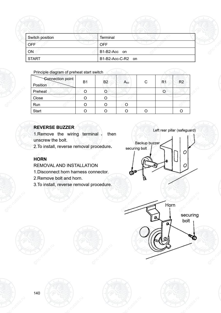
Страница 145
141
Оригинальная страница: таблицы и схемы

Страница 146
142
Fig. 1-1 CPCD15/18/20/25/30/35-XRG71 、CPCD20/25/30/35-XRG72、CPCD20/25/30/35-XRG72F、CPCD15/18-XRG71J、CPCD15/18-XRG71JF
CPCD15/18-XRG91、CPCD20/25/30/35/38-XRG92 Electrical system diagram
Оригинальная страница: таблицы и схемы
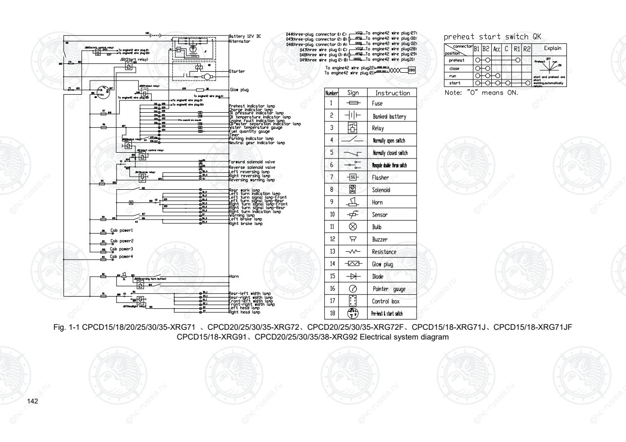
Страница 147
143
Note: "O " m eans O N.
start and preheat are short
working,autom atically
return.
Fig. 1-2 CPC15/18/20/25/30/35-XRG71, CPC20/25/30/35-XRG72, CPC15/18-XRG91, CPC20/25/30/35/38-XRG92 Electrical system diagram
Оригинальная страница: таблицы и схемы
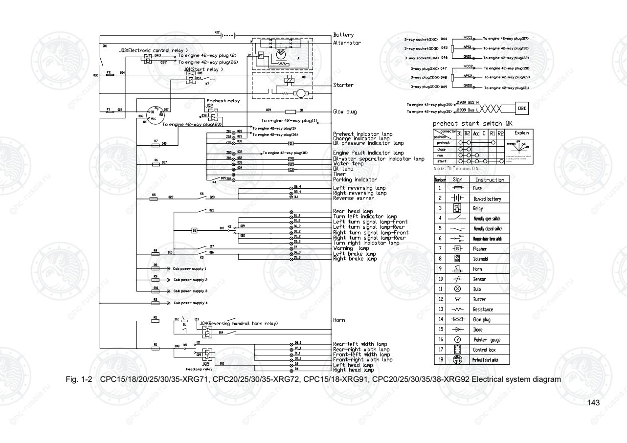
Страница 148
144
Fig. 2 CPCD10/15/18/20/25/30/35-XRW43 、CPCD20/25/30/35-XRW43B、CPCD20/25/30/35-XRW43F Electrical system diagram
Оригинальная страница: таблицы и схемы
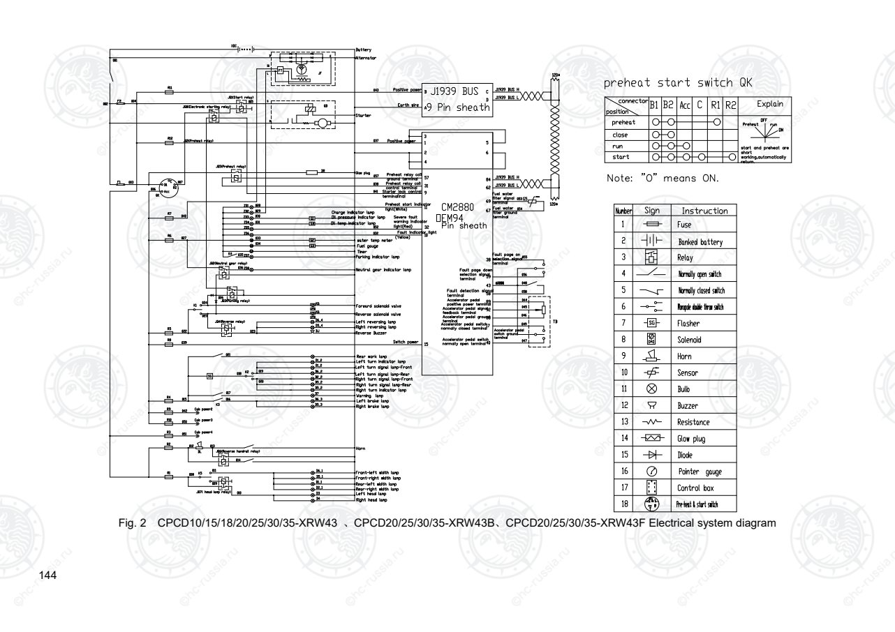
Страница 149
145
Fig.3 W21/W22/W52 engine Electrical system diagram
Оригинальная страница: таблицы и схемы
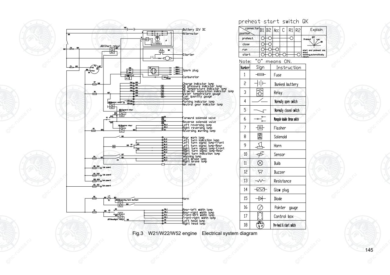
Страница 150
146
Fig. 4 CPCD20/25/30/35-XRW56、CPCD20/25/30/35-XRW56B(B1)、CPCD20/25/30/35-XRW56F Electrical system diagram
Оригинальная страница: таблицы и схемы
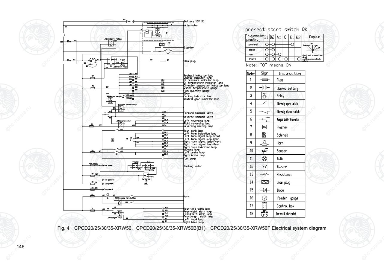
Страница 151
147
Note: "O " m eans O N.
start and preheat are short
working,autom atically
return.
Fig. 5 CPC15/18-XRW10,CPC20/25/30-XRW10 Electrical system diagram
Оригинальная страница: таблицы и схемы
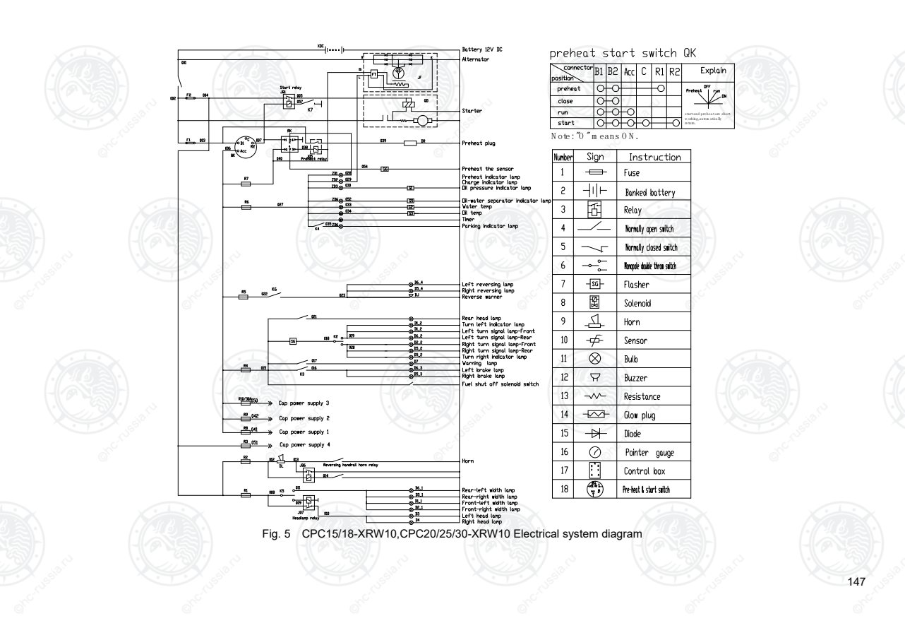
Страница 152
148
Note: "O " m eans O N.
start and preheat are short
working,autom atically
return.
Fig. 6 CPCD15/18-XRW10,CPCD20/25/30-XRW10,CPCD20/25/30-XRW10B(B1),CPCD20/25/30-XRW10F Electrical system diagram
Оригинальная страница: таблицы и схемы
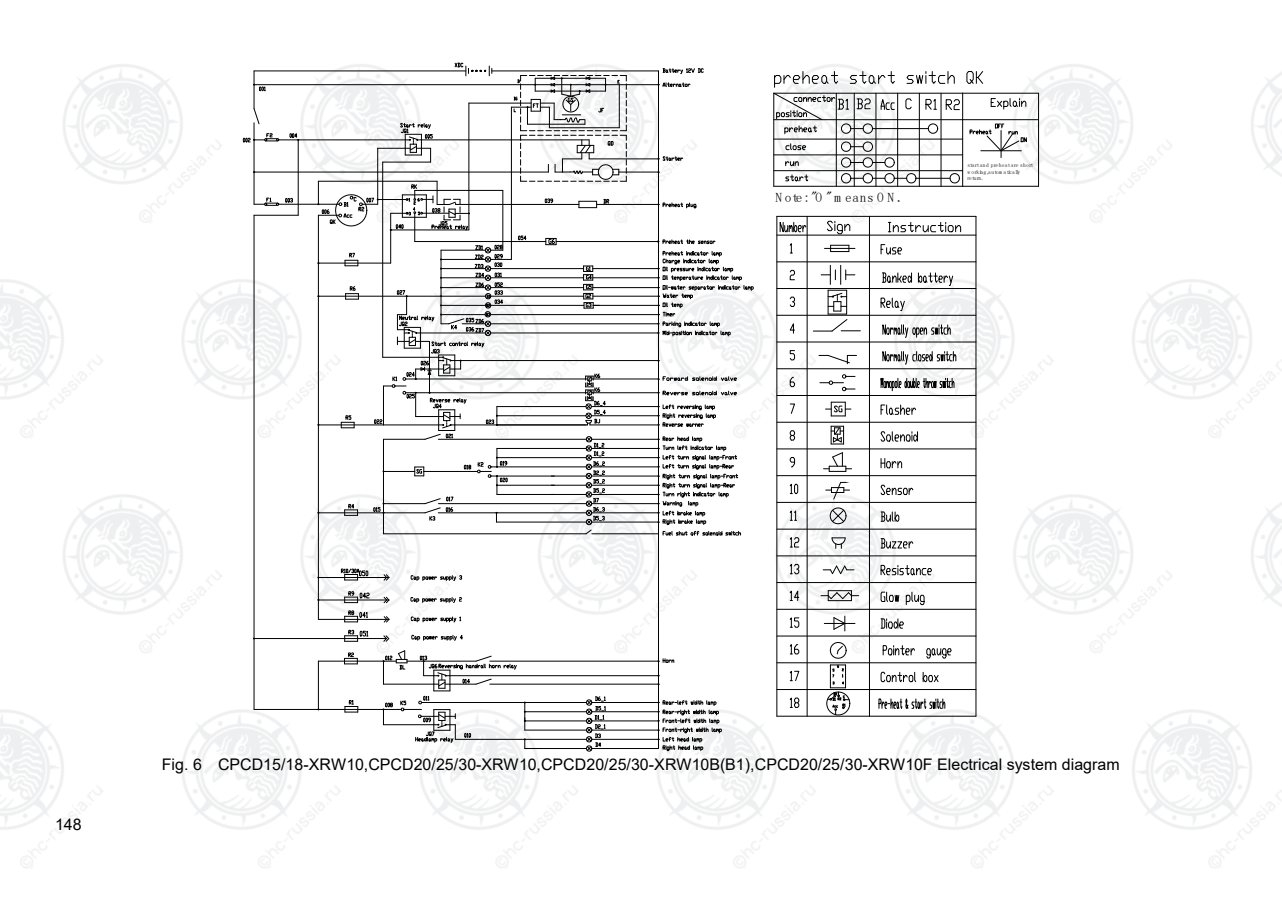
Страница 153
149
start and preheat are short
working,automatically return.
Fig. 7 CPCD15/18-XRW91F,CPCD20/25/30/35/38-XRW92F Electrical system diagram
Оригинальная страница: таблицы и схемы
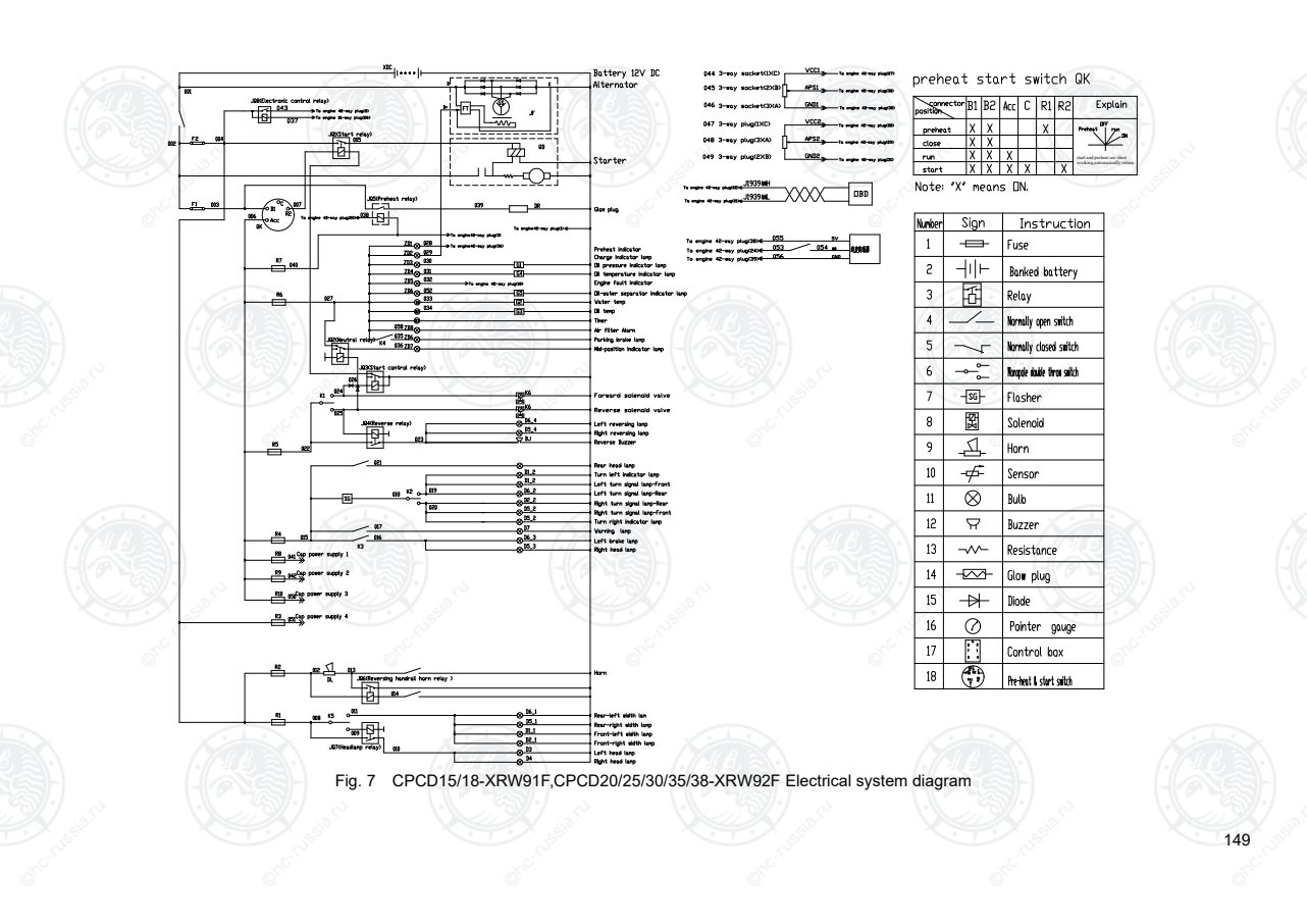
Страница 154
150
start and preheat are short
working,automatically return.
Right headlamp
Left headlamp
Front right side lamp
Left front side lamp
Right rear side lamp
Rear left side marker lamp
Electric horn
Right brake light
Left brake light
Alarm lamp
Right turn indicator
Right rear turn signal
Right front turn signal
Rear left turn signal
Left front turn signal
Left turn indicator
Rear headlight
Reversing warning lamp
Right reverse lamp
Left reverse lamp
Reverse solenoid valve
Forward solenoid valve
Middle indicator
Parking brake indicator
Air filter alarm light
Chronograph
Fuel gauge
Oil water separation warning lamp
Oil temperature warning lamp
Engine fault indicator
Oil pressure warning lamp
Charging indicator
heat ready indicator
Glow plug
Starter
alternator
Battery
Water temperature gauge
Fig. 8 CPCD20/25/30/35-XRG59、CPCD20/25/30/35-XRG60 Electrical system diagram
Оригинальная страница: таблицы и схемы
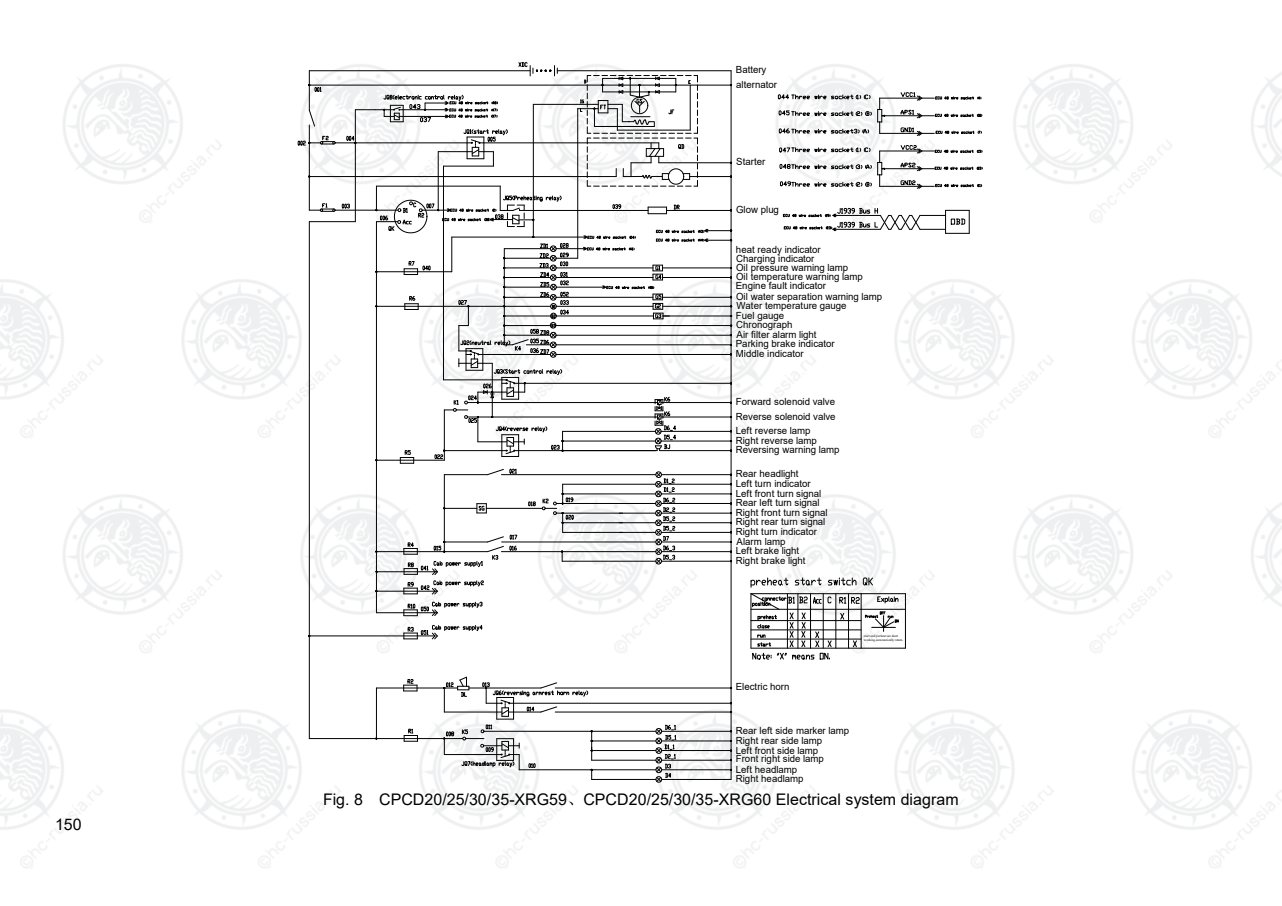
Страница 155
151
Right headlamp
To engine cable plug (21)
To engine cable plug (22)
To engine cable plug (39)
To engine cable plug (24)
To engine cable plug (38)
To engine cable plug (27)
To engine cable plug (30)
To engine cable plug (32)
To engine cable plug (28)
To engine cable plug (31)
To engine cable plug (29)
start and preheat are short
working,automatically return.
Left headlamp
Front right side lamp
Left front side lamp
Right rear side lamp
Rear left side marker lamp
Electric horn
Right brake light
Left brake light
Alarm lamp
Right turn indicator
Right rear turn signal
Right front turn signal
Rear left turn signal
Left front turn signal
Left turn indicator
Rear headlight
Reversing warning lamp
Right reverse lamp
Left reverse lamp
Reverse solenoid valve
Forward solenoid valve
Middle indicator
Parking brake indicator
Air filter alarm light
Chronograph
Fuel gauge
Oil water separation warning lamp
Oil temperature warning lamp
Engine fault indicator
Oil pressure warning lamp
Charging indicator
heat ready indicator
Glow plug
Starter
alternator
Battery
To engine cable plug (1)
To engine cable plug (3)
To engine cable plug (36)
To engine cable plug (18)
To engine cable plug (2)
To engine cable plug (26)
To engine cable plug (20)
Fig. 9 CPCD15/18-XRG98、CPCD15/18-XRG98F、CPCD20/25/30/35/38-XRG92F Electrical system diagram
Оригинальная страница: таблицы и схемы
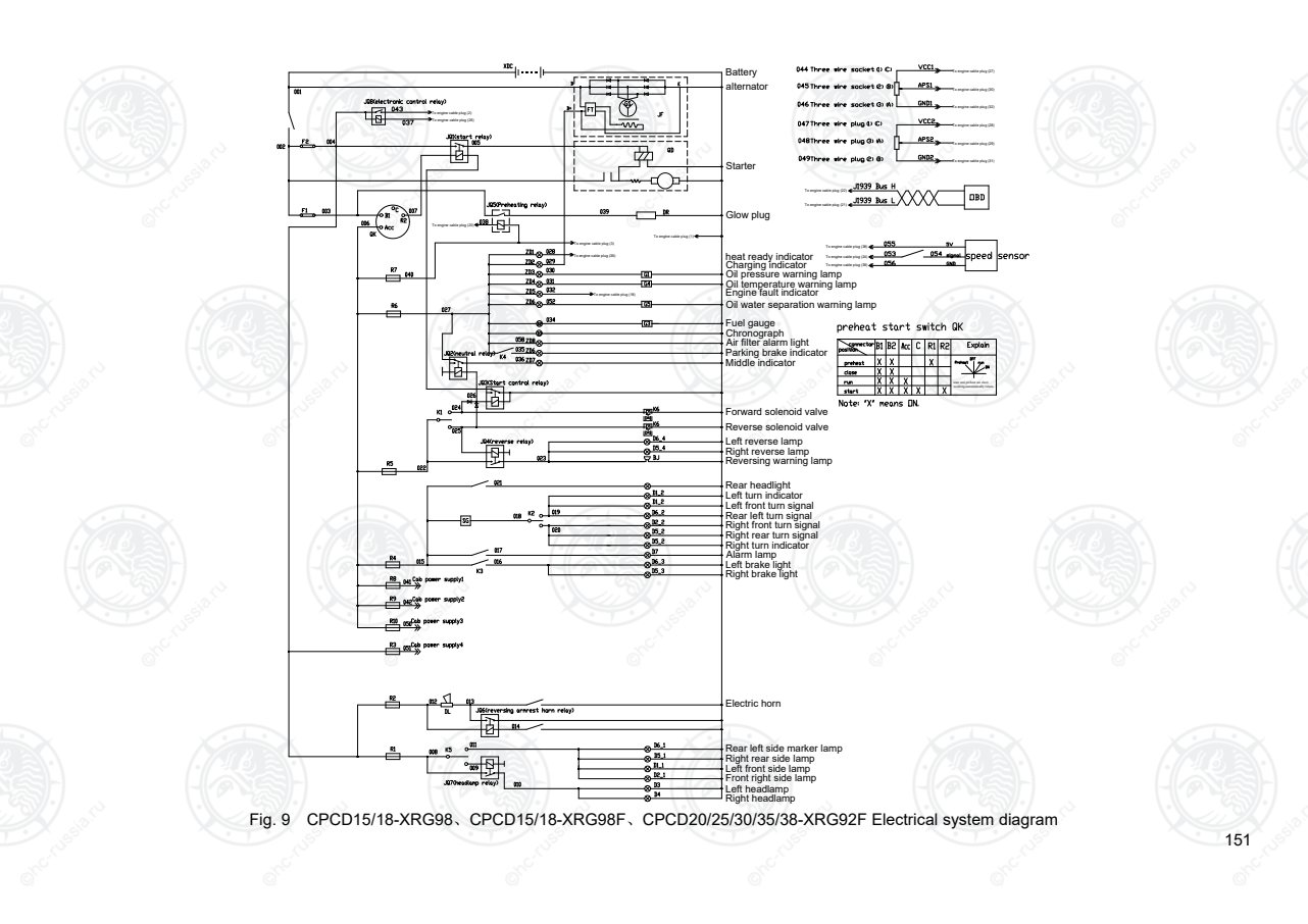
Страница 156
152
N ote: "O " m eans O N .
start and preheat are short
w orking,autom atically
return.
Fig. 10 CPCD20/25/30/35/38-XRG2 Electrical system diagram
Оригинальная страница: таблицы и схемы
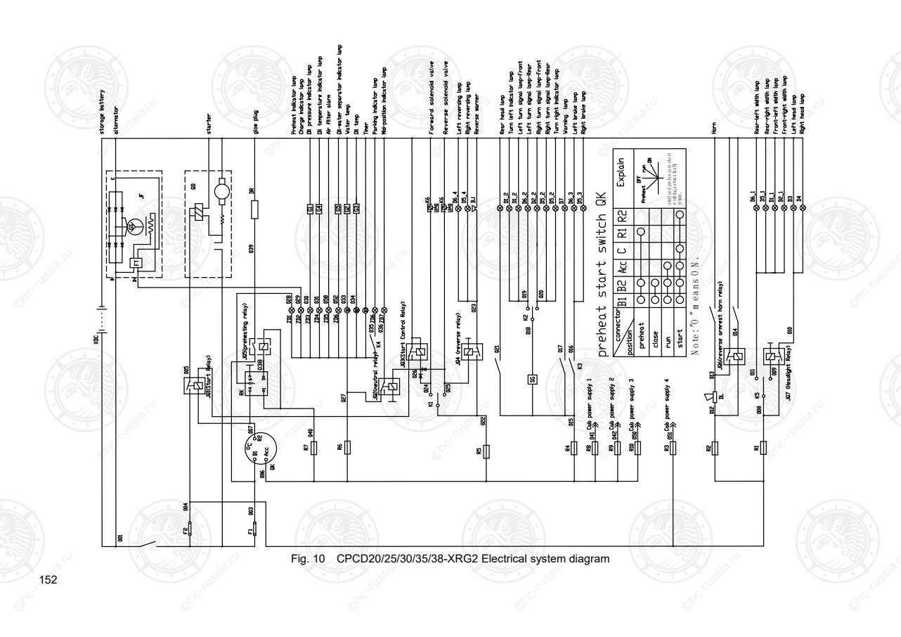
Страница 157
153
Fig. 11 CPYD20/25/30/35/38-XRW52F、CPYD20/25/30/35/38-XRW52B(B1) Electrical system diagram
Оригинальная страница: таблицы и схемы
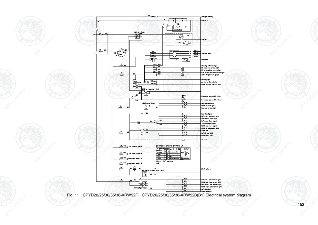
Страница 158
154
Preheat
Run
Start
OFF
Contact
Position
Fig. 12 CPCD15/18-XRW32F、CPCD15/18-XRW32B、CPCD15/18-XRW32B1、CPCD20/25/30/35-XRW33、CPCD20/25/30/35-XRW33B、CPCD20/25/30/35-XRW33F
Electrical system diagram(No OPS forklift truck)
Оригинальная страница: таблицы и схемы
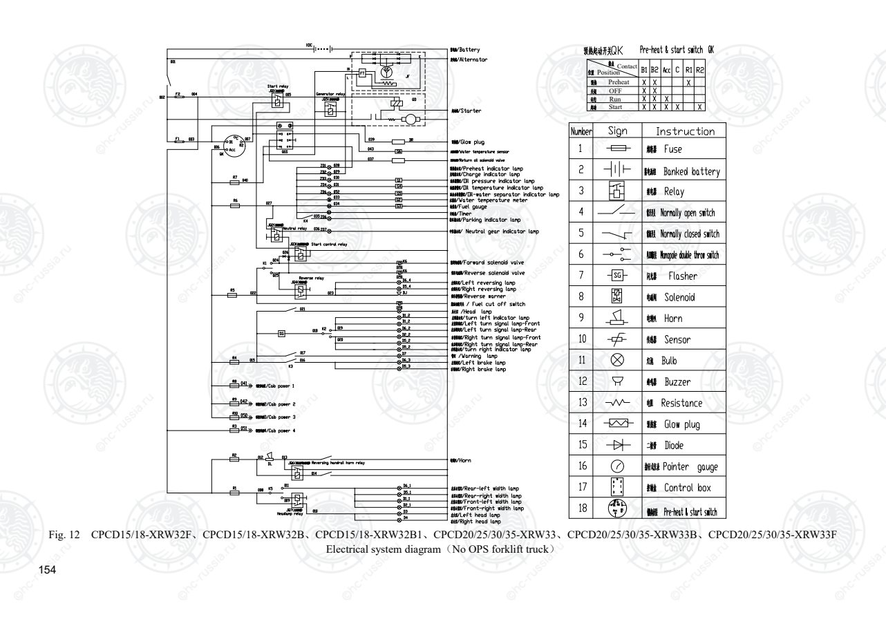
Страница 159
155
Battery 12V DC
Alternator
Starter
Glow plug
Water temperature sensor
Oil return solenoid valve
Preheat indicator lamp
Charge indicator lamp
Oil pressure indicator lamp
Oil temperature indicator lamp
Oil-water separator indicator lamp
Water temperature gauge
Oil gauge
Timer
Air filter warning light
Parking indicator
Neutral indicator
Fault indication
Left reversing lamp
Right reversing lamp
Reverse warner
Turn right indicator lamp
Left turn signal lamp-Front
Left turn signal lamp-Rear
Right turn signal lamp-Front
Right turn signal lamp-Rear
Turn right indicator lamp
Warning  lamp
Left brake lamp
Right brake lamp
Rear-left width lamp
Rear-right width lamp
Front-left width lamp
Front-right width lamp
Left head lamp
Right head lamp
Parking brake
indicator
Mid-position
indicator
Seat belt
indicator
Fault
indicator
High and low
speed switch
signal
Seat signal
Seat belt
indicator
Hand brake signal
Forward gear
Reverse gear
Buzzer
Starter signal
Forward solenoid
valve output
High and low speed switch
output
Multiple unit valve
Reverse solenoid valve
output
Controller Gnd
Cab power supply 1
Cab power supply 2
Cab power supply 3
Cab power supply 4
Seat belt indicator
Motion control valve
Lowering control valve
Forward solenoid valve
Reverse solenoid valve
Buzzer
Rear head lamp
Horn
Fig. 13 CPCD15/18-XRW32F、CPCD15/18-XRW32B、CPCD15/18-XRW32B1、CPCD20/25/30/35-XRW33、CPCD20/25/30/35-XRW33B、CPCD20/25/30/35-XRW33F
Electrical system diagram(OPS forklift truck)
Оригинальная страница: таблицы и схемы
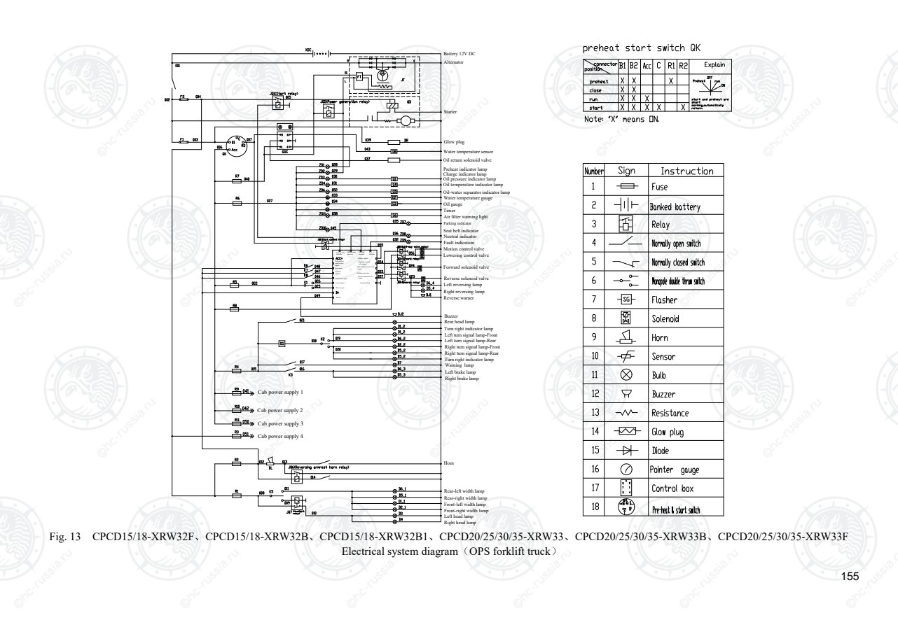
Страница 160
HANGCHA GROUP CO. , LTD.
■ Address For: OVERSEAS USERS
■ Address: 666 Xiangfu Road, Lin'an,Hangzhou, Zhejiang, China
■ Fax: 0086-571-88926789 0086-571-88132890 ■ ZIP:311305
■ Web: http://www.hcforklift.com ■ E-mail: sales@hcforklift.com
Оригинальная страница: таблицы и схемы
Уточните документ по серийному номеру
Если исполнение машины отличается от указанного в руководстве, передайте фото её заводской таблички в сервис.