

Hangcha X 4,0–5,0 т: Service Manual 2025
Сервисный PDF на английском для тяжёлой части серии X: устройство и обслуживание погрузчиков с ДВС 4,0–5,0 т.
- Модели и серия
- X series Internal Combustion Counterbalanced Forklift Truck 4.0t–X5.0t
- Язык документа
- Английский
- Назначение документа
- Сервисное руководство · 07/2025
Для какой техники этот документ
В документе описаны X series Internal Combustion Counterbalanced Forklift Truck 4.0t–X5.0t. Полный индекс на заводской табличке должен соответствовать перечню руководства. Для вашей машины используйте документацию нужной редакции и комплектации. Редакция руководства: 07/2025.
Читать полную инструкциюДокумент целиком
Скачать PDF Полный текст инструкции
Страница 1
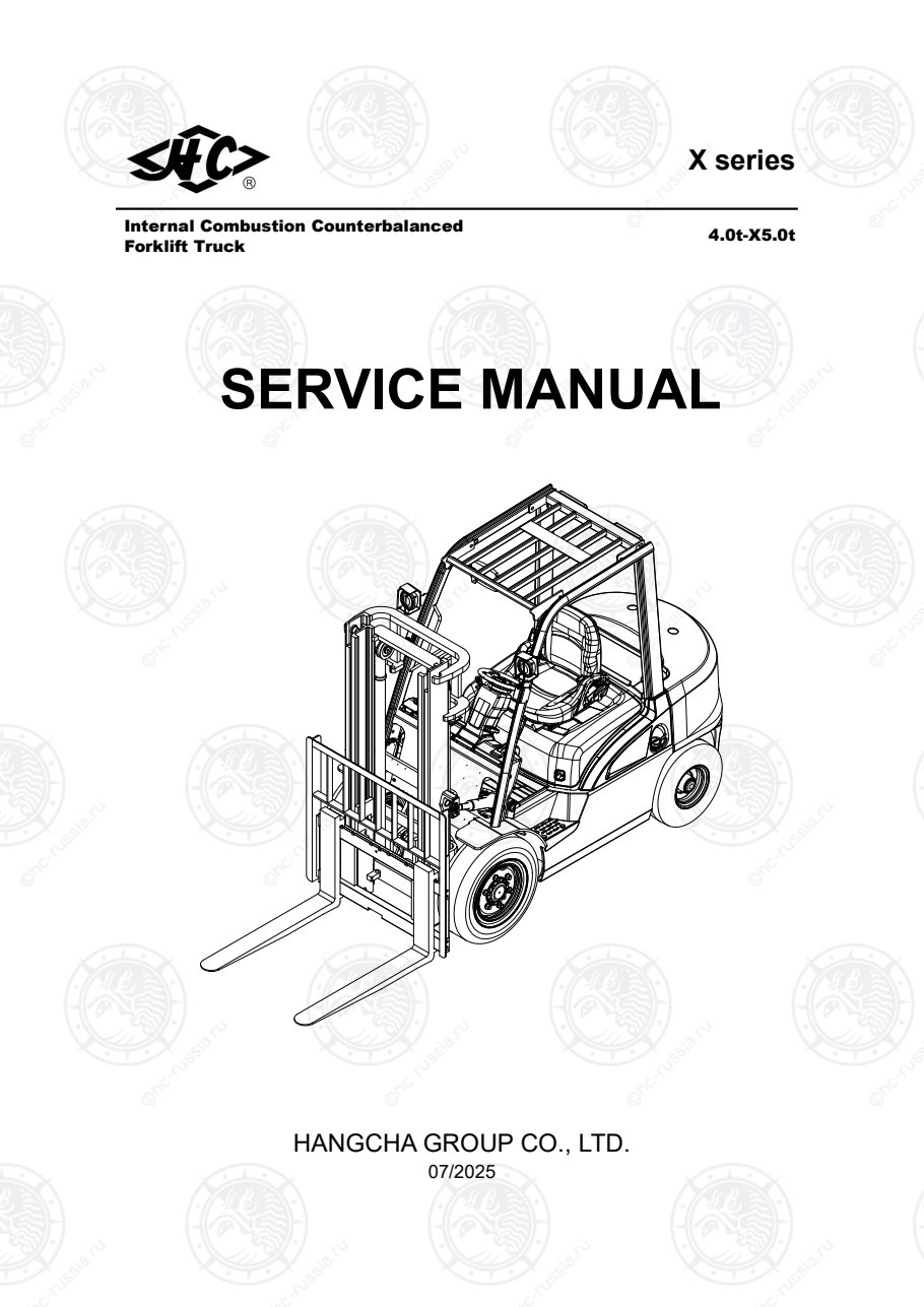
SERVICE MANUAL
HANGCHA GROUP CO., LTD.
07/2025
X series
Internal Combustion Counterbalanced
Forklift Truck 4.0t-X5.0t
Оригинальная страница: таблицы и схемы
Страница 2
HANGCHA GROUP CO. , LTD.
■ Address For: OVERSEAS USERS
■ Address: 88 Donghuan Road, LinAn Economic Development Zone,
Hangzhou, P.R. of China ■ ZIP:311305
■ Fax: 0086-571-88926789 0086-571-88132890
■ Web: http://www.hcforklift.com
■ E-mail: sales@hcforklift.com
Оригинальная страница: таблицы и схемы
Страница 3
Foreword
Thank you very much for buying Hangzhou forklift.
4t-5t X series internal combustion forklift is our company’s new product which is
developed recently with using the newest appearance design method. The truck with smooth
line and innervation comes up to the latest international appearance trends.
The optimized operate system with advanced man-machine engineering technology and
the advanced technique of damping in our trucks make our trucks more comfortable to
operate.
This manual instructs you the structure, principle and servicing methods on internal
combustion forklift.
This manual also applies to container forklift truck and forklift truck assembled
attachments.
Our product design will update and perform better, so the content in this manual may be
not the same as the forklift you owned.
It is forbidden anybody without training and qualification to maintain.
Only in the event that the truck manufacturer is no longer in business and there is no
successor in the interest to the business, the user may arrange for a modification or alteration
to a powered industrial truck provided, however, that the user shall:
a) Arrange for the modification or alteration to be designed, tested and implemented by
an engineer(s) expert in industrial trucks and their safety;
b) Maintain a permanent record of the design, test(s) and implementation of the
modification or alteration;
c) Approve and make appropriate changes to the capacity plate(s), decals, tags and
instruction handbook;
d)Affix a permanent and readily visible label to the truck stating the manner in which the
truck has been modified or altered together with the date of the modification or alteration,
and the name and address of theorganisation that accomplished the tasks.
© 07/2025 HANGCHA GROUP CO., LTD.
Оригинальная страница: таблицы и схемы
Страница 4
CONTENT
Ⅰ. Power System ...................................................................................................................... 1
1.Engine for Forklift............................................................................................................ 1
2.Chinese IV exhaust system with tail gas treatment:.......................................................7
3.Exhaust after treatment device(only for Chinese IV).................................................8
Ⅱ.Drive system ........................................................................................................................10
1.Summarize .....................................................................................................................10
2.Hydrodynamic power transmission gear-box ............................................................... 12
3.Mechanical gearbox ...................................................................................................... 24
3.Driving axle .................................................................................................................... 29
Ⅲ Steering system ...................................................................................................................42
1.Structure introduction .................................................................................................... 42
2.Technical parameters .................................................................................................... 45
3.Steering system installation notes ................................................................................ 45
4.Fault diagnoses and corrections ................................................................................... 46
5.Hydraulic steering gear................................................................................................. 46
6.Steering axle ..................................................................................................................49
7.Steering cylinder ............................................................................................................51
Ⅳ.Brake system .......................................................................................................................53
1.Summary ........................................................................................................................53
2.Data................................................................................................................................54
3.Brake inching pedal adjustment ....................................................................................56
4.Parking brake adjustment ..............................................................................................57
5.Brake..............................................................................................................................58
6.Vacuum booster(Truck with Chinese engine) ...............................................................60
7.Hydraulic boosted braking assembly(Imported engine type).................................. 61
8.Fault diagnoses and corrections ................................................................................... 67
9.Brake schematic ............................................................................................................ 68
Ⅴ.Hydraulic system .................................................................................................................69
1.Data................................................................................................................................69
2.Trouble diagnoses and corrections ...............................................................................70
3.Main pump..................................................................................................................... 72
4.Multi-pathway valve .......................................................................................................73
5.Hydraulic system circuit .................................................................................................75
Ⅵ. Lifting system ..................................................................................................................... 78
1.Summary ........................................................................................................................78
2.Assemble debugging data .............................................................................................79
3.Trouble diagnoses and corrections ...............................................................................81
4.Removal and adjustment ...............................................................................................84
5.Disassembly and installation of lifting jack....................................................................88
6.Disassembly and installation of tilting cylinder............................................................. 90
7.Noticing proceeding of debugging ................................................................................ 91
Оригинальная страница: таблицы и схемы
Страница 5
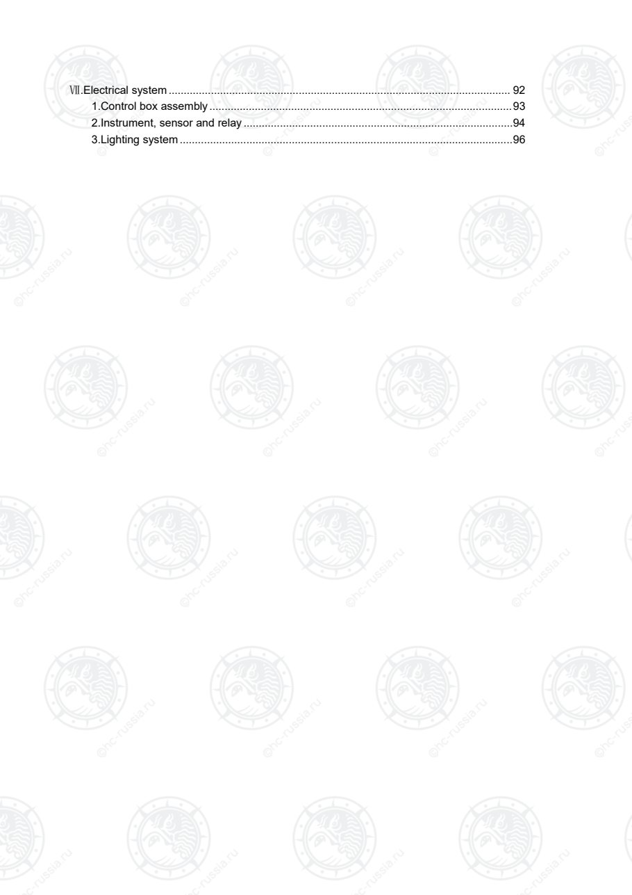
Ⅶ.Electrical system ................................................................................................................. 92
1.Control box assembly ....................................................................................................93
2.Instrument, sensor and relay .........................................................................................94
3.Lighting system ..............................................................................................................96
Оригинальная страница: таблицы и схемы
Страница 6
1
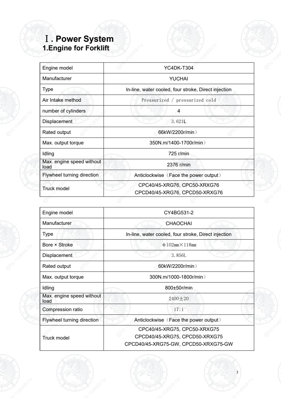
Ⅰ. Power System
1.Engine for Forklift
Engine model YC4DK-T304
Manufacturer YUCHAI
Type In-line, water cooled, four stroke, Direct injection
Air Intake method Pressurized / pressurized cold
number of cylinders 4
Displacement 3.621L
Rated output 66kW/2200r/min)
Max. output torque 350N.m/1400-1700r/min)
Idling 725 r/min
Max. engine speed without
load 2376 r/min
Flywheel turning direction Anticlockwise(Face the power output)
Truck model CPC40/45-XRG76, CPC50-XRXG76
CPCD40/45-XRG76, CPCD50-XRXG76
Engine model CY4BG531-2
Manufacturer CHAOCHAI
Type In-line, water cooled, four stroke, Direct injection
Bore × Stroke φ102mm×118mm
Displacement 3.856L
Rated output 60kW/2200r/min)
Max. output torque 300N.m/1000-1800r/min)
Idling 800±50r/min
Max. engine speed without
load 2400±20
Compression ratio 17:1
Flywheel turning direction Anticlockwise(Face the power output)
Truck model
CPC40/45-XRG75, CPC50-XRXG75
CPCD40/45-XRG75, CPCD50-XRXG75
CPCD40/45-XRG75-GW, CPCD50-XRXG75-GW
Оригинальная страница: таблицы и схемы
Страница 7
2
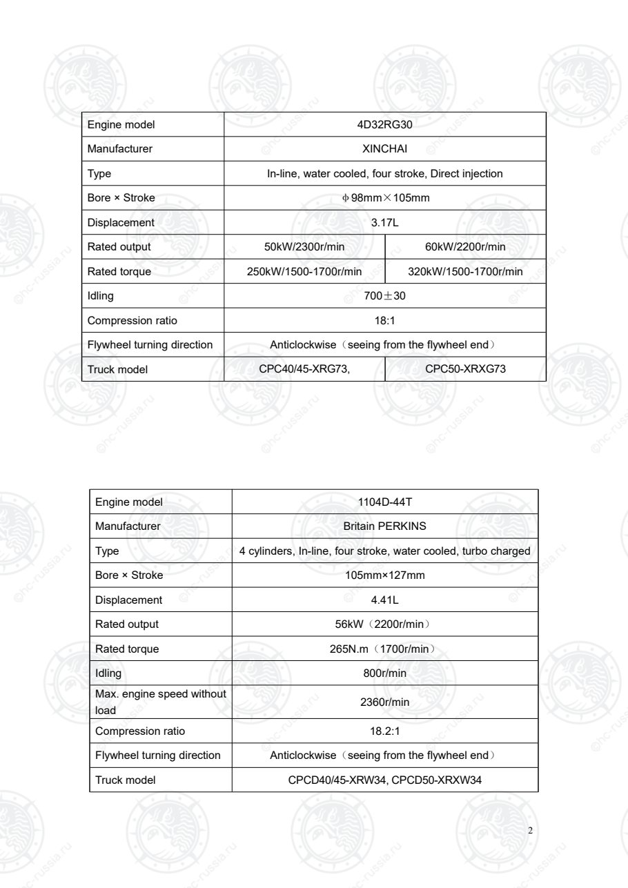
Engine model 4D32RG30
Manufacturer XINCHAI
Type In-line, water cooled, four stroke, Direct injection
Bore × Stroke φ98mm×105mm
Displacement 3.17L
Rated output 50kW/2300r/min 60kW/2200r/min
Rated torque 250kW/1500-1700r/min 320kW/1500-1700r/min
Idling 700±30
Compression ratio 18:1
Flywheel turning direction Anticlockwise(seeing from the flywheel end)
Truck model CPC40/45-XRG73, CPC50-XRXG73
Engine model 1104D-44T
Manufacturer Britain PERKINS
Type 4 cylinders, In-line, four stroke, water cooled, turbo charged
Bore × Stroke 105mm×127mm
Displacement 4.41L
Rated output 56kW(2200r/min)
Rated torque 265N.m(1700r/min)
Idling 800r/min
Max. engine speed without
load 2360r/min
Compression ratio 18.2:1
Flywheel turning direction Anticlockwise(seeing from the flywheel end)
Truck model CPCD40/45-XRW34, CPCD50-XRXW34
Оригинальная страница: таблицы и схемы
Страница 8
3
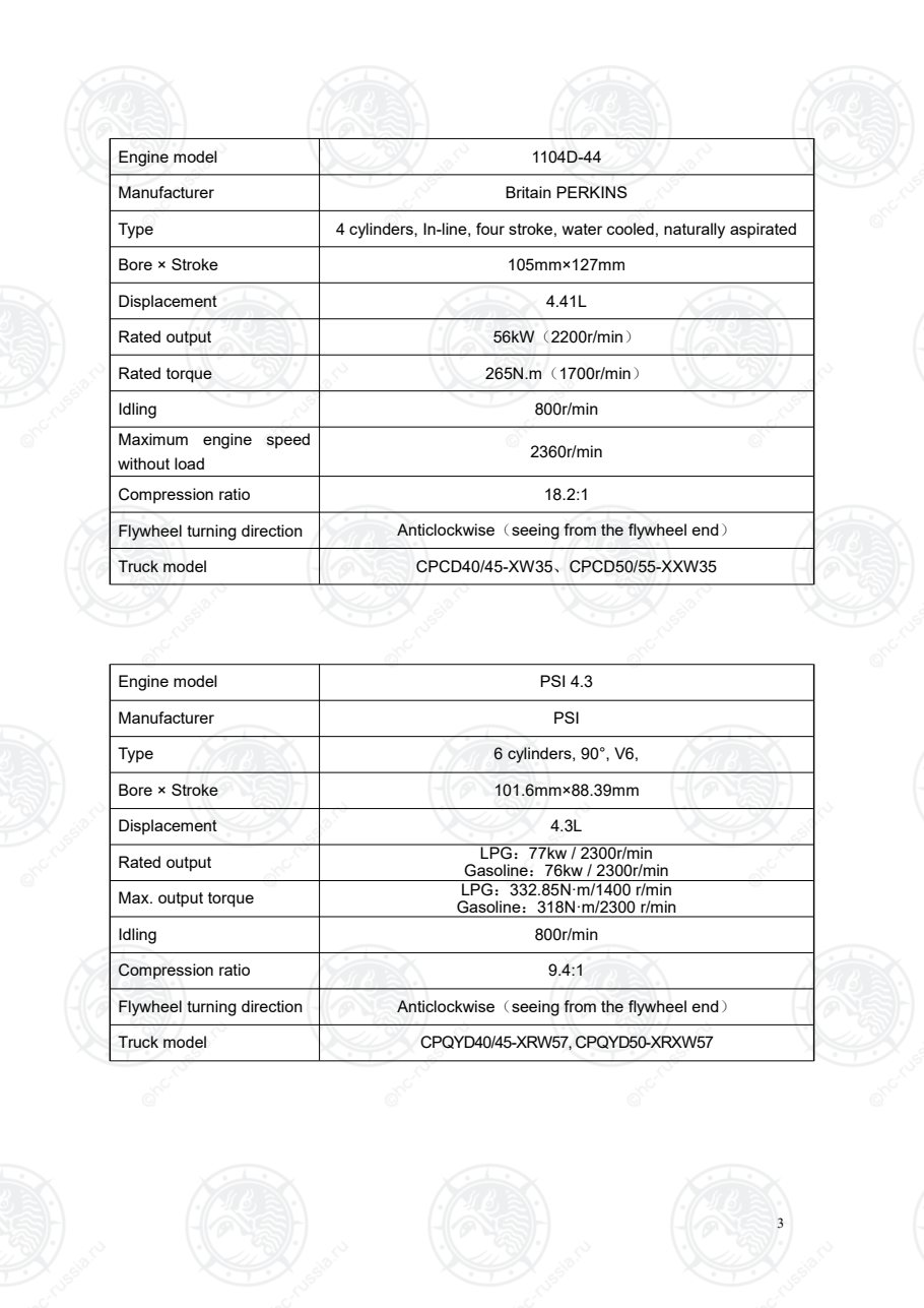
Engine model 1104D-44
Manufacturer Britain PERKINS
Type 4 cylinders, In-line, four stroke, water cooled, naturally aspirated
Bore × Stroke 105mm×127mm
Displacement 4.41L
Rated output 56kW(2200r/min)
Rated torque 265N.m(1700r/min)
Idling 800r/min
Maximum engine speed
without load 2360r/min
Compression ratio 18.2:1
Flywheel turning direction Anticlockwise(seeing from the flywheel end)
Truck model CPCD40/45-XW35、CPCD50/55-XXW35
Engine model PSI 4.3
Manufacturer PSI
Type 6 cylinders, 90°, V6,
Bore × Stroke 101.6mm×88.39mm
Displacement 4.3L
Rated output LPG:77kw / 2300r/min
Gasoline:76kw / 2300r/min
Max. output torque LPG:332.85N·m/1400 r/min
Gasoline:318N·m/2300 r/min
Idling 800r/min
Compression ratio 9.4:1
Flywheel turning direction Anticlockwise(seeing from the flywheel end)
Truck model CPQYD40/45-XRW57, CPQYD50-XRXW57
Оригинальная страница: таблицы и схемы
Страница 9
4
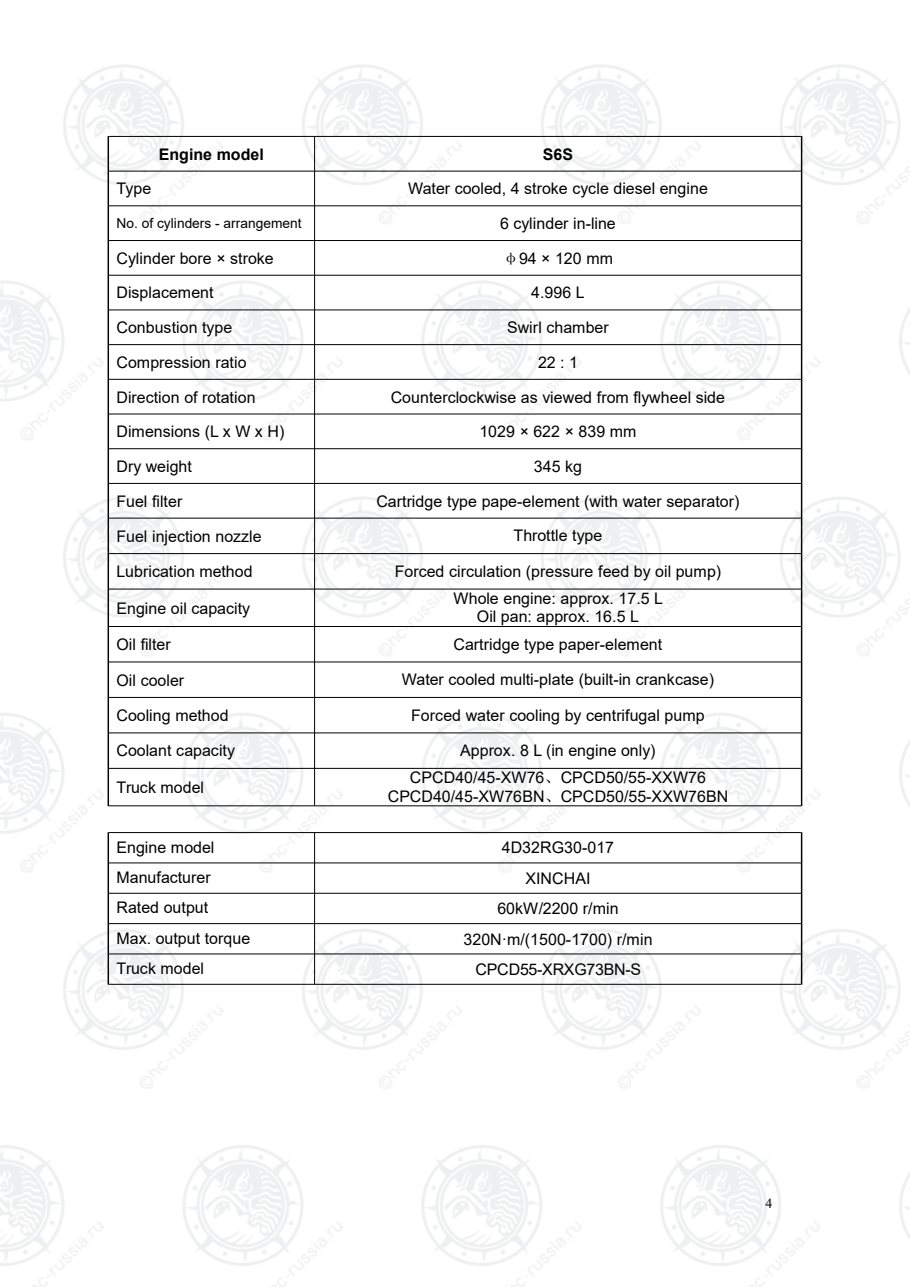
Engine model S6S
Type Water cooled, 4 stroke cycle diesel engine
No. of cylinders - arrangement 6 cylinder in-line
Cylinder bore × stroke φ94 × 120 mm
Displacement 4.996 L
Conbustion type Swirl chamber
Compression ratio 22 : 1
Direction of rotation Counterclockwise as viewed from flywheel side
Dimensions (L x W x H) 1029 × 622 × 839 mm
Dry weight 345 kg
Fuel filter Cartridge type pape-element (with water separator)
Fuel injection nozzle Throttle type
Lubrication method Forced circulation (pressure feed by oil pump)
Engine oil capacity Whole engine: approx. 17.5 L
Oil pan: approx. 16.5 L
Oil filter Cartridge type paper-element
Oil cooler Water cooled multi-plate (built-in crankcase)
Cooling method Forced water cooling by centrifugal pump
Coolant capacity Approx. 8 L (in engine only)
Truck model CPCD40/45-XW76、CPCD50/55-XXW76
CPCD40/45-XW76BN、CPCD50/55-XXW76BN
Engine model 4D32RG30-017
Manufacturer XINCHAI
Rated output 60kW/2200 r/min
Max. output torque 320N·m/(1500-1700) r/min
Truck model CPCD55-XRXG73BN-S
Оригинальная страница: таблицы и схемы
Страница 10
5
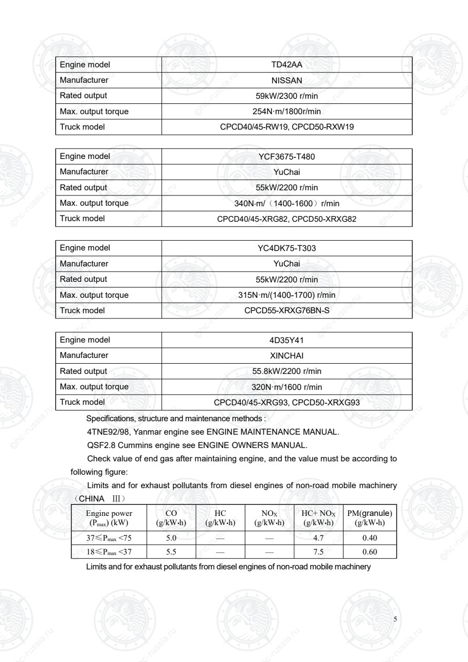
Engine model TD42AA
Manufacturer NISSAN
Rated output 59kW/2300 r/min
Max. output torque 254N·m/1800r/min
Truck model CPCD40/45-RW19, CPCD50-RXW19
Engine model YCF3675-T480
Manufacturer YuChai
Rated output 55kW/2200 r/min
Max. output torque 340Nm/(1400-1600)r/min
Truck model CPCD40/45-XRG82, CPCD50-XRXG82
Engine model YC4DK75-T303
Manufacturer YuChai
Rated output 55kW/2200 r/min
Max. output torque 315N·m/(1400-1700) r/min
Truck model CPCD55-XRXG76BN-S
Engine model 4D35Y41
Manufacturer XINCHAI
Rated output 55.8kW/2200 r/min
Max. output torque 320N·m/1600 r/min
Truck model CPCD40/45-XRG93, CPCD50-XRXG93
Specifications, structure and maintenance methods :
4TNE92/98, Yanmar engine see ENGINE MAINTENANCE MANUAL.
QSF2.8 Cummins engine see ENGINE OWNERS MANUAL.
Check value of end gas after maintaining engine, and the value must be according to
following figure:
Limits and for exhaust pollutants from diesel engines of non-road mobile machinery
(CHINA Ⅲ)
Engine power
(Pmax) (kW)
CO
(g/kW•h)
HC
(g/kW•h)
NOX
(g/kW•h)
HC+ NOX
(g/kW•h)
PM(granule)
(g/kW•h)
37≤Pmax <75 5.0 — — 4.7 0.40
18≤Pmax <37 5.5 — — 7.5 0.60
Limits and for exhaust pollutants from diesel engines of non-road mobile machinery
Оригинальная страница: таблицы и схемы
Страница 11
6
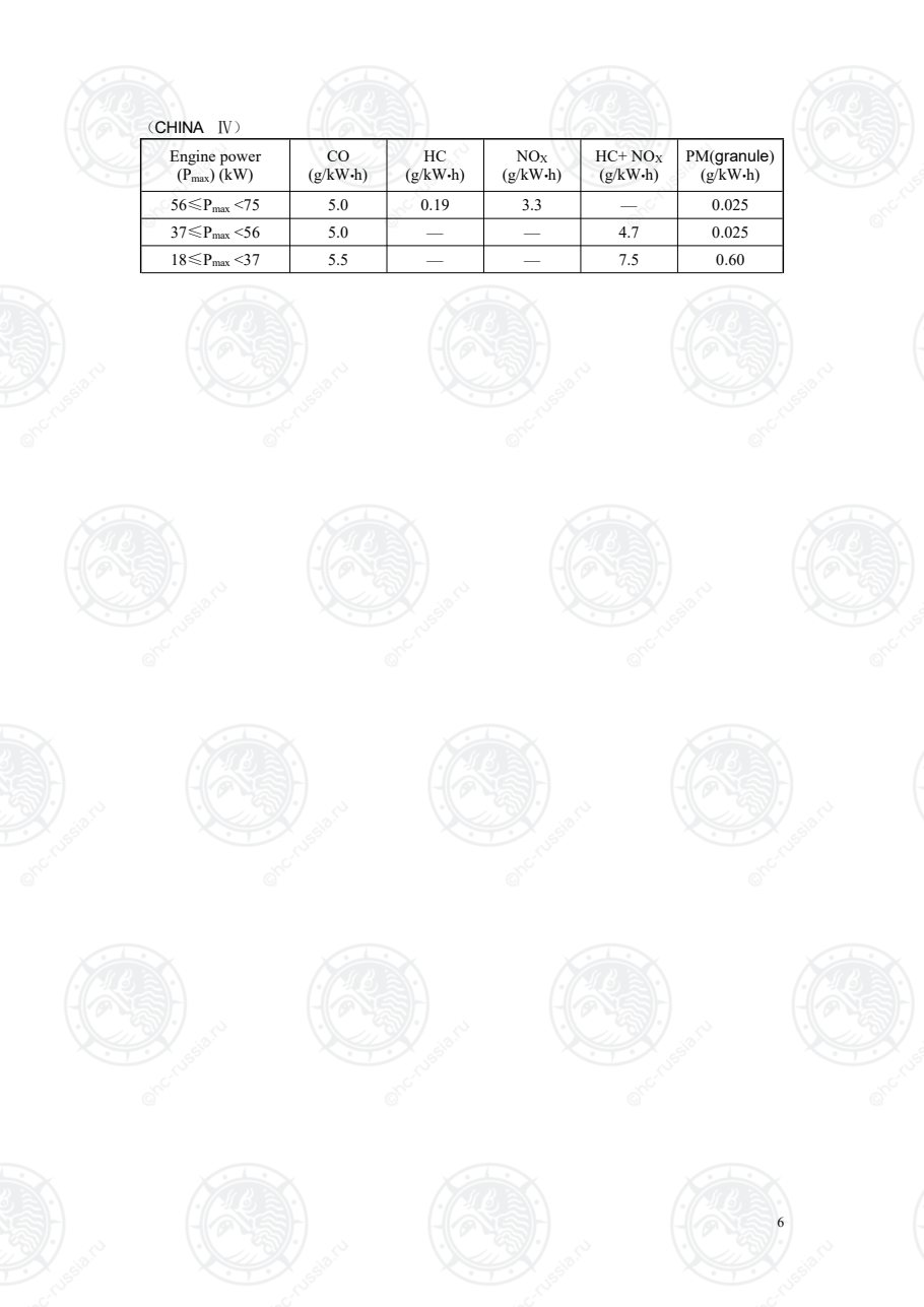
(CHINA Ⅳ)
Engine power
(Pmax) (kW)
CO
(g/kW•h)
HC
(g/kW•h)
NOX
(g/kW•h)
HC+ NOX
(g/kW•h)
PM(granule)
(g/kW•h)
56≤Pmax <75 5.0 0.19 3.3 — 0.025
37≤Pmax <56 5.0 — — 4.7 0.025
18≤Pmax <37 5.5 — — 7.5 0.60
Оригинальная страница: таблицы и схемы
Страница 12
7
2.Chinese IV exhaust system with tail gas treatment:
4
10915
8
6
14
8
7
6
5
12
13
10
11
17
18
19
6 7 16
1
3
2
18
20
T=(45~59)N·mT=(12~15)N·m
T=(22~30)N·m
T=(45~59)N·m
T=(22~30)N·m
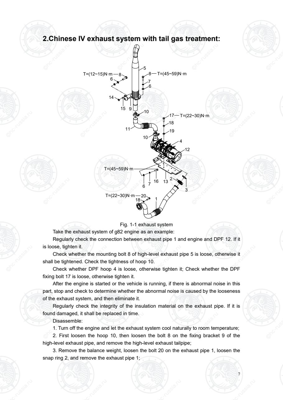
Fig. 1-1 exhaust system
Take the exhaust system of g82 engine as an example:
Regularly check the connection between exhaust pipe 1 and engine and DPF 12. If it
is loose, tighten it.
Check whether the mounting bolt 8 of high-level exhaust pipe 5 is loose, otherwise it
shall be tightened. Check the tightness of hoop 10.
Check whether DPF hoop 4 is loose, otherwise tighten it; Check whether the DPF
fixing bolt 17 is loose, otherwise tighten it.
After the engine is started or the vehicle is running, if there is abnormal noise in this
part, stop and check to determine whether the abnormal noise is caused by the looseness
of the exhaust system, and then eliminate it.
Regularly check the integrity of the insulation material on the exhaust pipe. If it is
found damaged, it shall be replaced in time.
Disassemble:
1. Turn off the engine and let the exhaust system cool naturally to room temperature;
2. First loosen the hoop 10, then loosen the bolt 8 on the fixing bracket 9 of the
high-level exhaust pipe, and remove the high-level exhaust tailpipe;
3. Remove the balance weight, loosen the bolt 20 on the exhaust pipe 1, loosen the
snap ring 2, and remove the exhaust pipe 1;
Оригинальная страница: таблицы и схемы
Страница 13
8
4. Loosen the hoop 10 and remove the exhaust pipe 11;
5. Loosen the sensor connector, loosen the bolt 17 on the DPF support 13, and
remove dpf12 from the DPF support.
The installation process is the reverse of the removal process.
Be careful:
1. After the engine is shut down, the exhaust system still has extremely high
temperature. Please wait for the exhaust system to cool to room temperature before
carrying out relevant maintenance operations to prevent high-temperature scald;
2. Non after sales personnel shall not disassemble the DPF at will; Avoid DPF
damage;
3. There are precision parts inside the DPF. Be careful to collide with the DPF during
disassembly to prevent the DPF from falling.
4. During installation, the tightening torque must meet the requirements of the
drawing.
3. Exhaust after treatment device(only for Chinese IV)
The working principle of exhaust after treatment: during the operation of diesel engine,
exhaust flows through DOC and DPF in turn. The exhaust gas flows through doc, HC and
CO in the exhaust gas are oxidized to CO2 and H2O under the catalysis of oxidation
catalyst to realize the purification of CO and HC, and no in the exhaust gas is oxidized to
NO2 under the catalysis of oxidation catalyst. The exhaust gas flows through the DPF, and
the particles in the exhaust gas are captured and intercepted by the wall flow DPF, so as
to realize the purification of particles. With the increase of particles in the DPF channel,
the exhaust resistance of DPF will increase, which will affect the fuel consumption and
even the normal operation of the engine. In order to avoid this situation, the DPF system
must burn the soot in the intercepted particles, that is regeneration. The NO2 generated by
Doc oxidation can react with the carbon particles in the particles intercepted by DPF
above 250 ℃ to burn off the soot and realize the continuous (passive) regeneration of
DPF. If the vehicle runs at low speed and light load for a long time, the exhaust
temperature is low and the continuous regeneration fails, and the DPF resistance
increases to the set value, the engine will automatically inject diesel in cylinder (or use HC
injector to inject in the exhaust pipe) to increase the temperature of DPF and carry out
active regeneration.
◆DPF cleaning
Since DPF regeneration will leave burning ash, vehicles should regularly go to the
maintenance station to remove the dust accumulated inside DPF unit. If the engine fails,
such as burning oil, causing a complete blockage of DPF, it is also necessary to go to the
service station for maintenance. In both cases, it is necessary to remove the clamps at
both ends of the DPF, remove the DPF, and use special equipment to remove more than
90% of the ash or carbon deposit.
If XINCHAI diesel engine has an alarm or every 4000 operating hours, the DPF
needs to be cleaned.
If YUCHAI engine has alarm or works every 2000 ~ 3000 hours, it needs to clean
DPF once.
Оригинальная страница: таблицы и схемы
Страница 14
9
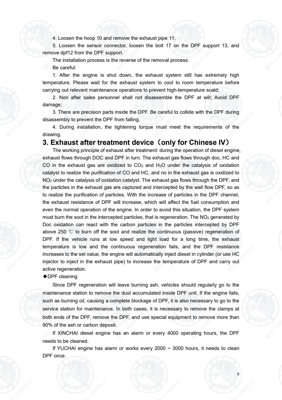
For this service or agency, please contact the sales company or agent of HangCha
Group Co., Ltd.
Оригинальная страница: таблицы и схемы
Страница 15
10
Ⅱ.Drive system
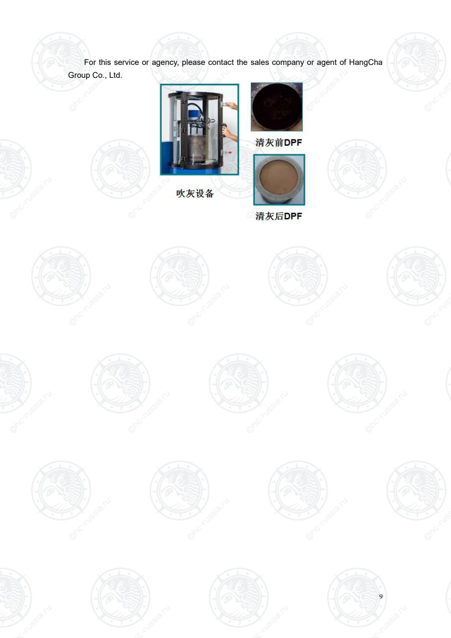
1. Summarize
Driving system is composed of drive axle, final drive, drive shaft, hydraulic transmission box
and cooling pipeline etc. The power from engine acts on hydraulic transmission box, through drive
shaft transfers to final drive, and then the power come to axle shaft by differential, axle shaft drive
tires to run.
Hydraulic transmission box can change the rotated direction of output shaft to drive truck to
move forward and backward.
T=33N ·m ~ 45N ·m
T=45N ·m ~ 59N ·m
T=58N ·m ~ 78N ·m
T=441N ·m ~539N ·m
1 2
9
3
4, 5, 6 7
8
10
11 12 13
14
15,16,17
Fig.2-1-1 Hydraulic Forklift Drive system
1. Bolt 2. Washer 3. Drive axle 4.pin 5. Stud
6. Nut 7. Hydraulic gearbox 8. Tire assembly 9.Washer 10. Bolt
11.Rubber hose 12.Hydraulic Filtration 13. Rubber hose 14.Rubber hose 15. Washer
16.Nut 17.Bolt
Оригинальная страница: таблицы и схемы
Страница 16
11
15 16
16 17 18
2
3
1
10
11
12
4
5 6
7 8 9
T=363N·m~490N·m
14
13
T=120N·m~140N·m
T=120N·m~140N·m
7 8 9
T=441N·m~539N·m
T=441N·m~539N·m
T=120N·m~140N·m
T=58N·m~78N·m
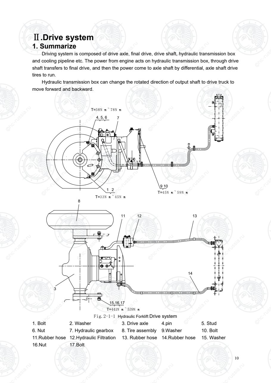
图 2-1-2 机械车
1. Drive axle 2. Washer 3. Bolt 4. Nuts 5. Rim-assy
6. Tyre 7. Washer 8. Nuts 9. Bolt 10. Nuts
11. Washer 12. Bolt 13. Drive shaft
assembly
14. Mechanical
gearbox 15. Bolt
16. Washer 17. Bolt 18. Pin
Оригинальная страница: таблицы и схемы
Страница 17
12
2. Hydrodynamic power transmission gear-box
1.Domestic hydrodynamic power transmission gear-box:
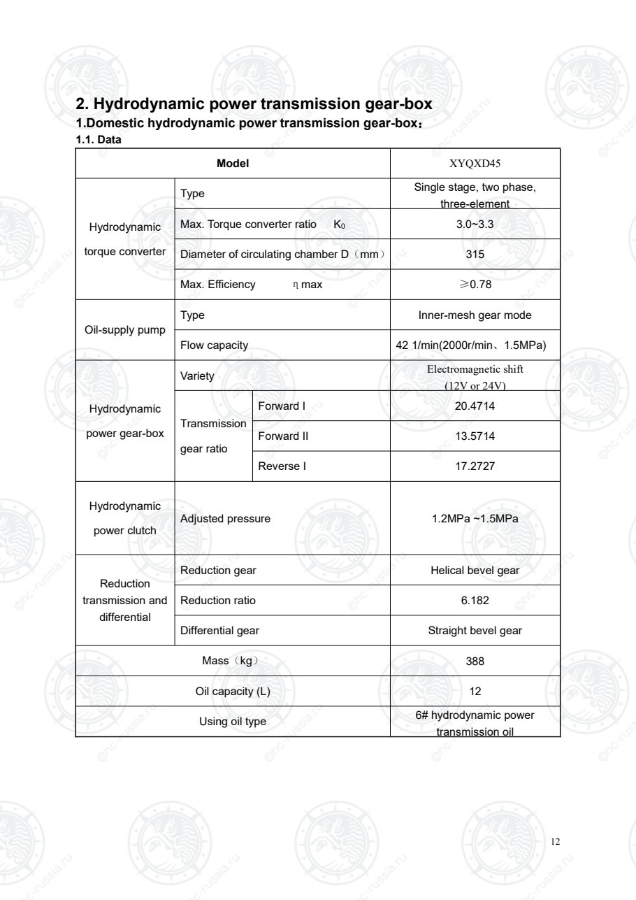
1.1. Data
Model XYQXD45
Hydrodynamic
torque converter
Type Single stage, two phase,
three-element
Max. Torque converter ratio K0 3.0~3.3
Diameter of circulating chamber D(mm) 315
Max. Efficiency ηmax ≥0.78
Oil-supply pump
Type Inner-mesh gear mode
Flow capacity 42 1/min(2000r/min、1.5MPa)
Hydrodynamic
power gear-box
Variety Electromagnetic shift
(12V or 24V)
Transmission
gear ratio
Forward I 20.4714
Forward II 13.5714
Reverse I 17.2727
Hydrodynamic
power clutch
Adjusted pressure 1.2MPa ~1.5MPa
Reduction
transmission and
differential
Reduction gear Helical bevel gear
Reduction ratio 6.182
Differential gear Straight bevel gear
Mass(kg) 388
Oil capacity (L) 12
Using oil type 6# hydrodynamic power
transmission oil
Оригинальная страница: таблицы и схемы
Страница 18
13
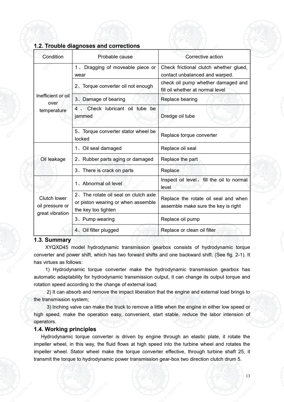
1.2. Trouble diagnoses and corrections
Condition Probable cause Corrective action
Inefficient or oil
over
temperature
1、 Dragging of moveable piece or
wear
Check frictional clutch whether glued,
contact unbalanced and warped.
2、Torque converter oil not enough check oil pump whether damaged and
fill oil whether at normal level
3、Damage of bearing Replace bearing
4 、 Check lubricant oil tube be
jammed Dredge oil tube
5、Torque converter stator wheel be
locked Replace torque converter
Oil leakage
1、Oil seal damaged Replace oil seal
2、Rubber parts aging or damaged Replace the part
3、There is crack on parts Replace
Clutch lower
oil pressure or
great vibration
1、Abnormal oil level Inspect oil level, fill the oil to normal
level
2、The rotate oil seal on clutch axle
or piston wearing or when assemble
the key too tighten
Replace the rotate oil seal and when
assemble make sure the key is right
3、Pump wearing Replace oil pump
4、Oil filter plugged Replace or clean oil filter
1.3. Summary
XYQXD45 model hydrodynamic transmission gearbox consists of hydrodynamic torque
converter and power shift, which has two forward shifts and one backward shift. (See fig. 2-1). It
has virtues as follows:
1) Hydrodynamic torque converter make the hydrodynamic transmission gearbox has
automatic adaptability for hydrodynamic transmission output, it can change its output torque and
rotation speed according to the change of external load;
2) It can absorb and remove the impact liberation that the engine and external load brings to
the transmission system;
3) Inching valve can make the truck to remove a little when the engine in either low speed or
high speed, make the operation easy, convenient, start stable, reduce the labor intension of
operators.
1.4. Working principles
Hydrodynamic torque converter is driven by engine through an elastic plate, it rotate the
impeller wheel, in this way, the fluid flows at high speed into the turbine wheel and rotates the
impeller wheel. Stator wheel make the torque converter effective, through turbine shaft 25, it
transmit the torque to hydrodynamic power transmission gear-box two direction clutch drum 5.
Оригинальная страница: таблицы и схемы
Страница 19
14
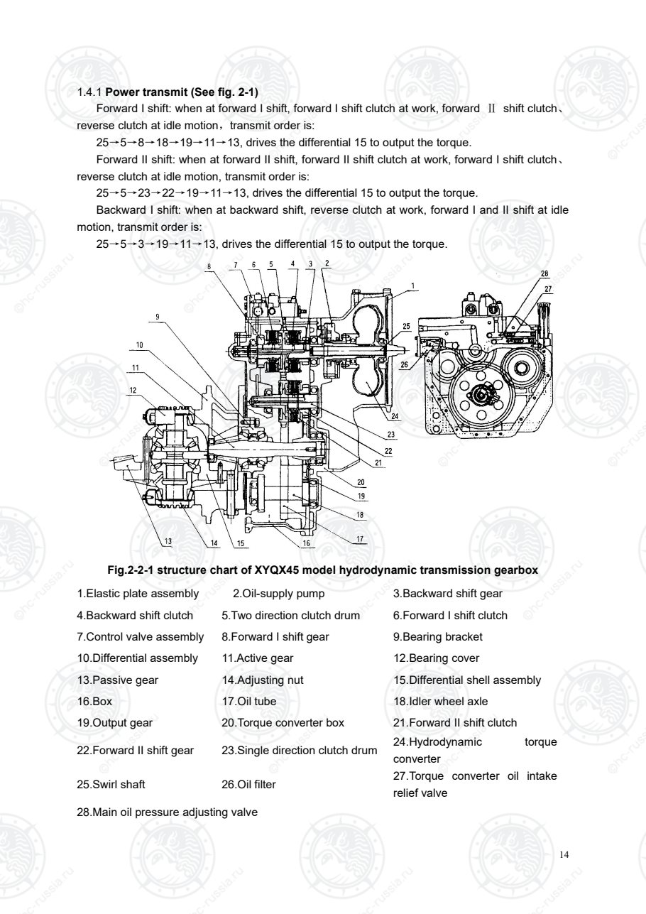
1.4.1 Power transmit (See fig. 2-1)
Forward I shift: when at forward I shift, forward I shift clutch at work, forward Ⅱ shift clutch、
reverse clutch at idle motion,transmit order is:
25→5→8→18→19→11→13, drives the differential 15 to output the torque.
Forward II shift: when at forward II shift, forward II shift clutch at work, forward I shift clutch、
reverse clutch at idle motion, transmit order is:
25→5→23→22→19→11→13, drives the differential 15 to output the torque.
Backward I shift: when at backward shift, reverse clutch at work, forward I and II shift at idle
motion, transmit order is:
25→5→3→19→11→13, drives the differential 15 to output the torque.

Fig.2-2-1 structure chart of XYQX45 model hydrodynamic transmission gearbox
1.Elastic plate assembly 2.Oil-supply pump 3.Backward shift gear
4.Backward shift clutch 5.Two direction clutch drum 6.Forward I shift clutch
7.Control valve assembly 8.Forward I shift gear 9.Bearing bracket
10.Differential assembly 11.Active gear 12.Bearing cover
13.Passive gear 14.Adjusting nut 15.Differential shell assembly
16.Box 17.Oil tube 18.Idler wheel axle
19.Output gear 20.Torque converter box 21.Forward II shift clutch
22.Forward II shift gear 23.Single direction clutch drum 24.Hydrodynamic torque
converter
25.Swirl shaft 26.Oil filter 27.Torque converter oil intake
relief valve
28.Main oil pressure adjusting valve
Оригинальная страница: таблицы и схемы
Страница 20
15
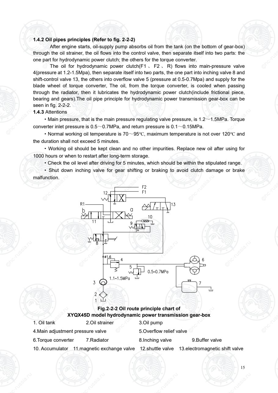
1.4.2 Oil pipes principles (Refer to fig. 2-2-2)
After engine starts, oil-supply pump absorbs oil from the tank (on the bottom of gear-box)
through the oil strainer, the oil flows into the control valve, then separate itself into two parts: the
one part for hydrodynamic power clutch; the others for the torque converter.
The oil for hydrodynamic power clutch(F1 、 F2 、 R) flows into main-pressure valve
4(pressure at 1.2-1.5Mpa), then separate itself into two parts, the one part into inching valve 8 and
shift-control valve 13, the others into overflow valve 5 (pressure at 0.5-0.7Mpa) and supply for the
blade wheel of torque converter, The oil, from the torque converter, is cooled when passing
through the radiator, then it lubricates the hydrodynamic power clutch(include frictional piece,
bearing and gears).The oil pipe principle for hydrodynamic power transmission gear-box can be
seen in fig. 2-2-2.
1.4.3 Attentions
·Main pressure, that is the main pressure regulating valve pressure, is 1.2~1.5MPa. Torque
converter inlet pressure is 0.5~0.7MPa, and return pressure is 0.1~0.15MPa.
·Normal working oil temperature is 70~95℃, maximum temperature is not over 120℃ and
the duration shall not exceed 5 minutes.
·Working oil should be kept clean and no other impurities. Replace new oil after using for
1000 hours or when to restart after long-term storage.
·Check the oil level after driving for 5 minutes, which should be within the stipulated range.
· Shut down inching valve for gear shifting or braking to avoid clutch damage or brake
malfunction.
Fig.2-2-2 Oil route principle chart of
XYQX45D model hydrodynamic power transmission gear-box
1. Oil tank 2.Oil strainer 3.Oil pump
4.Main adjustment pressure valve 5.Overflow relief valve
6.Torque converter 7.Radiator 8.Inching valve 9.Buffer valve
10. Accumulator 11.magnetic exchange valve 12.shuttle valve 13.electromagnetic shift valve
Оригинальная страница: таблицы и схемы
Страница 21
16
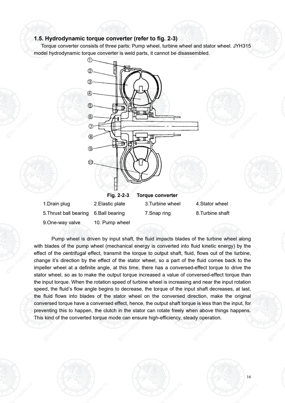
1.5. Hydrodynamic torque converter (refer to fig. 2-3)
Torque converter consists of three parts: Pump wheel, turbine wheel and stator wheel. JYH315
model hydrodynamic torque converter is weld parts, it cannot be disassembled.
Fig. 2-2-3 Torque converter
1.Drain plug 2.Elastic plate 3.Turbine wheel 4.Stator wheel
5.Thrust ball bearing 6.Ball bearing 7.Snap ring 8.Turbine shaft
9.One-way valve 10. Pump wheel
Pump wheel is driven by input shaft, the fluid impacts blades of the turbine wheel along
with blades of the pump wheel (mechanical energy is converted into fluid kinetic energy) by the
effect of the centrifugal effect, transmit the torque to output shaft, fluid, flows out of the turbine,
change it’s direction by the effect of the stator wheel, so a part of the fluid comes back to the
impeller wheel at a definite angle, at this time, there has a conversed-effect torque to drive the
stator wheel, so as to make the output torque increased a value of conversed-effect torque than
the input torque. When the rotation speed of turbine wheel is increasing and near the input rotation
speed, the fluid’s flow angle begins to decrease, the torque of the input shaft decreases, at last,
the fluid flows into blades of the stator wheel on the conversed direction, make the original
conversed torque have a conversed effect, hence, the output shaft torque is less than the input, for
preventing this to happen, the clutch in the stator can rotate freely when above things happens.
This kind of the converted torque mode can ensure high-efficiency, steady operation.
Оригинальная страница: таблицы и схемы
Страница 22
17
1.6. Bidirectional clutch and single direction clutch
1.6.1 Summarize
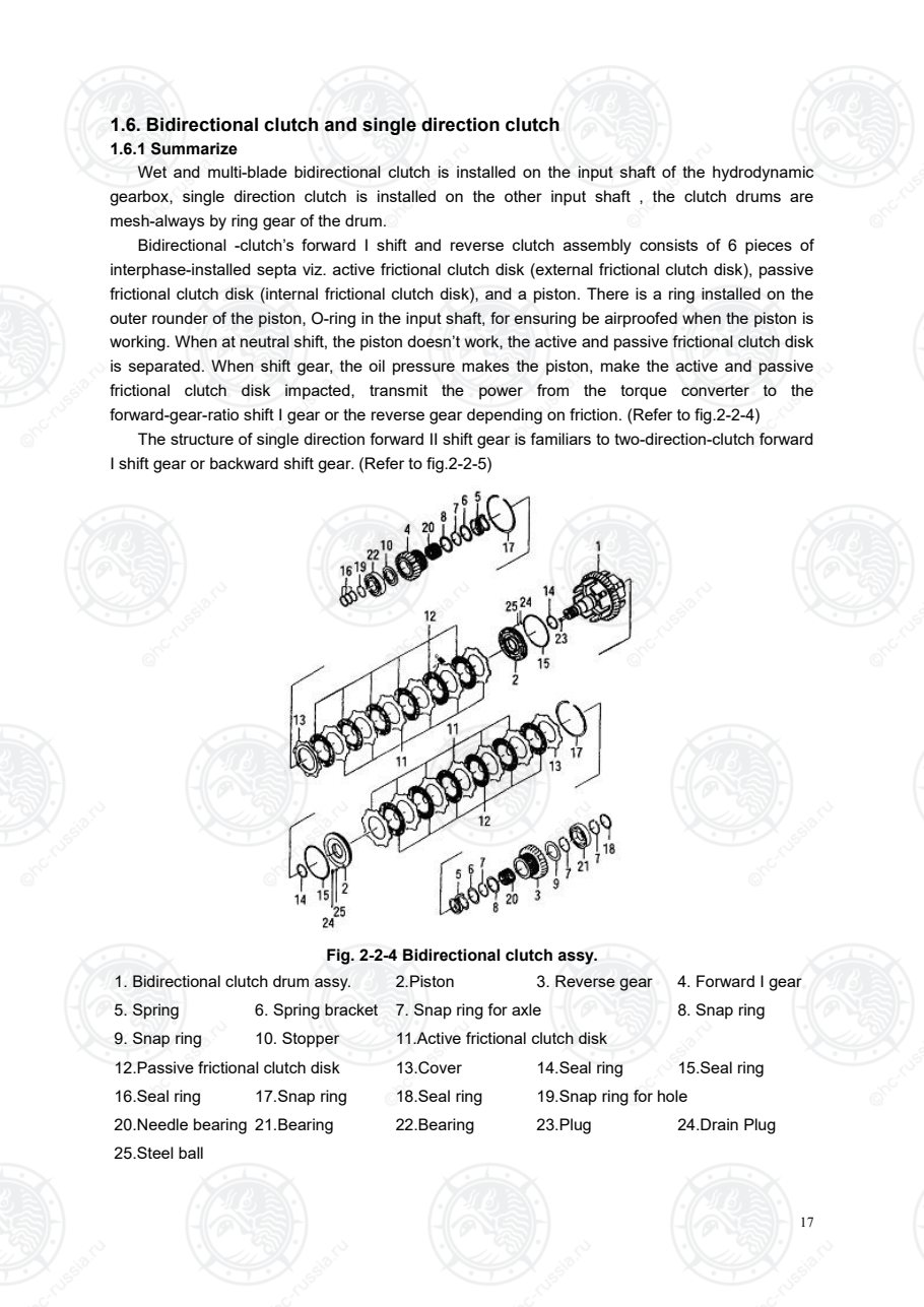
Wet and multi-blade bidirectional clutch is installed on the input shaft of the hydrodynamic
gearbox, single direction clutch is installed on the other input shaft , the clutch drums are
mesh-always by ring gear of the drum.
Bidirectional -clutch’s forward I shift and reverse clutch assembly consists of 6 pieces of
interphase-installed septa viz. active frictional clutch disk (external frictional clutch disk), passive
frictional clutch disk (internal frictional clutch disk), and a piston. There is a ring installed on the
outer rounder of the piston, O-ring in the input shaft, for ensuring be airproofed when the piston is
working. When at neutral shift, the piston doesn’t work, the active and passive frictional clutch disk
is separated. When shift gear, the oil pressure makes the piston, make the active and passive
frictional clutch disk impacted, transmit the power from the torque converter to the
forward-gear-ratio shift I gear or the reverse gear depending on friction. (Refer to fig.2-2-4)
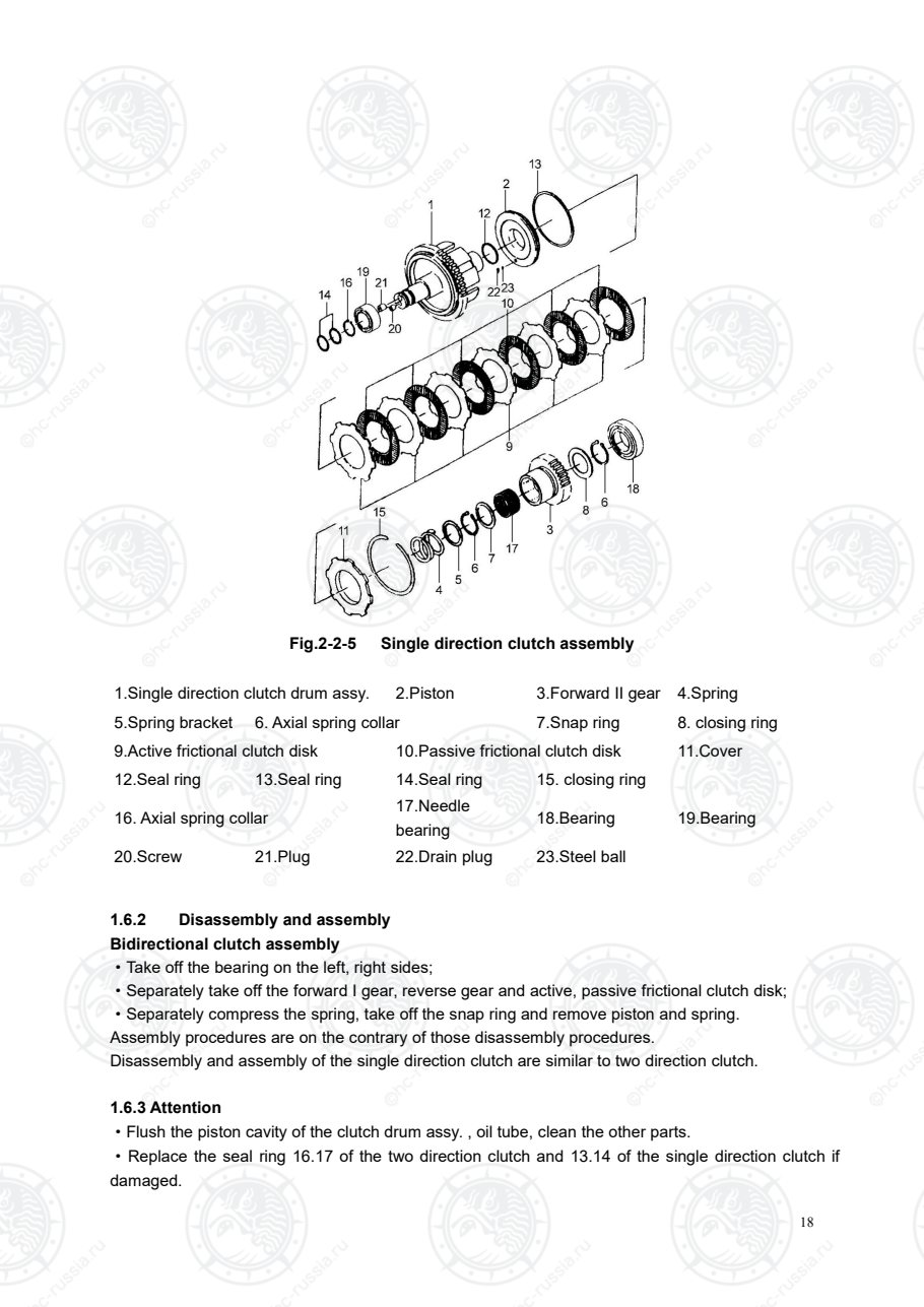
The structure of single direction forward II shift gear is familiars to two-direction-clutch forward
I shift gear or backward shift gear. (Refer to fig.2-2-5)
Fig. 2-2-4 Bidirectional clutch assy.
1. Bidirectional clutch drum assy. 2.Piston 3. Reverse gear 4. Forward I gear
5. Spring 6. Spring bracket 7. Snap ring for axle 8. Snap ring
9. Snap ring 10. Stopper 11.Active frictional clutch disk
12.Passive frictional clutch disk 13.Cover 14.Seal ring 15.Seal ring
16.Seal ring 17.Snap ring 18.Seal ring 19.Snap ring for hole
20.Needle bearing 21.Bearing 22.Bearing 23.Plug 24.Drain Plug
25.Steel ball
Оригинальная страница: таблицы и схемы
Страница 23
18
Fig.2-2-5 Single direction clutch assembly
1.Single direction clutch drum assy. 2.Piston 3.Forward II gear 4.Spring
5.Spring bracket 6. Axial spring collar 7.Snap ring 8. closing ring
9.Active frictional clutch disk 10.Passive frictional clutch disk 11.Cover
12.Seal ring 13.Seal ring 14.Seal ring 15. closing ring
16. Axial spring collar 17.Needle
bearing 18.Bearing 19.Bearing
20.Screw 21.Plug 22.Drain plug 23.Steel ball
1.6.2 Disassembly and assembly
Bidirectional clutch assembly
·Take off the bearing on the left, right sides;
·Separately take off the forward I gear, reverse gear and active, passive frictional clutch disk;
·Separately compress the spring, take off the snap ring and remove piston and spring.
Assembly procedures are on the contrary of those disassembly procedures.
Disassembly and assembly of the single direction clutch are similar to two direction clutch.
1.6.3 Attention
·Flush the piston cavity of the clutch drum assy. , oil tube, clean the other parts.
·Replace the seal ring 16.17 of the two direction clutch and 13.14 of the single direction clutch if
damaged.
Оригинальная страница: таблицы и схемы
Страница 24
19
·Usually replace snap ring for hole.
·Replace rubber seal ring.
·Restrained ring (slotted side) should face to gears.
·After assembled, rotate the gears with hands, it should be freely rather than locked.
1.7. Control valve assembly, main pressure regulating valve and relief valve
1.7.1 Control valve assembly
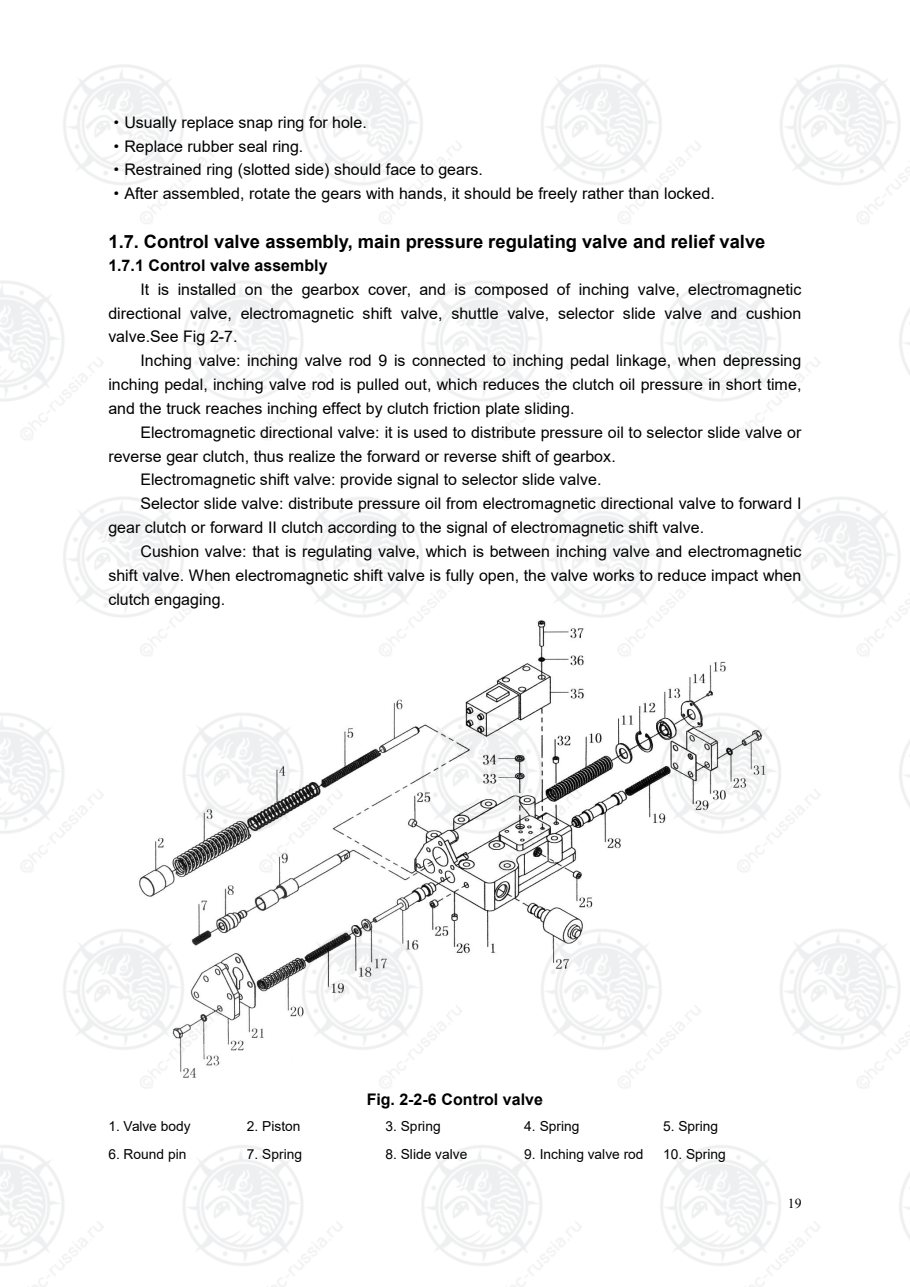
It is installed on the gearbox cover, and is composed of inching valve, electromagnetic
directional valve, electromagnetic shift valve, shuttle valve, selector slide valve and cushion
valve.See Fig 2-7.
Inching valve: inching valve rod 9 is connected to inching pedal linkage, when depressing
inching pedal, inching valve rod is pulled out, which reduces the clutch oil pressure in short time,
and the truck reaches inching effect by clutch friction plate sliding.
Electromagnetic directional valve: it is used to distribute pressure oil to selector slide valve or
reverse gear clutch, thus realize the forward or reverse shift of gearbox.
Electromagnetic shift valve: provide signal to selector slide valve.
Selector slide valve: distribute pressure oil from electromagnetic directional valve to forward I
gear clutch or forward II clutch according to the signal of electromagnetic shift valve.
Cushion valve: that is regulating valve, which is between inching valve and electromagnetic
shift valve. When electromagnetic shift valve is fully open, the valve works to reduce impact when
clutch engaging.
Fig. 2-2-6 Control valve
1. Valve body 2. Piston 3. Spring 4. Spring 5. Spring
6. Round pin 7. Spring 8. Slide valve 9. Inching valve rod 10. Spring
Оригинальная страница: таблицы и схемы
Страница 25
20
11. Gasket 12. Check ring 13. Oil seal 14. Gland 15. Screw
16. Inching valve
element
17.Adjusting shim 18. Gasket 19. Spring 20. Spring
21. Gasket 22. Cover 23. Gasket 24. Bolt 25. Taper plug
26 Plug
27.Electromagnetic
shift valve
28. Slide valve 29. Gasket 30. Cover
31. Bolt 32. Taper plug 33. O-ring 34. Strainer
35.Electromagnetic
directional valve
36. Gasket 37. Screw
1.7.2 Main pressure regulating valve (Refer to fig.2-2-1)
Main pressure regulating valve 28 is installed inside the gearbox shell body, the oil
pressure for controlling the hydrodynamic clutch is at 1.2Mpa -1.5Mpa, assigns the oil to the relief
valve, then to torque converter.
1.7.3 Relief valve (Refer to fig.2-2-1)
Relief valve 27 connects to gearbox shell body, keep the oil pressure for torque converter
between 0.5Mpa -0.7Mpa, prevent the air erode, prevent the air erode.
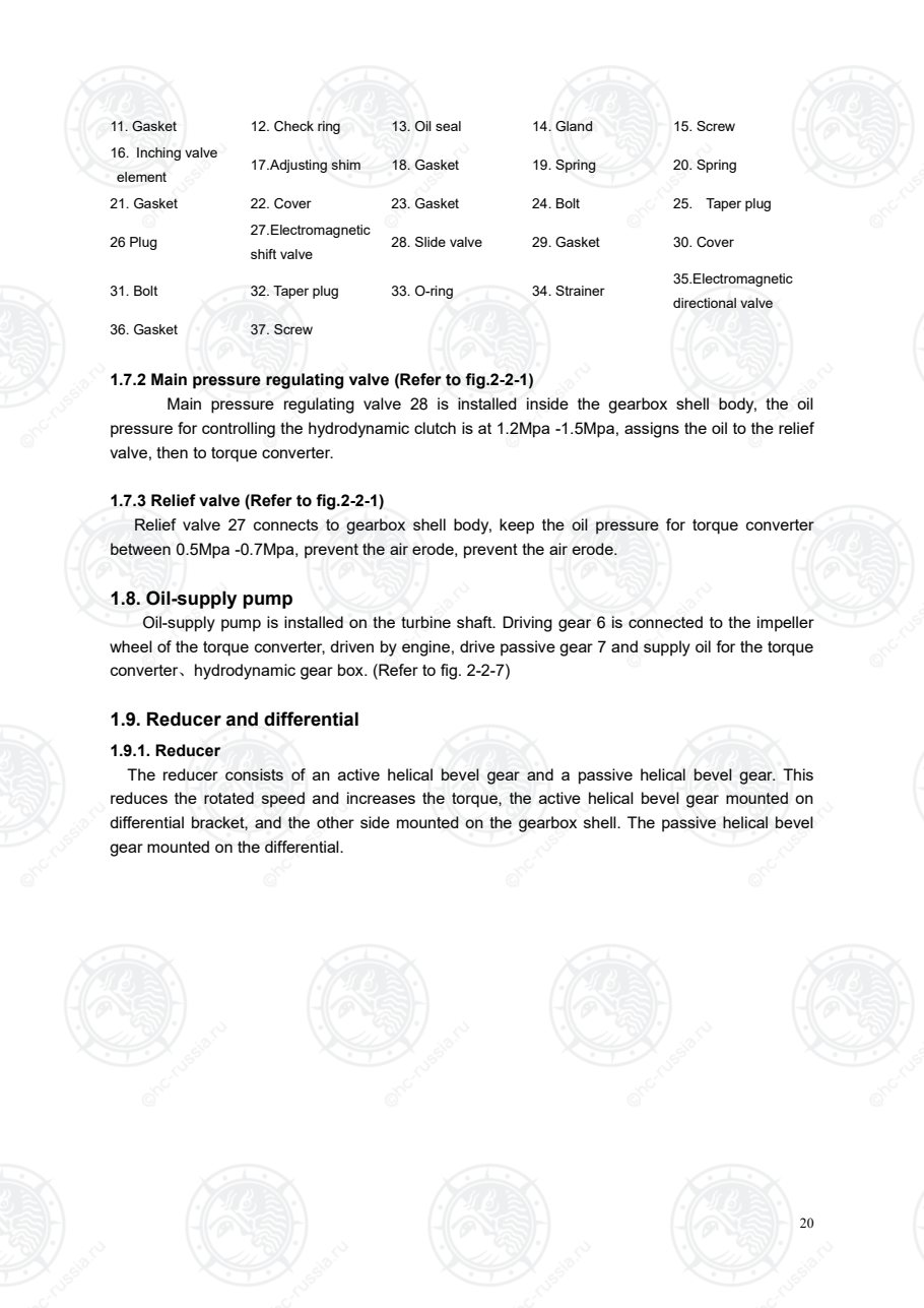
1.8. Oil-supply pump
Oil-supply pump is installed on the turbine shaft. Driving gear 6 is connected to the impeller
wheel of the torque converter, driven by engine, drive passive gear 7 and supply oil for the torque
converter、hydrodynamic gear box. (Refer to fig. 2-2-7)
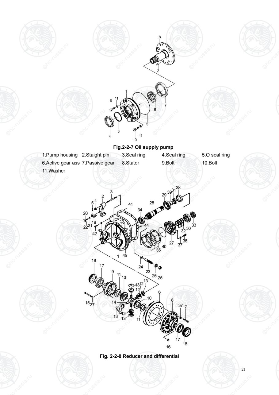
1.9. Reducer and differential
1.9.1. Reducer
The reducer consists of an active helical bevel gear and a passive helical bevel gear. This
reduces the rotated speed and increases the torque, the active helical bevel gear mounted on
differential bracket, and the other side mounted on the gearbox shell. The passive helical bevel
gear mounted on the differential.
Оригинальная страница: таблицы и схемы
Страница 26
21
Fig.2-2-7 Oil supply pump
1.Pump housing 2.Staight pin 3.Seal ring 4.Seal ring 5.O seal ring
6.Active gear assy.7.Passive gear 8.Stator 9.Bolt 10.Bolt
11.Washer
Fig. 2-2-8 Reducer and differential
Оригинальная страница: таблицы и схемы
Страница 27
22
1.Differential velocity frame 2.Bearing cover 6.Passive helical gear
8.Left differential gear case 9.Right differential gear case 11.Washer
12.Planetary pinion 3.Thrust bearing 14.Corse axle 17.Tapered roller bearings
18.Adjusting nut 19.Lock shim 20.Bolt with hole 22.Steel wire 23.Bolt
24.Slide piece 25.Nut 26.Stop shim 27.Bearing
bracket
28.Active helical gear 29.Tapered roller bearings
30.Tapered roller bearings 31. sleeve gasket 32.Adjusting nut 33.Nut
34.Tapered roller bearings 35.Adjusting shim 38.Bidirectional seal ring
39.O ring 40.O ring 41.Paper shim
1.9.2 Differential case
Differential case is installed on the rack of differential by bearing holder through ball bearing on
both ends. Differential carriage is divided into left and right half, which is composed of two semi-axle
gears and four planetary gears, thrust ring is put between differential carriage and gears in order to
have a clearance between pairs of gears, planetary gears is braced by corse axle、passive helical
bevel gear is installed on differential shell by bolt.
1.9.3 Disassembly
Disassembly Procedure
① Remove the bearing bracket, take out the active helical gear and detach the active gear assy.
② Detach the bearing bracket (2 pieces), take off the differential assy.
③ Detach the differential assy.
Caution
Pay attention to reassemble:
① It can adjust the meshing area and height of the active and passive helical gears by
additions and deletions adjusting shims 35 and adjust adjusting nut 18.
② Pre-tighten of the tapered roll bearings 17, you can adjust the adjusting nut.
③ When bolt 23 is tighten to withstand the passive helical gear, loosen the nut 1/6-1/4
round.
④ At active helical gear assy., you can adjust Pre-tighten of the bearing 29 、30 by additions
and deletions adjusting shims 32.
⑤ Usually replace O-rings.
⑥After assembly, it is forbidden for parts interfere or there is abnormal noise.
1.10. Disassembly of hydrodynamic power transmission gear-box, hydrodynamic torque
converter
Open the oil plug, and drain the oil, detach the parts as following sequence:
Differential→ oil pump assy.→ suck oil pipe assy.→ idle pinion shaft, output gear→ torque
Оригинальная страница: таблицы и схемы
Страница 28
23
converter shell assy. →single direction clutch assy. →two direction clutch assy. →control valve
assy.
Оригинальная страница: таблицы и схемы

Страница 29
24
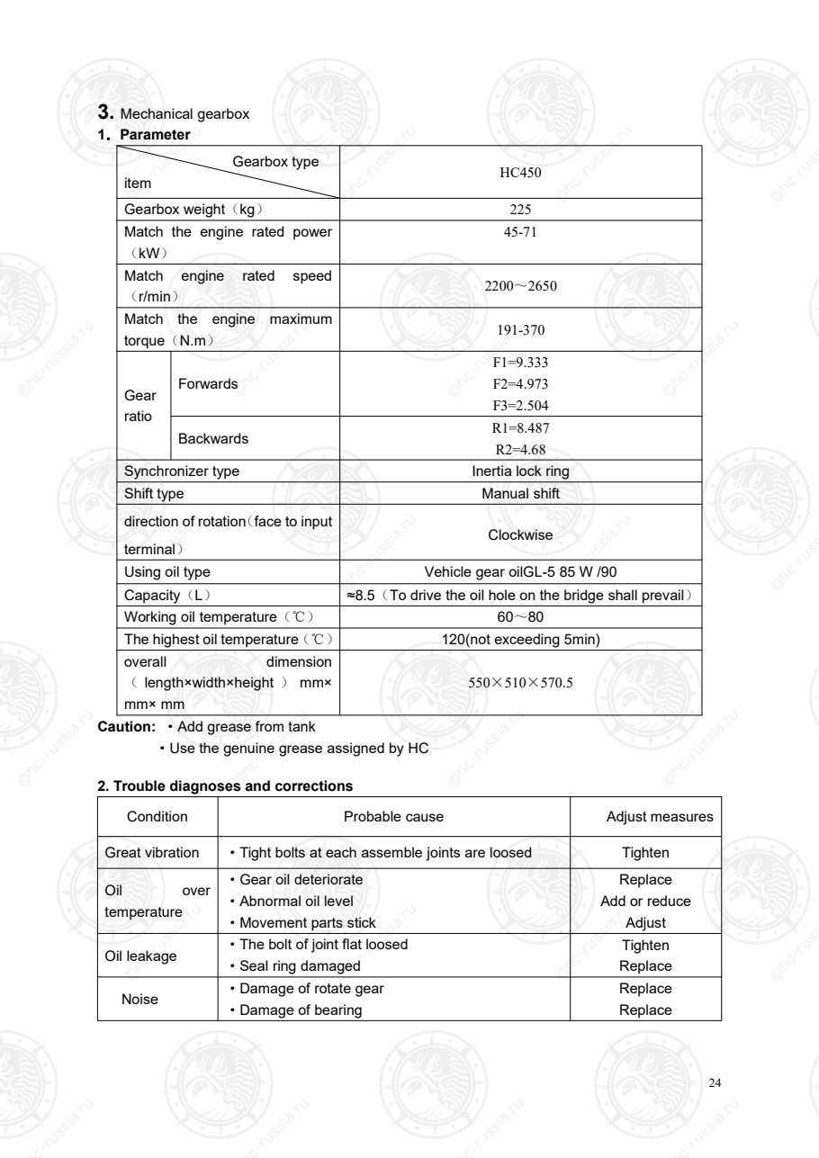
3. Mechanical gearbox
1.Parameter
Gearbox type
item HC450
Gearbox weight(kg) 225
Match the engine rated power
(kW)
45-71
Match engine rated speed
(r/min) 2200~2650
Match the engine maximum
torque(N.m) 191-370
Gear
ratio
Forwards
F1=9.333
F2=4.973
F3=2.504
Backwards R1=8.487
R2=4.68
Synchronizer type Inertia lock ring
Shift type Manual shift
direction of rotation(face to input
terminal)
Clockwise
Using oil type Vehicle gear oilGL-5 85 W /90
Capacity(L) ≈8.5(To drive the oil hole on the bridge shall prevail)
Working oil temperature(℃) 60~80
The highest oil temperature(℃) 120(not exceeding 5min)
overall dimension
( length×width×height ) mm×
mm× mm
550×510×570.5
Caution: ·Add grease from tank
·Use the genuine grease assigned by HC
2. Trouble diagnoses and corrections
Condition Probable cause Adjust measures
Great vibration ·Tight bolts at each assemble joints are loosed Tighten
Oil over
temperature
·Gear oil deteriorate
·Abnormal oil level
·Movement parts stick
Replace
Add or reduce
Adjust
Oil leakage ·The bolt of joint flat loosed
·Seal ring damaged
Tighten
Replace
Noise ·Damage of rotate gear
·Damage of bearing
Replace
Replace
Оригинальная страница: таблицы и схемы
Страница 30
25
3. Summary
The mechanical gearbox of 4 ton -5 ton mechanical forklift has shift and transmit functions. The
mechanical gearbox adopt three forward shifts, two backward shifts, it is reasonable for
Transmission ratio, the forklift can obtain more traction force when it is at low range, high range
has high drive speed, it can promote forklift’s performance parameter and efficiency.
On structure, adopt the structure that output from the tank with universal joint, it overcome the
phenomenon that engine, gearbox and driving axle rigid coupling vibrate effectively, the whole
longitudinal dimension of tank is compact. It is installed synchronizer, it can avoid ram at gear
when shift, especially when change direction, t can make shift soft, stable and reduce noise of shift,
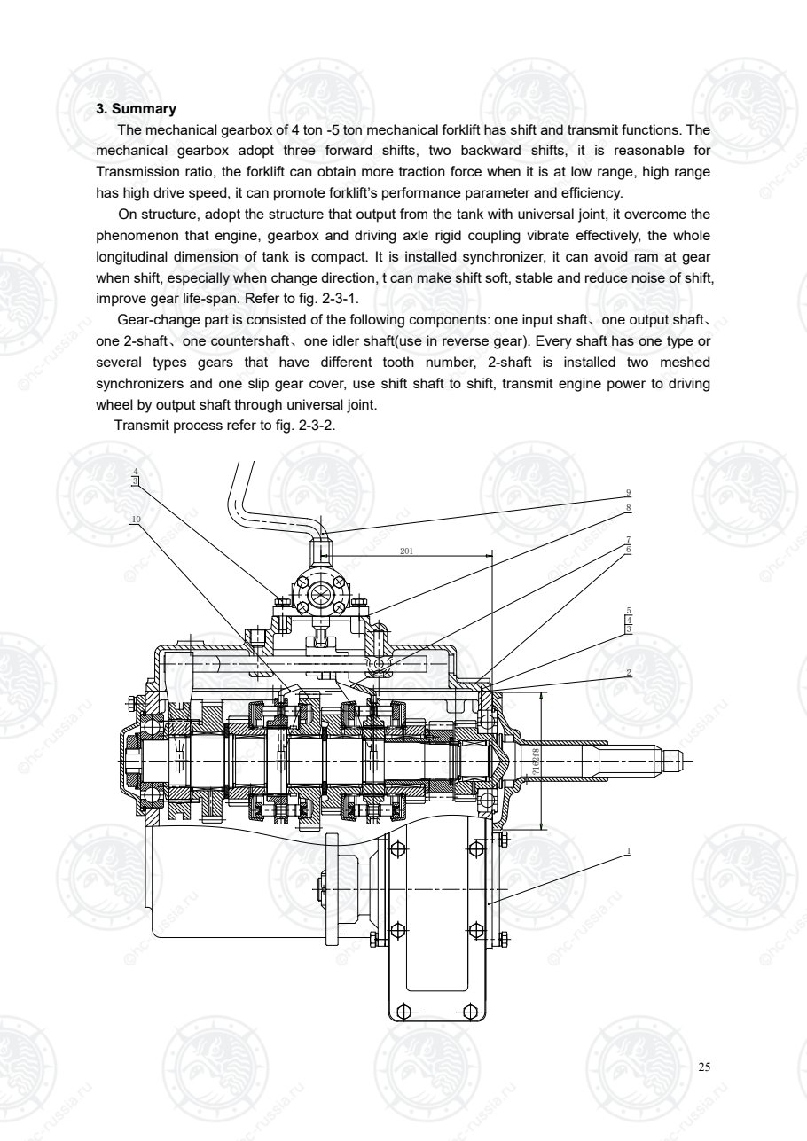
improve gear life-span. Refer to fig. 2-3-1.
Gear-change part is consisted of the following components: one input shaft、one output shaft、
one 2-shaft、one countershaft、one idler shaft(use in reverse gear). Every shaft has one type or
several types gears that have different tooth number, 2-shaft is installed two meshed
synchronizers and one slip gear cover, use shift shaft to shift, transmit engine power to driving
wheel by output shaft through universal joint.
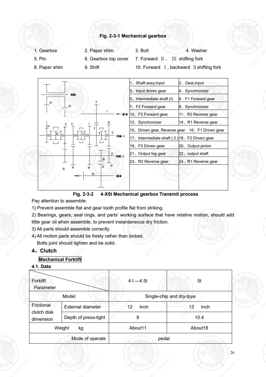
Transmit process refer to fig. 2-3-2.
?162f8
201
1
2
3
4
5
6
7
8
9
3
4
10
Оригинальная страница: таблицы и схемы
Страница 31
26
Fig. 2-3-1 Mechanical gearbox
1. Gearbox 2. Paper shim 3. Bolt 4. Washer
5. Pin 6. Gearbox top cover 7. Forward Ⅱ、 Ⅲ shifting fork
8. Paper shim 9. Shift 10. Forward Ⅰ, backward Ⅱshifting fork
1、Shaft assy,Input 2、Gear,input
3、Input driven gear 4、Synchronizer
5、Intermediate shaft (I) 6、F1 Forward gear
7、F2 Forward gear 8、Synchronizer
10、F3 Forward gear 11、R2 Reverse gear
12、Synchronizer 14、R1 Reverse gear
15、Driven gear, Reverse gear 16、F1 Driven gear
17、Intermediate shaft (Ⅱ) 18、F2 Driven gear
19、F3 Driven gear 20、Output pinion
21、Output big gear 22、output shaft
23、R2 Reverse gear 24、R1 Reverse gear
Fig. 2-3-2 4-X5t Mechanical gearbox Transmit process
Pay attention to assemble:
1) Prevent assemble flat and gear tooth profile flat from striking.
2) Bearings, gears, seal rings, and parts’ working surface that have relative motion, should add
little gear oil when assemble, to prevent instantaneous dry friction.
3) All parts should assemble correctly.
4) All motion parts should be freely rather than locked.
Bolts joint should tighten and be solid.
4、Clutch
Mechanical Forklift
4.1. Data
Forklift
Parameter
4 t ---4.5t 5t
Model Single-chip and dry-tpye
Frictional
clutch disk
dimension
External diameter 12 Inch 13 Inch
Depth of press-tight 9 10.4
Weight kg About11 About18
Mode of operate pedal
Оригинальная страница: таблицы и схемы
Страница 32
27
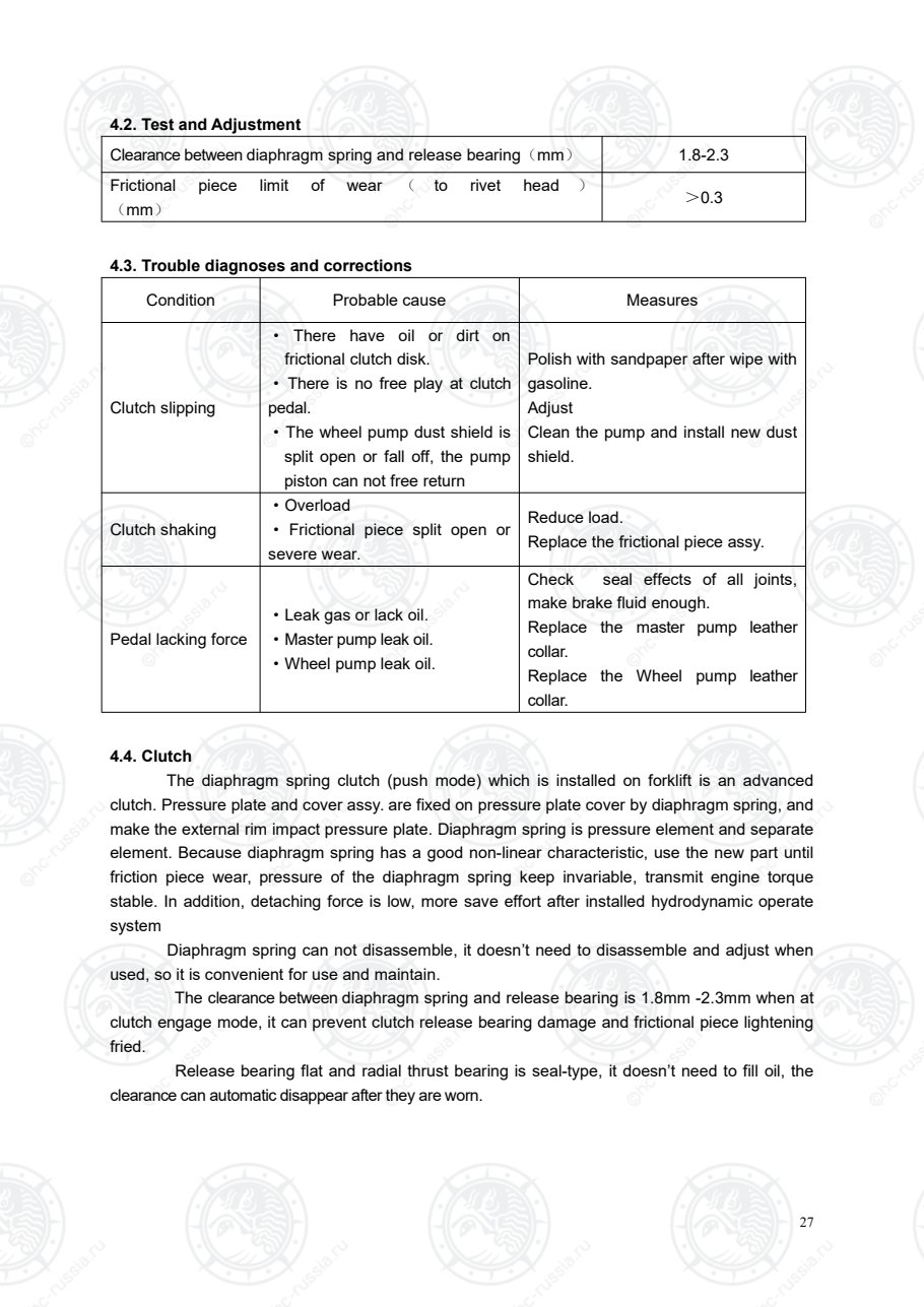
4.2. Test and Adjustment
Clearance between diaphragm spring and release bearing(mm) 1.8-2.3
Frictional piece limit of wear ( to rivet head )
(mm) >0.3
4.3. Trouble diagnoses and corrections
Condition Probable cause Measures
Clutch slipping
· There have oil or dirt on
frictional clutch disk.
· There is no free play at clutch
pedal.
·The wheel pump dust shield is
split open or fall off, the pump
piston can not free return
Polish with sandpaper after wipe with
gasoline.
Adjust
Clean the pump and install new dust
shield.
Clutch shaking
·Overload
· Frictional piece split open or
severe wear.
Reduce load.
Replace the frictional piece assy.
Pedal lacking force
·Leak gas or lack oil.
·Master pump leak oil.
·Wheel pump leak oil.
Check seal effects of all joints,
make brake fluid enough.
Replace the master pump leather
collar.
Replace the Wheel pump leather
collar.
4.4. Clutch
The diaphragm spring clutch (push mode) which is installed on forklift is an advanced
clutch. Pressure plate and cover assy. are fixed on pressure plate cover by diaphragm spring, and
make the external rim impact pressure plate. Diaphragm spring is pressure element and separate
element. Because diaphragm spring has a good non-linear characteristic, use the new part until
friction piece wear, pressure of the diaphragm spring keep invariable, transmit engine torque
stable. In addition, detaching force is low, more save effort after installed hydrodynamic operate
system
Diaphragm spring can not disassemble, it doesn’t need to disassemble and adjust when
used, so it is convenient for use and maintain.
The clearance between diaphragm spring and release bearing is 1.8mm -2.3mm when at
clutch engage mode, it can prevent clutch release bearing damage and frictional piece lightening
fried.
Release bearing flat and radial thrust bearing is seal-type, it doesn’t need to fill oil, the
clearance can automatic disappear after they are worn.
Оригинальная страница: таблицы и схемы
Страница 33
28
4.5. Check and adjust
Clutch release means the clearance between clutch release bearings’ transverse is 1.8mm
-2.3mm, the clearance can prevent clutch release bearing damage and frictional piece lightening
fried. Because forklift usually lies in accelerate and change direction, use clutch frequently,
frictional piece wear is fast, it should pay attention to adjust the clearance frequently.
4.6. Replacement of frictional piece assembly
Open machine shield ----disassemble drive axle universal joint bolt ---- disassemble clutch
piping ---- disassemble gearbox’s brace and bolt------loosen engine’s brace and bolt------push
engine flywheel bottom with solid woodblock or jack------hang the gearbox and clutch housing------
disassemble clutch pressure plate------install new frictional piece ----press the pressure plate, don’t
tighten bolt ---- disassemble clutch housing windows of observation----put gearbox and clutch
housing into----aim at frictional piece and input shaft spline, adjust to suitable position, tighten the
pressure plate ----the following assemble steps are opposite to disassemble.
Adjust the clearance of releasing bearings’ transverse to1.8mm -2.3mm when assemble, at the
same time, apply car in common use grease to the place which has relative motion, but the
surface of frictional piece can not have grease. In the mean time vent piping’ air
Оригинальная страница: таблицы и схемы
Страница 34
29
3. Driving axle
1). Data
Driving axle type Full floating, axle and truck body direct install, front wheel driving
Wheel hub rotation starting torque at
hub blot N 10~29
Axial gap of wheel bearing mm less than 0.08
2). Trouble diagnoses and corrections
condition Probable cause Corrective action
Abnormal noises
·loose driving axle and body connecting blots.
·loose wheel nut
·worn or damaged wheel hub bearing.
·wheel hub bearing not properly adjusted.
·worn axle shaft spline.
·insufficient lubrication
Tighten.
Tighten.
Replace.
Adjust.
Replace.
Lubricate.
Unstable driving
·loose wheel nut.
·deformed wheel.
·worn or damaged wheel hub bearing.
·loose driving axle and body connecting blots.
·wheel hub bearing not properly adjusted.
·improper tire pressure.
Tighten.
Replace.
Replace.
Tighten.
Adjust.
Adjust.
Oil leakage
·worn or damaged axle shaft oil seal.
·final drive improperly installed.
·loose drain plug.
Replace
Replace gasket.
Tighten.
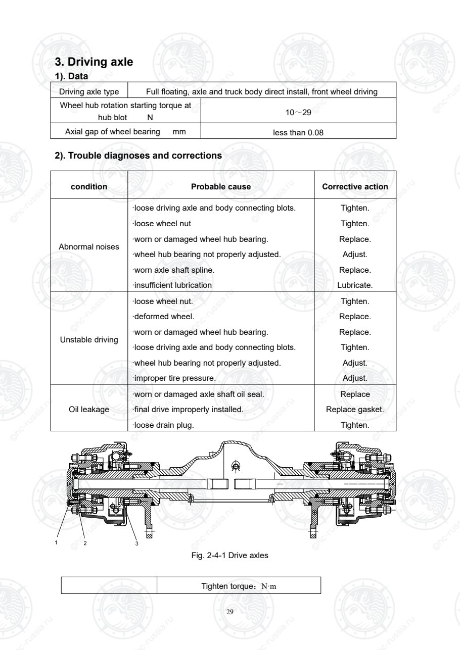
Fig. 2-4-1 Drive axles
Tighten torque:N·m
Оригинальная страница: таблицы и схемы
Страница 35
30
1. Half shaft bolt 110-130
2. Wheel hub nut 324-373
3. Brake base plate bolt 260-300
3). Driving axle assemble removal and installation
! WARNING
Be careful when removal and installation driving axle as it is heavy.
1) Raise front end of forklift truck and support frame with wooden blocks.
2) Remove mast assembles.
3) Slightly raise axle with a hoist and place wooden blacks under differential gear carrier and
transmission case.
4) After placing a pan under axle case, loose oil plug, drain oil from axle case.
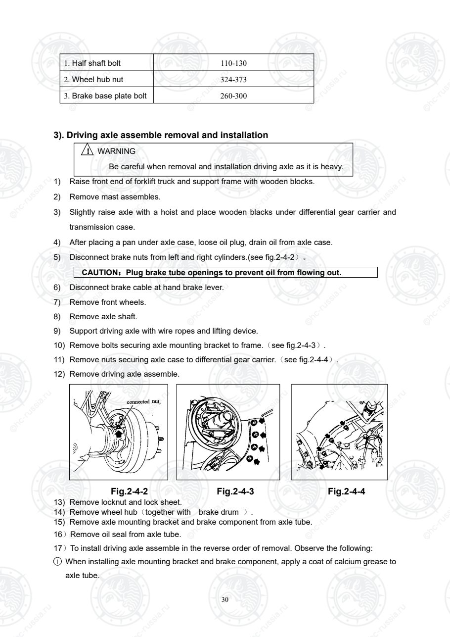
5) Disconnect brake nuts from left and right cylinders.(see fig.2-4-2)。
CAUTION:Plug brake tube openings to prevent oil from flowing out.
6) Disconnect brake cable at hand brake lever.
7) Remove front wheels.
8) Remove axle shaft.
9) Support driving axle with wire ropes and lifting device.
10) Remove bolts securing axle mounting bracket to frame.(see fig.2-4-3).
11) Remove nuts securing axle case to differential gear carrier.(see fig.2-4-4).
12) Remove driving axle assemble.
Fig.2-4-2 Fig.2-4-3 Fig.2-4-4
13) Remove locknut and lock sheet.
14) Remove wheel hub(together with brake drum ).
15) Remove axle mounting bracket and brake component from axle tube.
16)Remove oil seal from axle tube.
17)To install driving axle assemble in the reverse order of removal. Observe the following:
1 When installing axle mounting bracket and brake component, apply a coat of calcium grease to
axle tube.
Оригинальная страница: таблицы и схемы
Страница 36
31
2 Apply 1/3~2/3 of volume of calcium grease to wheel hub,then install them on axle tube.
3 Install oil seal with its part number facing to the inside of forklift truck.
4 attach seal tape (PVC, white)to drain plug then installed after cleaned it.
5 Replenish axle case with gear oil. Tighten vent plug after clearing.
6 Fabrication mill finish directs to bearing when installing locknut.
7 When installing component 17, please smear LOCTITE 222 mucilage (or 242 mucilage ) at
screw thread position(above 2/3) and then loosen.
Ton Models
Fill in drive axle(L)
4-5t Remark
Vehicle gear oil GL-5
85W/90
5.8L Hydraulic Forklift
Vent plug should clear instantly to prevent pressure inside of wheel hub from rising.
4). Axle shaft and wheel hub
Remove
1) Raise the front end of forklift truck and support frame with wooden blocks.
2) Remove front wheel and axle shaft.
3) Remove lock nuts, lock washers, snap ring, felt ring, adjusting nut. Use special tools.
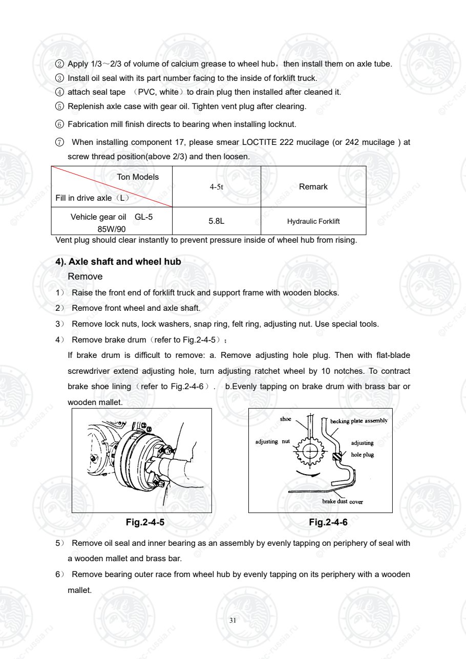
4) Remove brake drum(refer to Fig.2-4-5);
If brake drum is difficult to remove: a. Remove adjusting hole plug. Then with flat-blade
screwdriver extend adjusting hole, turn adjusting ratchet wheel by 10 notches. To contract
brake shoe lining(refer to Fig.2-4-6). b.Evenly tapping on brake drum with brass bar or
wooden mallet.
Fig.2-4-5 Fig.2-4-6
5) Remove oil seal and inner bearing as an assembly by evenly tapping on periphery of seal with
a wooden mallet and brass bar.
6) Remove bearing outer race from wheel hub by evenly tapping on its periphery with a wooden
mallet.
Оригинальная страница: таблицы и схемы
Страница 37
32
CAUTION:Be careful not to damage oil seal and outer race.
Inspection
Stepped wear or cracks on axle shaft splines Replace
Seized, scratched, noisy or rusted bearing or improper rotation of
rollers
Replace
Cracked or damage wheel hub Replace
Damaged oil seal felt ring. Replace
Installation
Install reverse order of removal.
5). Bearing adjusting
1) Lubricate on taper roller bearing.
2) Tighten roller bearing lock nut in wheel hub until wheel hub can no longer be rotated with one
hand.
3) From that position, turn back lock nut approx. 600.
4) Turn back wheel hub two or three rotations so that bearing settles down.
5) Again tighten lock nut until it can no longer be rotated with one hand; then turn back
approx.600.
6) Install snap ring and settles down felt ring, install lock washer so as to set its hole in the pin of
snap ring. Screw lock nut.
7) Turn wheel hub back and forth two or three rotations to see if rotation starting torque is within
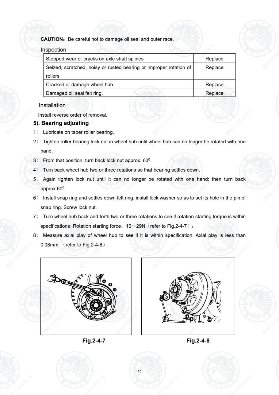
specifications. Rotation starting force:10~29N(refer to Fig.2-4-7);
8) Measure axial play of wheel hub to see if it is within specification. Axial play is less than
0.08mm (refer to Fig.2-4-8).
Fig.2-4-7 Fig.2-4-8
Оригинальная страница: таблицы и схемы
Страница 38
33
Wet drive axle(W76BN、G73BN-S)
1 General
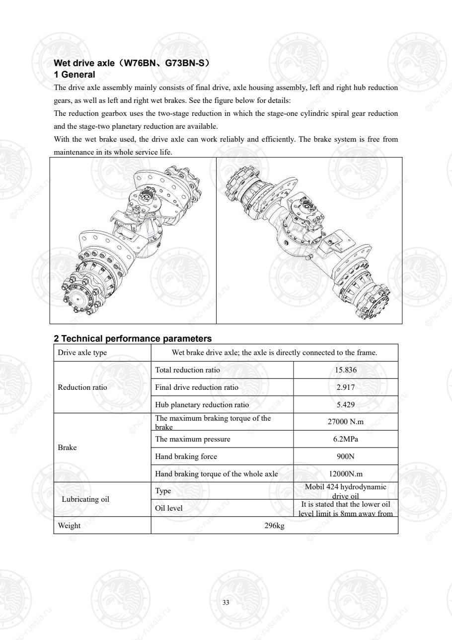
The drive axle assembly mainly consists of final drive, axle housing assembly, left and right hub reduction
gears, as well as left and right wet brakes. See the figure below for details:
The reduction gearbox uses the two-stage reduction in which the stage-one cylindric spiral gear reduction
and the stage-two planetary reduction are available.
With the wet brake used, the drive axle can work reliably and efficiently. The brake system is free from
maintenance in its whole service life.
2 Technical performance parameters
Drive axle type Wet brake drive axle; the axle is directly connected to the frame.
Reduction ratio
Total reduction ratio 15.836
Final drive reduction ratio 2.917
Hub planetary reduction ratio 5.429
Brake
The maximum braking torque of the
brake 27000 N.m
The maximum pressure 6.2MPa
Hand braking force 900N
Hand braking torque of the whole axle 12000N.m
Lubricating oil
Type Mobil 424 hydrodynamic
drive oil
Oil level It is stated that the lower oil
level limit is 8mm away from
the lower generatrix of the oil
level hole.
Weight 296kg
Оригинальная страница: таблицы и схемы
Страница 39
34
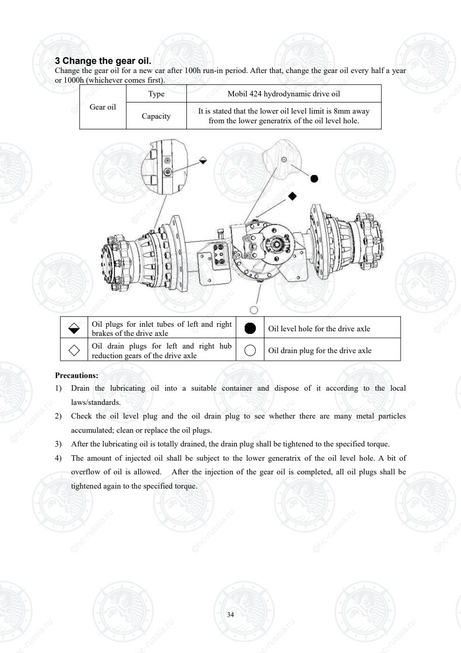
3 Change the gear oil.
Change the gear oil for a new car after 100h run-in period. After that, change the gear oil every half a year
or 1000h (whichever comes first).
Gear oil
Type Mobil 424 hydrodynamic drive oil
Capacity It is stated that the lower oil level limit is 8mm away
from the lower generatrix of the oil level hole.
Oil plugs for inlet tubes of left and right
brakes of the drive axle Oil level hole for the drive axle
Oil drain plugs for left and right hub
reduction gears of the drive axle Oil drain plug for the drive axle
Precautions:
1) Drain the lubricating oil into a suitable container and dispose of it according to the local
laws/standards.
2) Check the oil level plug and the oil drain plug to see whether there are many metal particles
accumulated; clean or replace the oil plugs.
3) After the lubricating oil is totally drained, the drain plug shall be tightened to the specified torque.
4) The amount of injected oil shall be subject to the lower generatrix of the oil level hole. A bit of
overflow of oil is allowed. After the injection of the gear oil is completed, all oil plugs shall be
tightened again to the specified torque.
Оригинальная страница: таблицы и схемы
Страница 40
35
4 Disassembly/assembly of the drive axle
When the drive axle is to be disassembled or assembled, it is needed to first remove it from the forklift.
Please follow the steps below:
Correctly hoist the drive axle by using appropriate equipment and then disconnect all lines connected to it.
Remove all bolts connected to the forklift; remove the drive axle from the forklift as a whole and then put it
on a flat surface.
Totally drain the gear oil in the drive axle.
Notice:
As this part is heavier, please use appropriate hoisting equipment and (or) lifting system for
operation.
Disassembly of the final drive
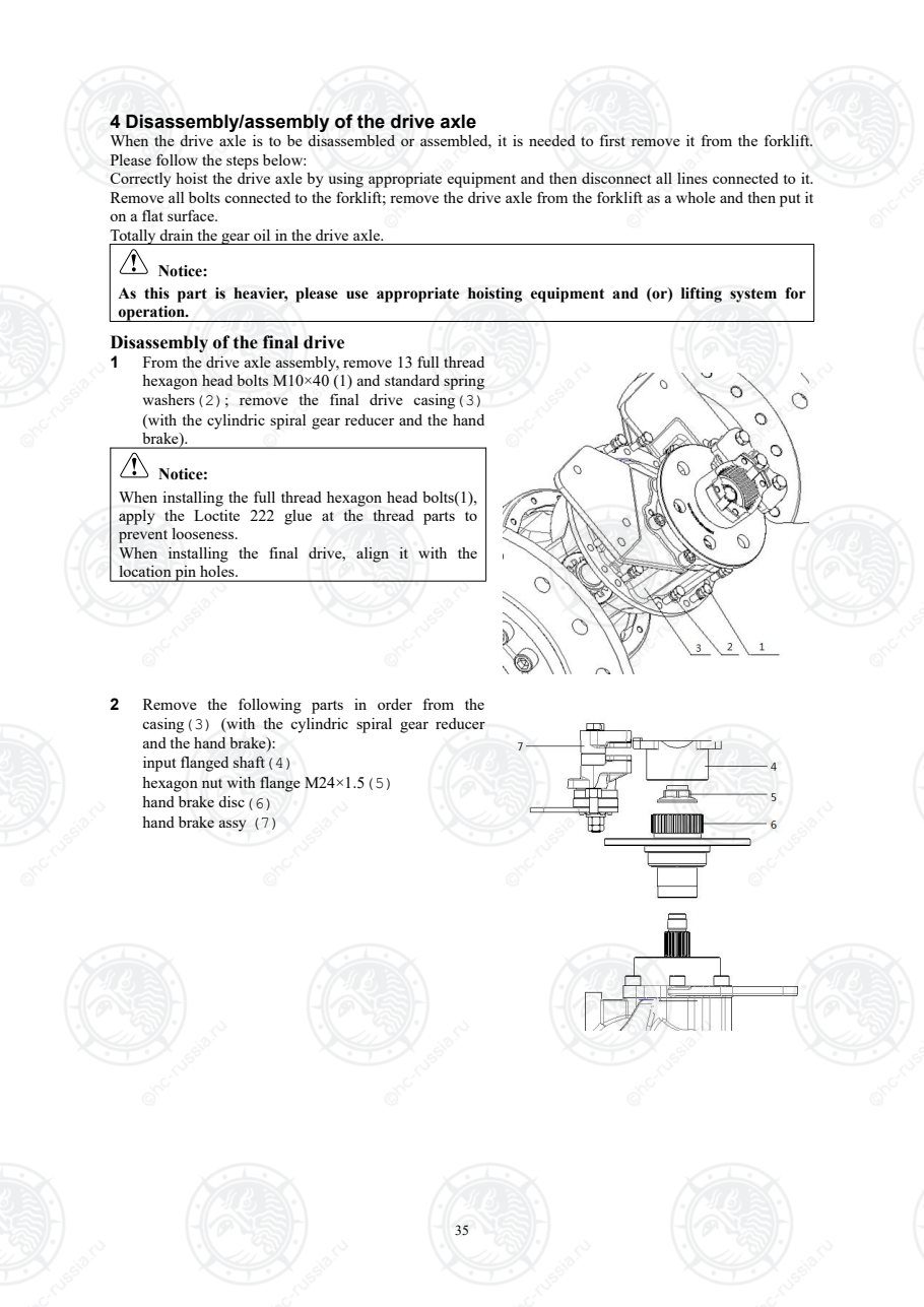
1 From the drive axle assembly, remove 13 full thread
hexagon head bolts M10×40 (1) and standard spring
washers(2); remove the final drive casing(3)
(with the cylindric spiral gear reducer and the hand
brake).
Notice:
When installing the full thread hexagon head bolts(1),
apply the Loctite 222 glue at the thread parts to
prevent looseness.
When installing the final drive, align it with the
location pin holes.
2 Remove the following parts in order from the
casing(3) (with the cylindric spiral gear reducer
and the hand brake):
input flanged shaft(4)
hexagon nut with flange M24×1.5(5)
hand brake disc(6)
hand brake assy (7)
Оригинальная страница: таблицы и схемы
Страница 41
36
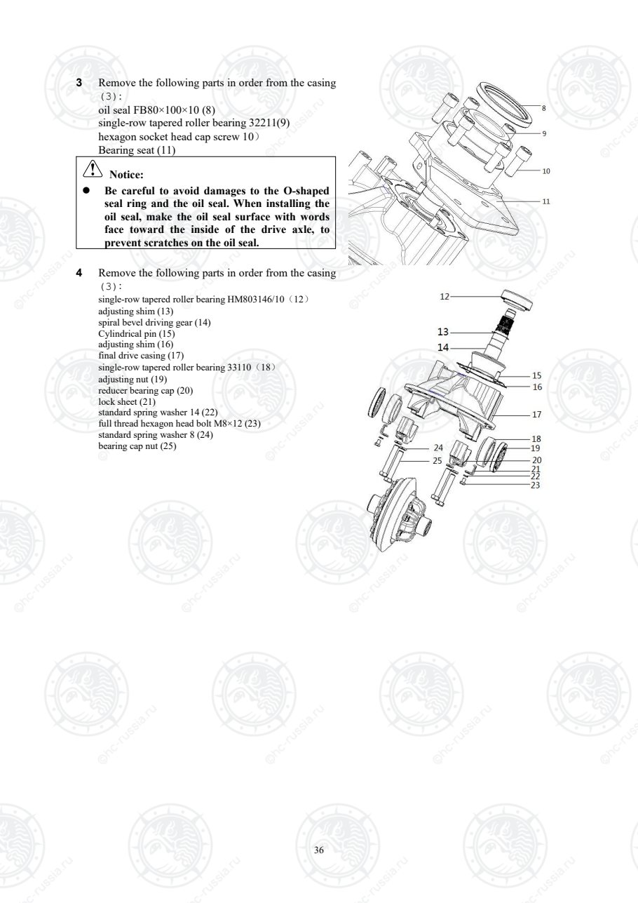
3 Remove the following parts in order from the casing
(3):
oil seal FB80×100×10 (8)
single-row tapered roller bearing 32211(9)
hexagon socket head cap screw 10)
Bearing seat (11)
Notice:
Be careful to avoid damages to the O-shaped
seal ring and the oil seal. When installing the
oil seal, make the oil seal surface with words
face toward the inside of the drive axle, to
prevent scratches on the oil seal.
4 Remove the following parts in order from the casing
(3):
single-row tapered roller bearing HM803146/10(12)
adjusting shim (13)
spiral bevel driving gear (14)
Cylindrical pin (15)
adjusting shim (16)
final drive casing (17)
single-row tapered roller bearing 33110(18)
adjusting nut (19)
reducer bearing cap (20)
lock sheet (21)
standard spring washer 14 (22)
full thread hexagon head bolt M8×12 (23)
standard spring washer 8 (24)
bearing cap nut (25)
Оригинальная страница: таблицы и схемы
Страница 42
37
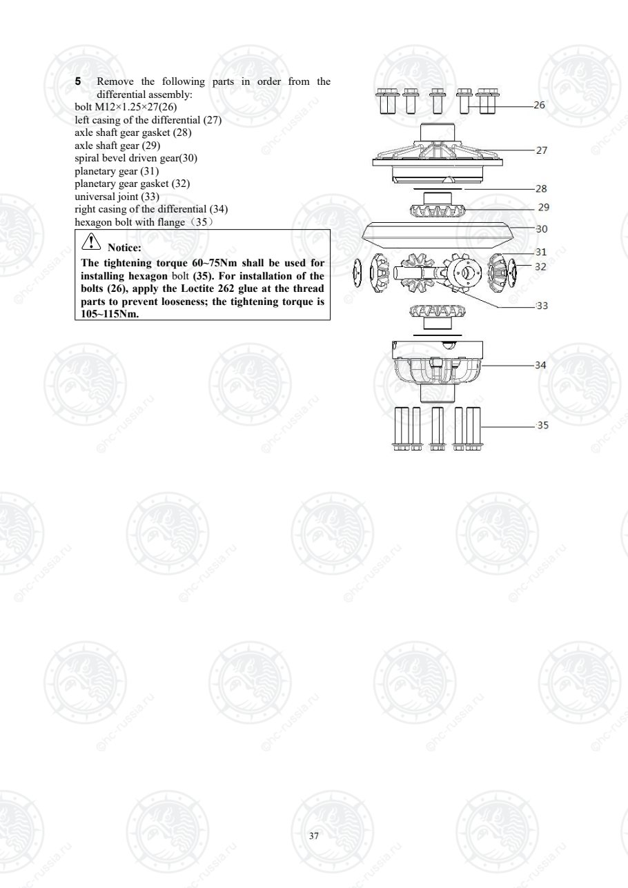
5 Remove the following parts in order from the
differential assembly:
bolt M12×1.25×27(26)
left casing of the differential (27)
axle shaft gear gasket (28)
axle shaft gear (29)
spiral bevel driven gear(30)
planetary gear (31)
planetary gear gasket (32)
universal joint (33)
right casing of the differential (34)
hexagon bolt with flange(35)
Notice:
The tightening torque 60~75Nm shall be used for
installing hexagon bolt (35). For installation of the
bolts (26), apply the Loctite 262 glue at the thread
parts to prevent looseness; the tightening torque is
105~115Nm.
Оригинальная страница: таблицы и схемы
Страница 43
38
Disassembly of the left/right hub reduction gears
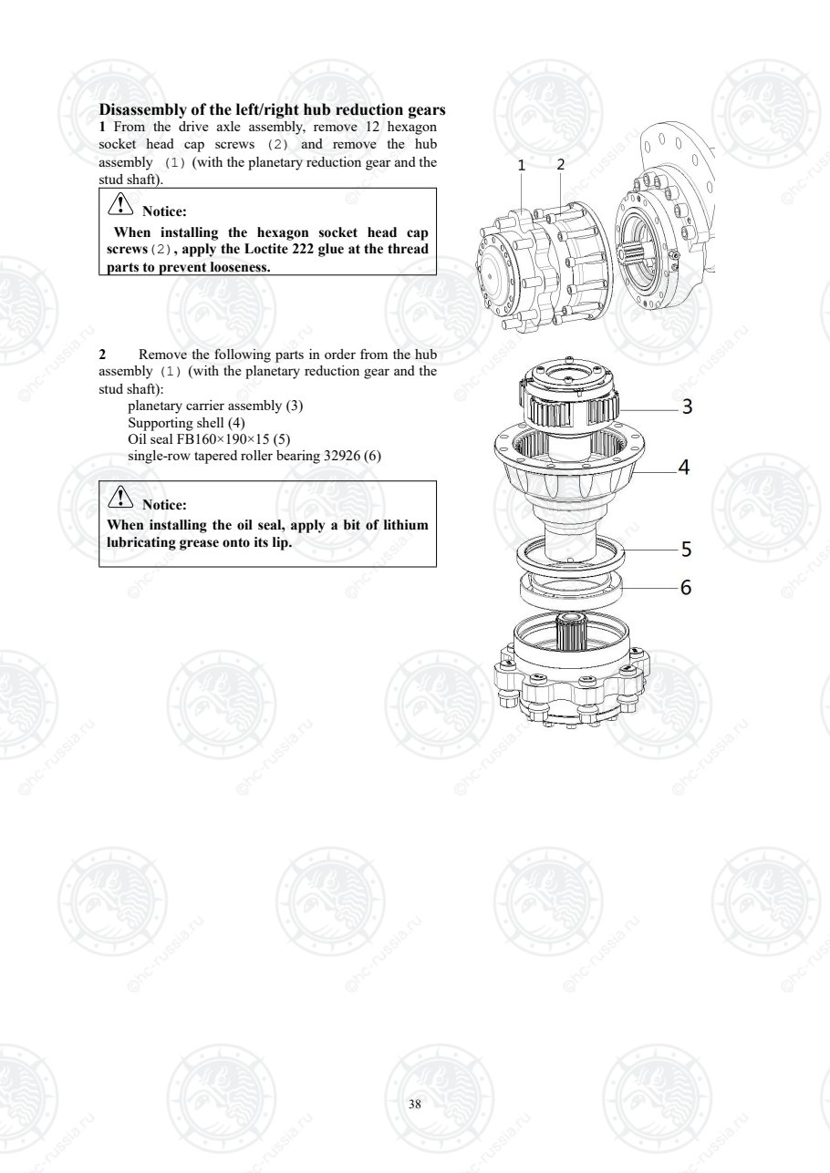
1 From the drive axle assembly, remove 12 hexagon
socket head cap screws (2) and remove the hub
assembly (1) (with the planetary reduction gear and the
stud shaft).
Notice:
When installing the hexagon socket head cap
screws(2), apply the Loctite 222 glue at the thread
parts to prevent looseness.
2 Remove the following parts in order from the hub
assembly (1) (with the planetary reduction gear and the
stud shaft):
planetary carrier assembly (3)
Supporting shell (4)
Oil seal FB160×190×15 (5)
single-row tapered roller bearing 32926 (6)
Notice:
When installing the oil seal, apply a bit of lithium
lubricating grease onto its lip.
Оригинальная страница: таблицы и схемы
Страница 44
39
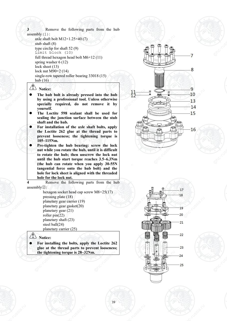
3 Remove the following parts from the hub
assembly(1):
axle shaft bolt M12×1.25×40 (7)
stub shaft (8)
type circlip for shaft 52 (9)
Limit block (10)
full thread hexagon head bolt M6×12 (11)
spring washer 6 (12)
lock sheet (13)
lock nut M90×2 (14)
single-row tapered roller bearing 33018 (15)
hub (16)
Notice:
The hub bolt is already pressed into the hub
by using a professional tool. Unless otherwise
specially required, do not remove it by
yourself.
The Loctite 598 sealant shall be used for
sealing the junction surface between the stub
shaft and the hub.
For installation of the axle shaft bolts, apply
the Loctite 262 glue at the thread parts to
prevent looseness; the tightening torque is
105~115Nm.
Pre-tighten the hub bearing: screw the lock
nut while you rotate the hub, until it is difficult
to rotate the hub; then unscrew the lock nut
until the hub start torque reaches 3.5~6.3Nm
(the hub can rotate when you apply 30-55N
tangential force onto the hub bolt) and the
hole for lock sheet is aligned with the threaded
hole for the lock nut.
4 Remove the following parts from the hub
assembly②:
hexagon socket head cap screw M8×25(17)
pressing plate (18)
planetary gear carrier (19)
planetary gear gasket(20)
planetary gear (21)
roller pin(22)
planetary shaft (23)
steel ball(24)
planetary carrier (25)
Notice:
For installing the bolts, apply the Loctite 262
glue at the thread parts to prevent looseness;
the tightening torque is 28~32Nm.
Оригинальная страница: таблицы и схемы
Страница 45
40
Disassembly of the brake part
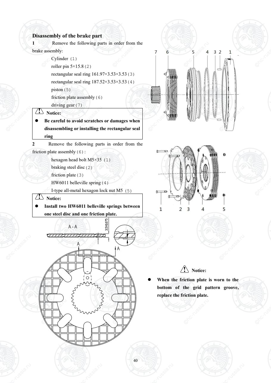
1 Remove the following parts in order from the
brake assembly:
Cylinder (1)
roller pin 5×15.8(2)
rectangular seal ring 161.97×3.53×3.53(3)
rectangular seal ring 187.52×3.53×3.53(4)
piston(5)
friction plate assembly(6)
driving gear(7)
Notice:
Be careful to avoid scratches or damages when
disassembling or installing the rectangular seal
ring
2 Remove the following parts in order from the
friction plate assembly(6):
hexagon head bolt M5×35 (1)
braking steel disc(2)
friction plate(3)
HW6011 belleville spring(4)
I-type all-metal hexagon lock nut M5 (5)
Notice:
Install two HW6011 belleville springs between
one steel disc and one friction plate.
Notice:
When the friction plate is worn to the
bottom of the grid pattern groove,
replace the friction plate.
Оригинальная страница: таблицы и схемы
Страница 46
41
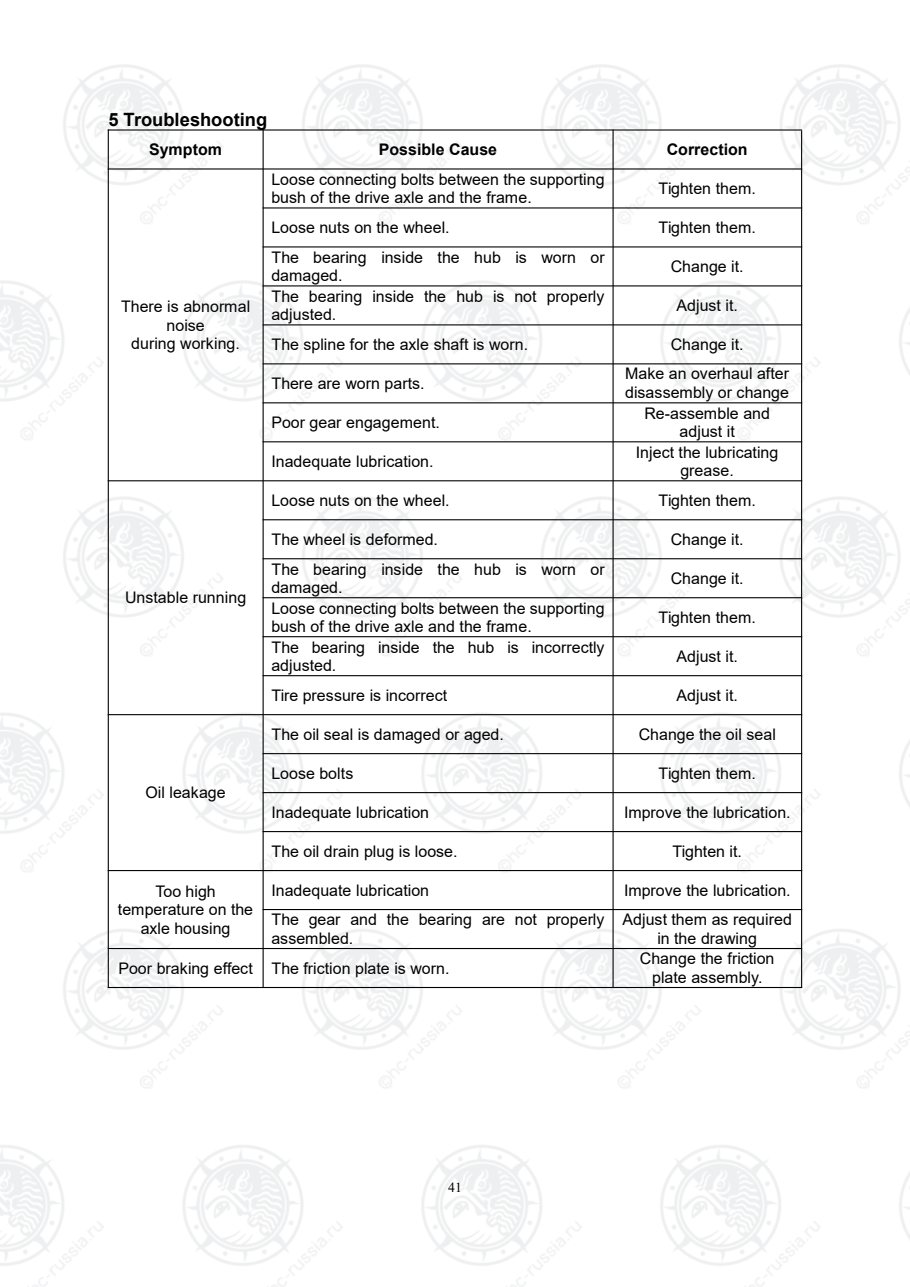
5 Troubleshooting
Symptom Possible Cause Correction
There is abnormal
noise
during working.
Loose connecting bolts between the supporting
bush of the drive axle and the frame. Tighten them.
Loose nuts on the wheel. Tighten them.
The bearing inside the hub is worn or
damaged. Change it.
The bearing inside the hub is not properly
adjusted. Adjust it.
The spline for the axle shaft is worn. Change it.
There are worn parts. Make an overhaul after
disassembly or change
parts.Poor gear engagement. Re-assemble and
adjust it
Inadequate lubrication. Inject the lubricating
grease.
Unstable running
Loose nuts on the wheel. Tighten them.
The wheel is deformed. Change it.
The bearing inside the hub is worn or
damaged. Change it.
Loose connecting bolts between the supporting
bush of the drive axle and the frame. Tighten them.
The bearing inside the hub is incorrectly
adjusted. Adjust it.
Tire pressure is incorrect Adjust it.
Oil leakage
The oil seal is damaged or aged. Change the oil seal
Loose bolts Tighten them.
Inadequate lubrication Improve the lubrication.
The oil drain plug is loose. Tighten it.
Too high
temperature on the
axle housing
Inadequate lubrication Improve the lubrication.
The gear and the bearing are not properly
assembled.
Adjust them as required
in the drawing
Poor braking effect The friction plate is worn. Change the friction
plate assembly.
Оригинальная страница: таблицы и схемы
Страница 47
42
Ⅲ Steering system
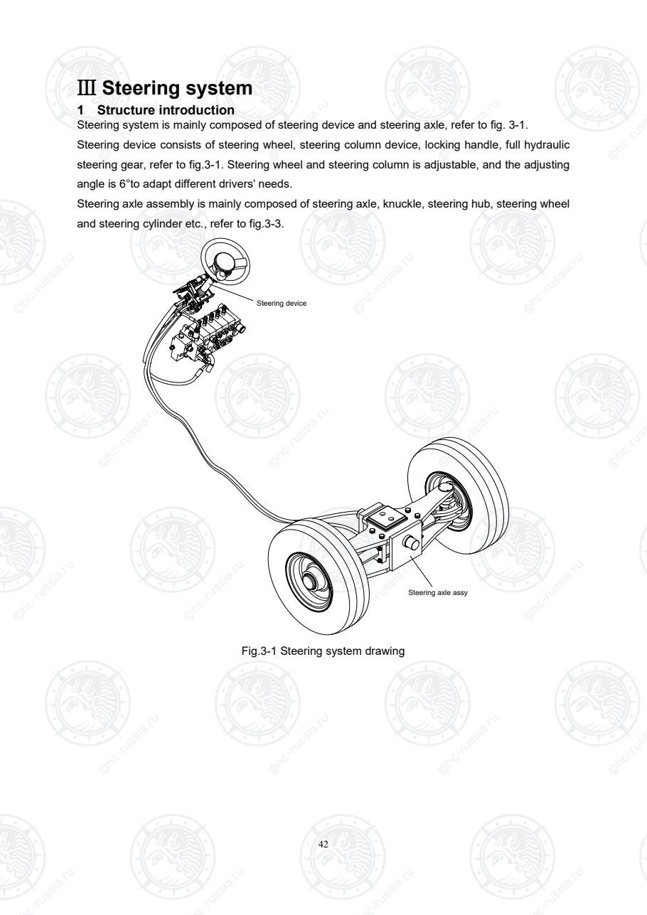
1 Structure introduction
Steering system is mainly composed of steering device and steering axle, refer to fig. 3-1.
Steering device consists of steering wheel, steering column device, locking handle, full hydraulic
steering gear, refer to fig.3-1. Steering wheel and steering column is adjustable, and the adjusting
angle is 6°to adapt different drivers’ needs.
Steering axle assembly is mainly composed of steering axle, knuckle, steering hub, steering wheel
and steering cylinder etc., refer to fig.3-3.
Steering axle assy
Steering device
Fig.3-1 Steering system drawing
Оригинальная страница: таблицы и схемы
Страница 48
43
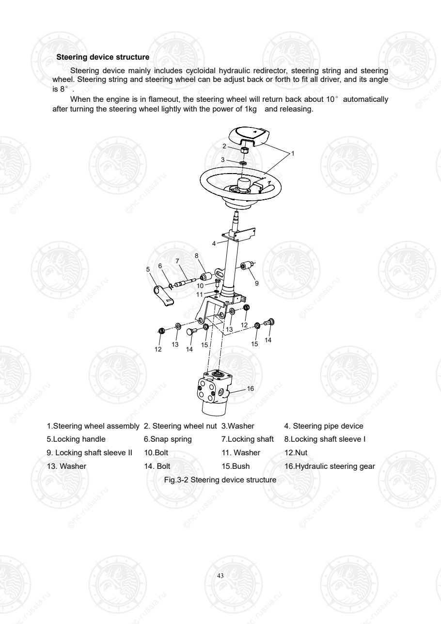
Steering device structure
Steering device mainly includes cycloidal hydraulic redirector, steering string and steering
wheel. Steering string and steering wheel can be adjust back or forth to fit all driver, and its angle
is 8°.
When the engine is in flameout, the steering wheel will return back about 10°automatically
after turning the steering wheel lightly with the power of 1kg and releasing.
12 13 14 15
1213
1415
16
3
8
765
4
910
11
2
1
1.Steering wheel assembly 2. Steering wheel nut 3.Washer 4. Steering pipe device
5.Locking handle 6.Snap spring 7.Locking shaft 8.Locking shaft sleeve I
9. Locking shaft sleeve II 10.Bolt 11. Washer 12.Nut
13. Washer 14. Bolt 15.Bush 16.Hydraulic steering gear
Fig.3-2 Steering device structure
Оригинальная страница: таблицы и схемы
Страница 49
44
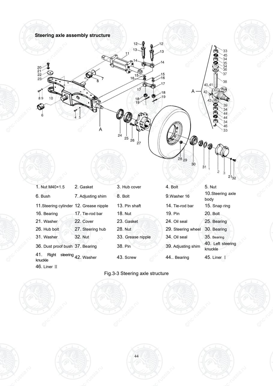
Steering axle assembly structure
1. Nut M40×1.5 2. Gasket 3. Hub cover 4. Bolt 5. Nut
6. Bush 7. Adjusting shim 8. Bolt 9.Washer 16 10.Steering axle
body
11.Steering cylinder 12. Grease nipple 13. Pin shaft 14. Tie-rod bar 15. Snap ring
16. Bearing 17. Tie-rod bar 18. Nut 19. Pin 20. Bolt
21. Washer 22. Cover 23. Gasket 24. Oil seal 25. Bearing
26. Hub bolt 27. Steering hub 28. Nut 29. Steering wheel 30. Bearing
31. Washer 32. Nut 33. Grease nipple 34. Oil seal 35. Bearing
36. Dust proof bush 37. Bearing 38. Pin 39. Adjusting shim 40. Left steering
knuckle
41. Right steering
knuckle 42. Washer 43. Screw 44.. Bearing 45. Liner Ⅰ
46. Liner Ⅱ
Fig.3-3 Steering axle structure
Оригинальная страница: таблицы и схемы
Страница 50
45
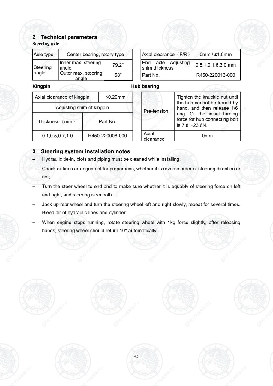
2 Technical parameters
Steering axle
Axle type Center bearing, rotary type Axial clearance(F/R) 0mm / ≤1.0mm
Steering
angle
Inner max. steering
angle 79.2° End axle Adjusting
shim thickness 0.5,1.0,1.6,3.0 mm
Outer max. steering
angle 58° Part No. R450-220013-000
Kingpin Hub bearing
Axial clearance of kingpin ≤0.20mm
Pre-tension
Tighten the knuckle nut until
the hub cannot be turned by
hand, and then release 1/6
ring. Or the initial turning
force for hub connecting bolt
is 7.8~23.6N.
Adjusting shim of kingpin
Thickness(mm) Part No.
0.1,0.5,0.7,1.0 R450-220008-000 Axial
clearance 0mm
3 Steering system installation notes
– Hydraulic tie-in, blots and piping must be cleaned while installing;
– Check oil lines arrangement for properness, whether it is reverse order of steering direction or
not;
– Turn the steer wheel to end and to make sure whether it is equably of steering force on left
and right, and steering is smooth.
– Jack up rear wheel and turn the steering wheel left and right slowly, repeat for several times.
Bleed air of hydraulic lines and cylinder.
– When engine stops running, rotate steering wheel with 1kg force slightly, after releasing
hands, steering wheel should return 10° automatically..
Оригинальная страница: таблицы и схемы
Страница 51
46
4 Fault diagnoses and corrections
condition Probable cause Corrective action
Failure to rotate
steering wheel
Damage or trouble of oil pump Replace
Priority valve(multi-way valve) is clogged or
damaged. Clean or replace
Damaged hose or connector, block lines Replace or clean
Laborious
operation for
steering
Steering overflow value pressure too low. Adjust pressure.
Air in oil lines. Exhaust air
Control oil pipe is blocked Clean or replace
Priority valve(multi-way valve) fault Check or replace
The steering fails to turn to its natural position,
broken lock spring or insufficient spring pressure Replace spring flat
Too much internal leakage in steering cylinder. Check piston for sealing
Abnormal noise
Oil is not sufficient in oil tank. Add oil.
Suction piping or filter clogged. Clean or replace.
Oil leakage Damaged guide sleeve sealing of steering
cylinder or hose or connector. Replace
5 Hydraulic steering gear
The hydraulic redirector is a resistance-insensitive steering gear, shown in Fig.7-2. The rotor
(9) and stator (10) are a pair of cycloidal needle gears (internally engaged), which act as a
metering servo valve in case of power steering. It is connected between the priority dividing valve
and the steering cylinder. The oil directed to or out of the steering cylinder must flow past the
metering servo valve. Therefore, this valve opens to supply oil flow, coming from the priority
dividing valve, to the steering cylinder n proportion to the angle the steering wheel is turned. The
rotary valve (valve spool 4and valve guide 11) is connected to coupling block (8) and is used to
distribute oil, making the output changed in synchronism with the angle of rotor.
When the steering wheel is not turning the valve spool (4) and the valve guide (11) are
situated in neutral position under the action of spring flat (5), and closes the connection to the
steering cylinder, by that time, oil returns to oil tank directly.
When the engine stops running, the pump does not supply oil, and the steering action will be
realized manually by turning the steering wheel to move valve spool (4), valve guide (11), coupling
block (2), and to actuate he rotor (9) to feed oil into steering cylinder, in this case, rotor (9) and
stator (10) act as a hand pump, making manual steering possible.
Оригинальная страница: таблицы и схемы
Страница 52
47
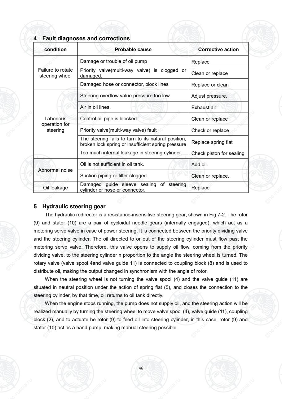
Fig.3-4 Cycloidal hydraulic redirector
1. Location limited string 2. Shaft 3. Valve body 4. Valve core 5. Flat spring
6. O-ring 7. Y-seal ring 8. Coupling block 9. Rotor 10.Stator
11. Valve guide
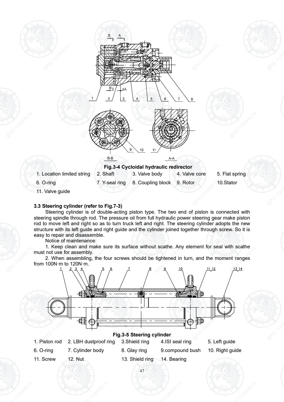
3.3 Steering cylinder (refer to Fig.7-3)
Steering cylinder is of double-acting piston type. The two end of piston is connected with
steering spindle through rod. The pressure oil from full hydraulic power steering gear make piston
rod to move left and right so as to turn truck left and right. The steering cylinder adopts the new
structure with its left guide and right guide and the cylinder joined together through screw. So it is
easy to repair and disassemble.
Notice of maintenance:
1. Keep clean and make sure its surface without scathe. Any element for seal with scathe
must not use for assembly.
2. When assembling, the four screws should be tightened in turn, and the moment ranges
from 100N·m to 120N·m.
Fig.3-5 Steering cylinder
1. Piston rod 2. LBH dustproof ring 3.Shield ring 4.ISI seal ring 5. Left guide
6. O-ring 7. Cylinder body 8. Glay ring 9.compound bush 10. Right guide
11. Screw 12. Nut 13. Shield ring 14. Bearing
Оригинальная страница: таблицы и схемы
Страница 53
48
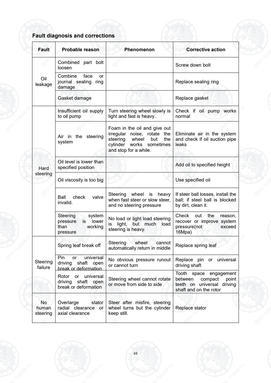
Fault diagnosis and corrections
Fault Probable reason Phenomenon Corrective action
Oil
leakage
Combined part bolt
loosen Screw down bolt
Combine face or
journal sealing ring
damage
Replace sealing ring
Gasket damage Replace gasket
Hard
steering
Insufficient oil supply
to oil pump
Turn steering wheel slowly is
light and fast is heavy..
Check if oil pump works
normal
Air in the steering
system
Foam in the oil and give out
irregular noise, rotate the
steering wheel but the
cylinder works sometimes
and stop for a while.
Eliminate air in the system
and check if oil suction pipe
leaks
Oil level is lower than
specified position Add oil to specified height
Oil viscosity is too big Use specified oil
Ball check valve
invalid.
Steering wheel is heavy
when fast steer or slow steer,
and no steering pressure
If steer ball losses, install the
ball; if steel ball is blocked
by dirt, clean it.
Steering system
pressure is lower
than working
pressure
No load or light load steering
is light, but much load
steering is heavy.
Check out the reason,
recover or improve system
pressure(not exceed
16Mpa)
Steering
failure
Spring leaf break off Steering wheel cannot
automatically return in middle Replace spring leaf
Pin or universal
driving shaft open
break or deformation
No obvious pressure runout
or cannot turn
Replace pin or universal
driving shaft
Rotor or universal
driving shaft open
break or deformation
Steering wheel cannot rotate
or move from side to side
Tooth space engagement
between compact point
teeth on universal driving
shaft and on the rotor
No
human
steering
Overlarge stator
radial clearance or
axial clearance
Steer after misfire, steering
wheel turns but the cylinder
keep still.
Replace stator
Оригинальная страница: таблицы и схемы
Страница 54
49
6 Steering axle
6.1 Dismantle and assemble
Hub dismantle
– Jack-up the forklift and support with
blocks;
– Dismantle wheel assembly(29);
– Dismantle hub cover(34);
– Dismantle knuckle locknut, thrust washer
and adjusting nut;
– Pull out hub assembly;
– Dismantle inner ring of the bearing
Caution
Do not drop taper bearing.
Be caution not damage the seal
element.
Steering king pin and knuckle
– Dismantle nut(18) in the joint of knuckle
and draw bar device, disassemble draw
bar device;
– Loose the fixed screw(47);
– Dismantle oil cup of steering king pin;
(37);
– Dismantle steering king pin(42);
Caution
Push steering king pin to avoid drop.
– Take down the whole set of knuckle
(including thrust bearing, dustproof shell,
shim)
Inspect:
– Replace knuckle if cracked;
– Replace bearing if its rollers or roller
surfaces are rusted or nicked;
– Replace needle bearing if it damaged;
– Replace thrust bearing and dust cap if
they damaged.
Installation:
To install, reverse the order of removal.
Careful observes the following:
– Always insert kingpin from lower side;
– Install thrust bearing, set the tighten-ring
below the support and loosen-ring. Adjust
axial clearance to specification with shims.
Axial clearance is less than 0.2mm.
Caution
Thrust ball bearing is installed on
the upper knuckle, and the adjusting
shim is installed on the down
knuckle.
– Apply grease between inner dust proof,
loosen-ring, and tighten-ring.
Оригинальная страница: таблицы и схемы
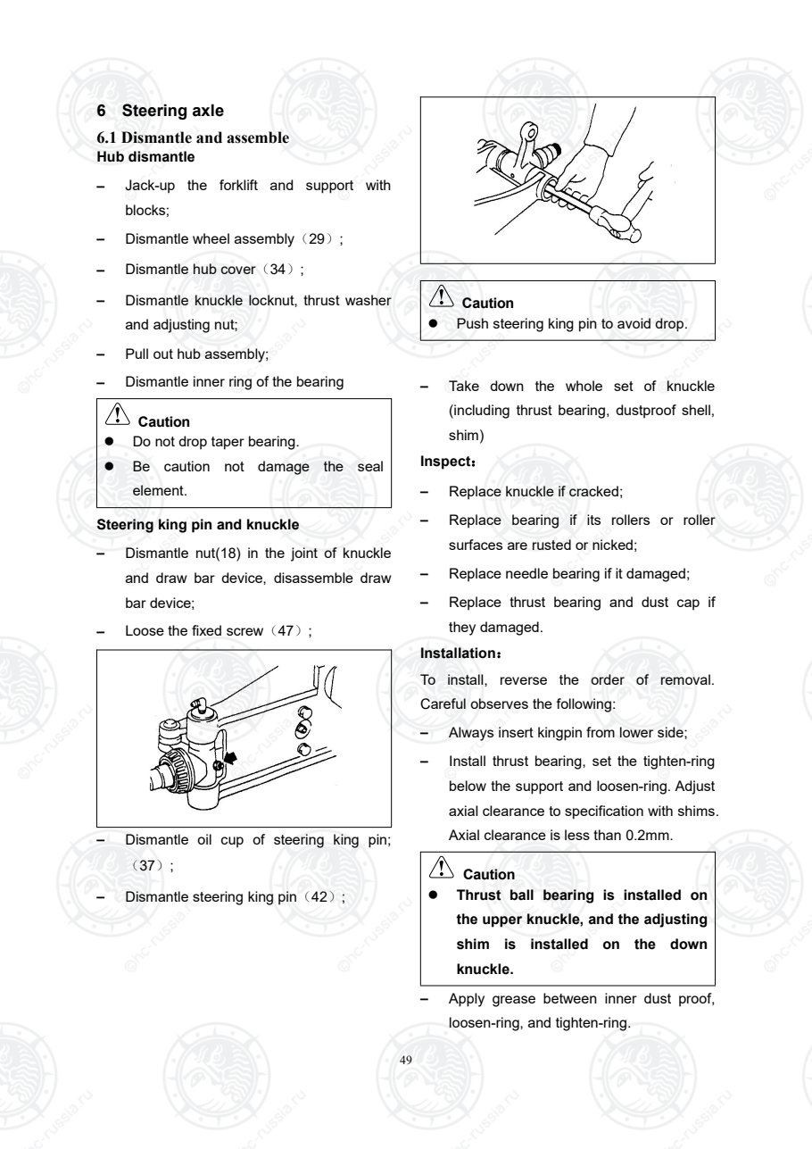
Страница 55
50
– Do not apply grease to the of needle
bearing outer ring and knuckle faying
surface
– Apple grease to roller of roller bearing and
ball of thrust bearing;
– Apply sufficient grease into the oil cup.
Hub bearing installation and adjustment
explanation
– Apply rust preventive oil on contact area
of nut (32) and bearing (30);
– Slowly rotate hub(27) with one hand.
Tighten locknut with the other hand until it
is hard to rotate steering hub(27), and
then rotate the nut(32) about 60°in
reverse direction;
– Rotate steering hub(27) 2~3 cycles, and
rotate the bearing roller in place;
– Rotate the steering hub(27) with one hand,
and screw down the nut(32) with the other
hand, rotation initial torque: T=0.88 ~
2.65N.m.
– Place the protruding part of washer (31)
into the knuckle groove, adjust the outer
nut (32), align the notch at the outer
protruding part of washer (31), then put
the protruding part of washer (31) into the
nut notch.
– Rotate the steering hub(27) for 2 cycles,
measure the rotation initial force( 7.8~
23.6N)and if axial clearance(no clearance
in axial direction) meets stand, and adjust
if necessary.
Оригинальная страница: таблицы и схемы
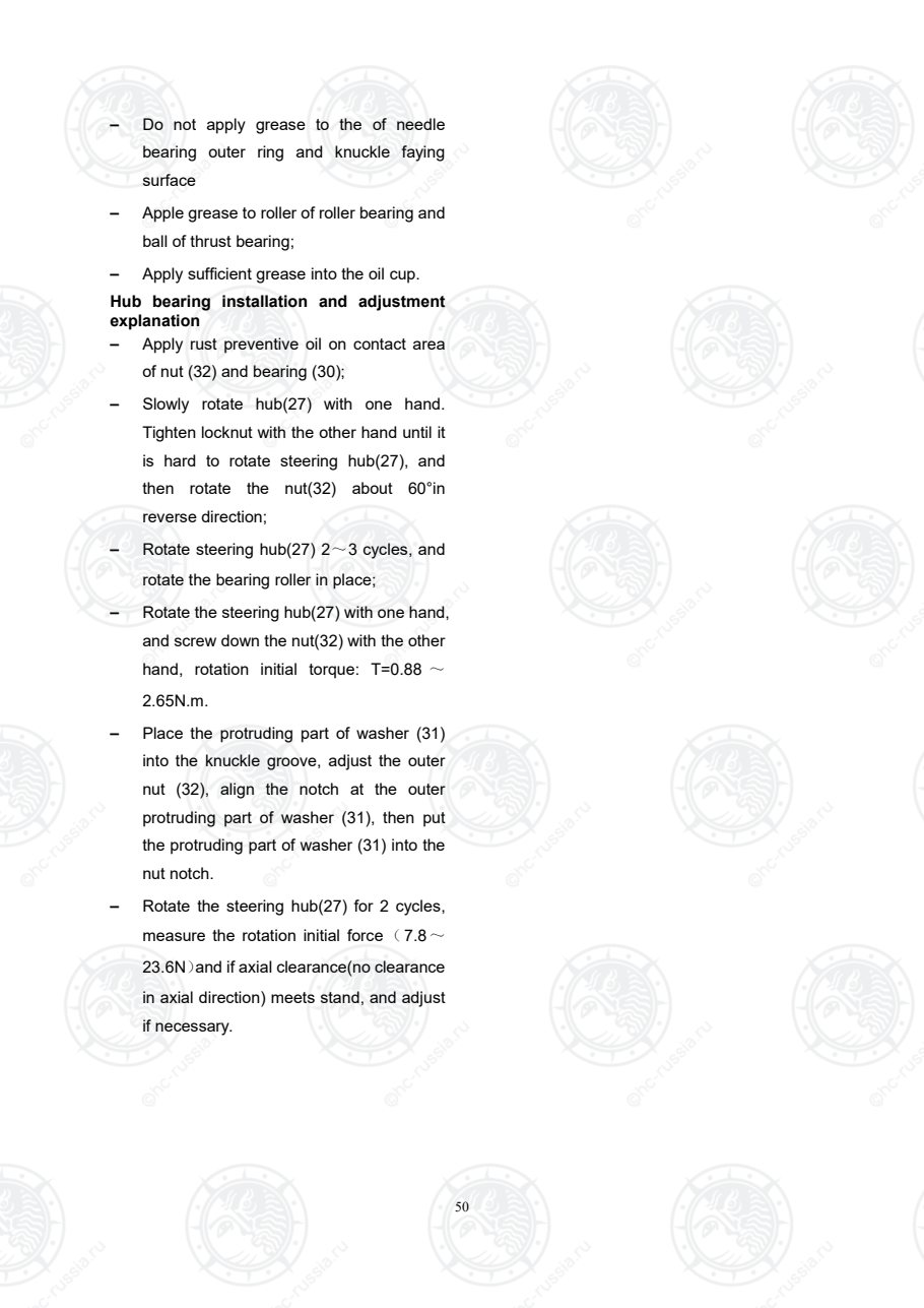
Страница 56
51
6.2 Fault diagnoses and corrections
condition Probable cause Corrective action
Unstable travel
Wheel nuts loosens Tighten
Wheel bearing exceeds adjusting
scope Adjust
Incorrect installation of end axle
adjusting shim Adjust
Steering system failure Refer to the “steering system trouble
diagnoses and corrections”
Noise
Insufficient lubrication Apply and fill lithium base grease
Bolt or nut loosens Tighten
Incorrect adjustment of end axle
adjusting shim Adjust
Knuckle bearing on two ends of
connecting rod damaged Replace
Steering axle
A:Insert proper 0.1mm gasket between 2 thick gasket to make axial clearance less than 0.2mm.
Tightening torque:
N·m
Tightening torque:
N·m
1. Nut 363-490 2. Bolt M6×10 3.7-5
3 screw 25-35 4. Bolt M16×1.5×45 193-257
7 Steering cylinder
Steering cylinder is of double-acting piston type. The two end of piston is connected with
knuckle through rod. The pressure oil from hydraulic steering gear makes piston rod to move
Оригинальная страница: таблицы и схемы
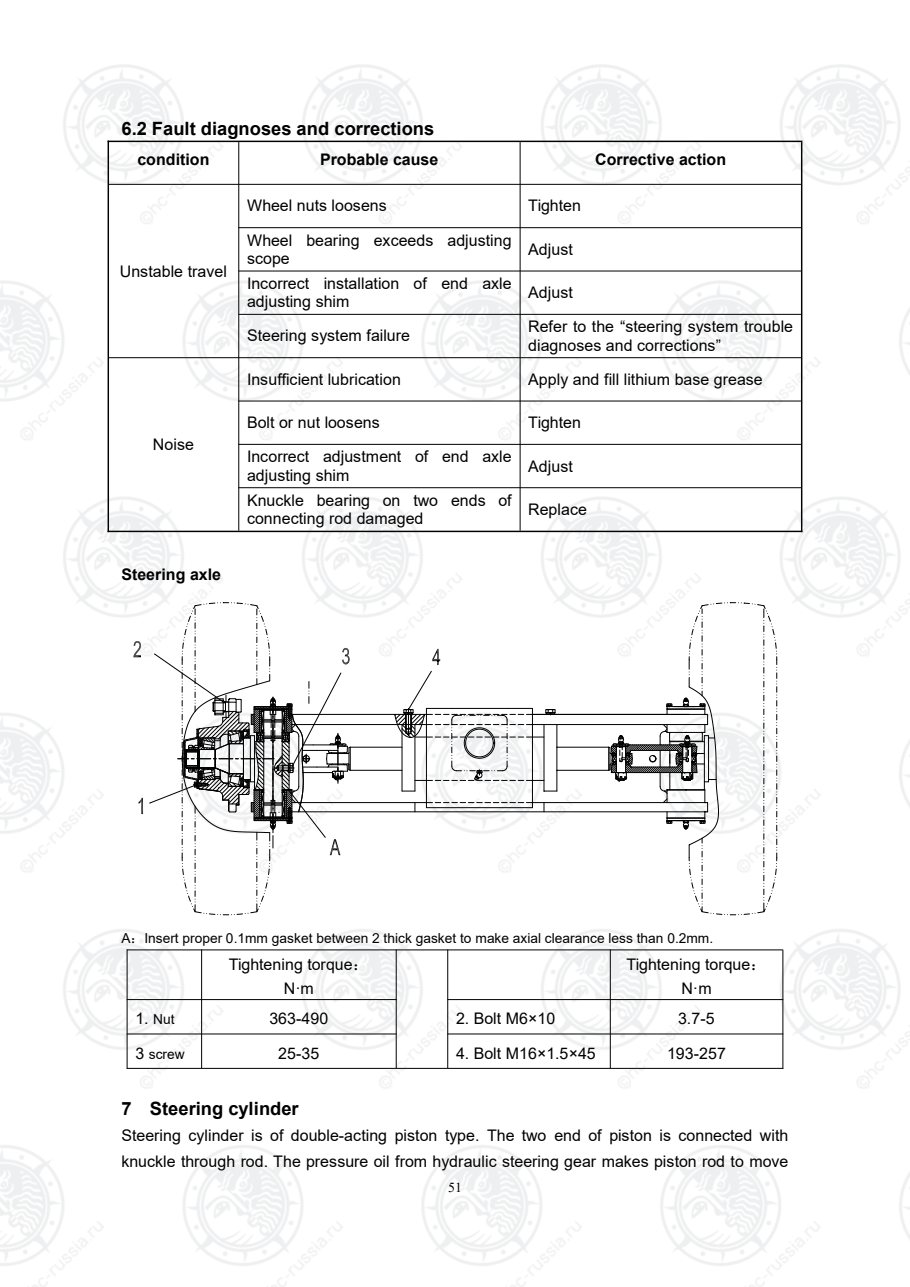
Страница 57
52
left and right so as to turn truck left and right. Refer to 3-6.
1.LBH Dust ring 2.Guard circle 3.ISI Sealing ring 4. Composite bush 5.Right guide sleeve
6.O-ring 7.Cylinder barrel 8. Glyd ring 9.Left guide sleeve 10.Piston rod
11.Bearing 12.Check ring 13.Nut 14.Screw
Fig.3-6 Steering cylinder structure
Disassembly procedures:
– Loosen nut(13), and remove screw(14);
– Dismantle left guide sleeve(9) and right two sides of guide sleeve(6);
– Dismantle LBH dust ring(1), guard circle(2), ISI sealing ring(3), composite bush(4).
O-ring(6) sequently;
– Dismantle piston rod(10) and Glyd ring(8).
– Check: replace if component damaged.
To install, reverse removal procedure.
Attentions to dismantle steering cylinder:
– Lubricate each part with clean hydraulic oil.
– Prevent dust and oil coming into the cylinder.
– Avoid scraping on cylinder mouth, inlet and outlet.
– ISI sealing ring lip is inward; LBH dust ring inlet is outward.
– Do not damage O-ring on the outer ring when installing.
– Be careful to centering, push the guide sleeve into cylinder barrel, avoid to damage O-ring
on the outer ring and sealing ring on inner ring.
– Apply the same brand grease with working oil between sealing ring.
Оригинальная страница: таблицы и схемы
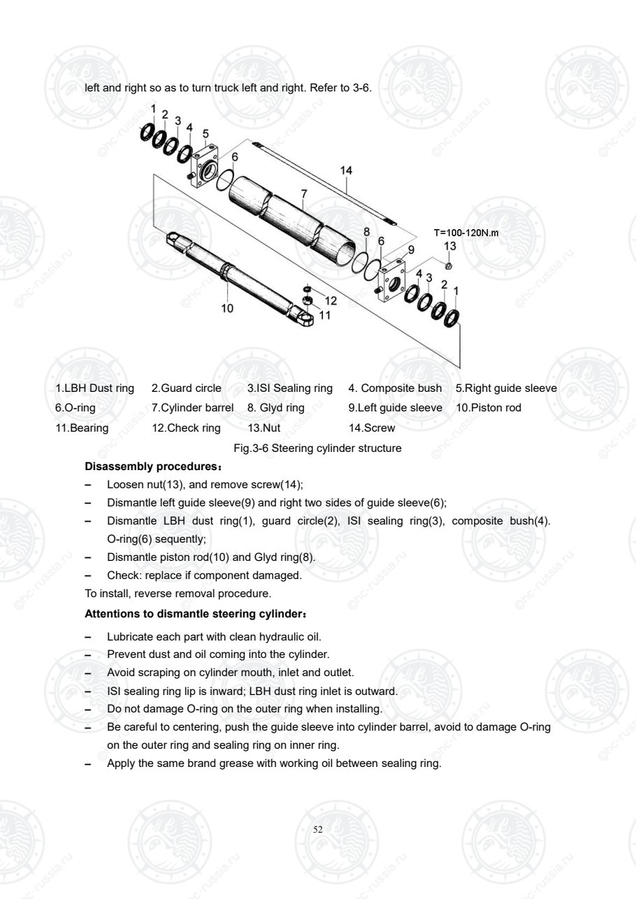
Страница 58
53
Ⅳ.Brake system
1 Summary
Brake system is composed of service brake system and parking brake system. Service brake
is front dual wheels vacuum booster or hydraulic boosting brake, park brake is Mechanical
pull-type brake, both woks on the shoe brakes which are installed on left and right front wheels.
Refer to fig. 4-1 or fig. 4-2.
Service brake realizes truck braking through foot steping and vacuum booster or hydraulic
boosting. This mechanism is mainly composed of brake inching bracket, brake inching pedal
mechanism, vacuum booster or hydraulic boosted braking assembly, brake line, brake oiler,
left/right shoe brake etc..
Hydraulic boosting brake assembly is composed by the joint of hydraulic boosted brake and
brake master cylinder, makes foot stepping easier and comfort, thus reduce operater’s fatigue.
Even in the event that the hydraulic boosting is invalid, it can use hydraulic braking to brake.
Parking brake mechanism is mainly composed of parking brake, left/right brake cable and
brake etc.
Brake owns hydraulic drive and automatic mechanism.
Use foot brake when to brake the truck during travelling. Hand brake is only used for daily
truck parking. It is prohibited to use hand brake as foot brake. If foot brake malfunctions during
travelling, use hand brake for emergency braking.
5
11
6 8
1
2 3
7
9
10
4
Fig.4-1 Brake system(China engine)
Оригинальная страница: таблицы и схемы
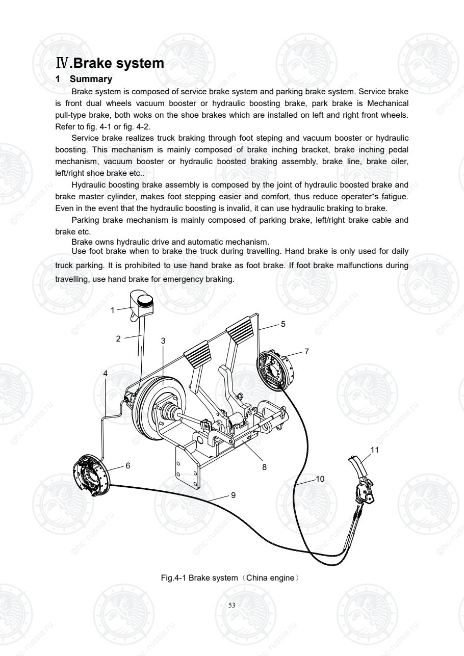
Страница 59
54
1. Brake oiler 2. Rubber hose 3. vacuum booster 4. Left brake pipe 5. Right brake pipe
6. Left brake 7. Right brake 8. Pedal assy 9. Left brake cable assy
10. Right brake cable assy 11. Parking brake
116
1
2
9
10
4
3
7
5
8
Fig.4-2 Brake system(Imported engine)
1. Brake oiler 2. Rubber hose 3. Hydraulic booster brake master pump 4. Left brake pipe
5. Right brake pipe 6. Left brake 7. Right brake 8. Pedal assy
9. Left brake cable assy 10. Right brake cable assy
11. Parking brake
2 Data
Brake master cylinder diameter mm 22″
Piston stroke mm 35
Vacuum booster
Membrane diameter Inch 8
Power ratio 4±0.15
Оригинальная страница: таблицы и схемы
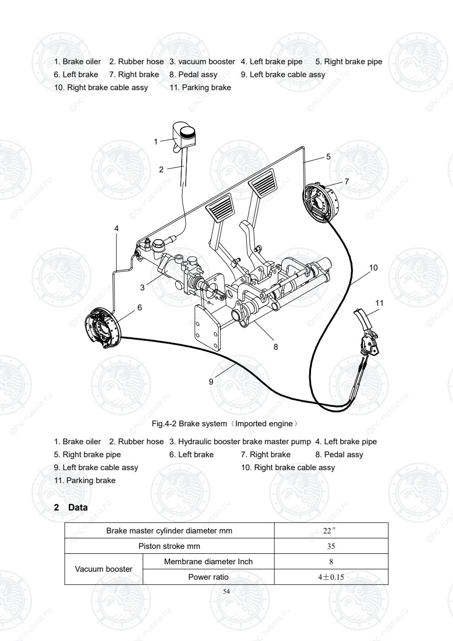
Страница 60
55
Brake
Type Oil pressure, internal expanding
front-wheel mechanical brake
Clearance between friction plate and drum
brake 0.4~0.6 mm
Wear limit of friction plate(to the rivet head) Larger than 0.5 mm
Parking brake Travel
Less than 80 mm
(With 147N tension force, at hand brake
handle)
Оригинальная страница: таблицы и схемы
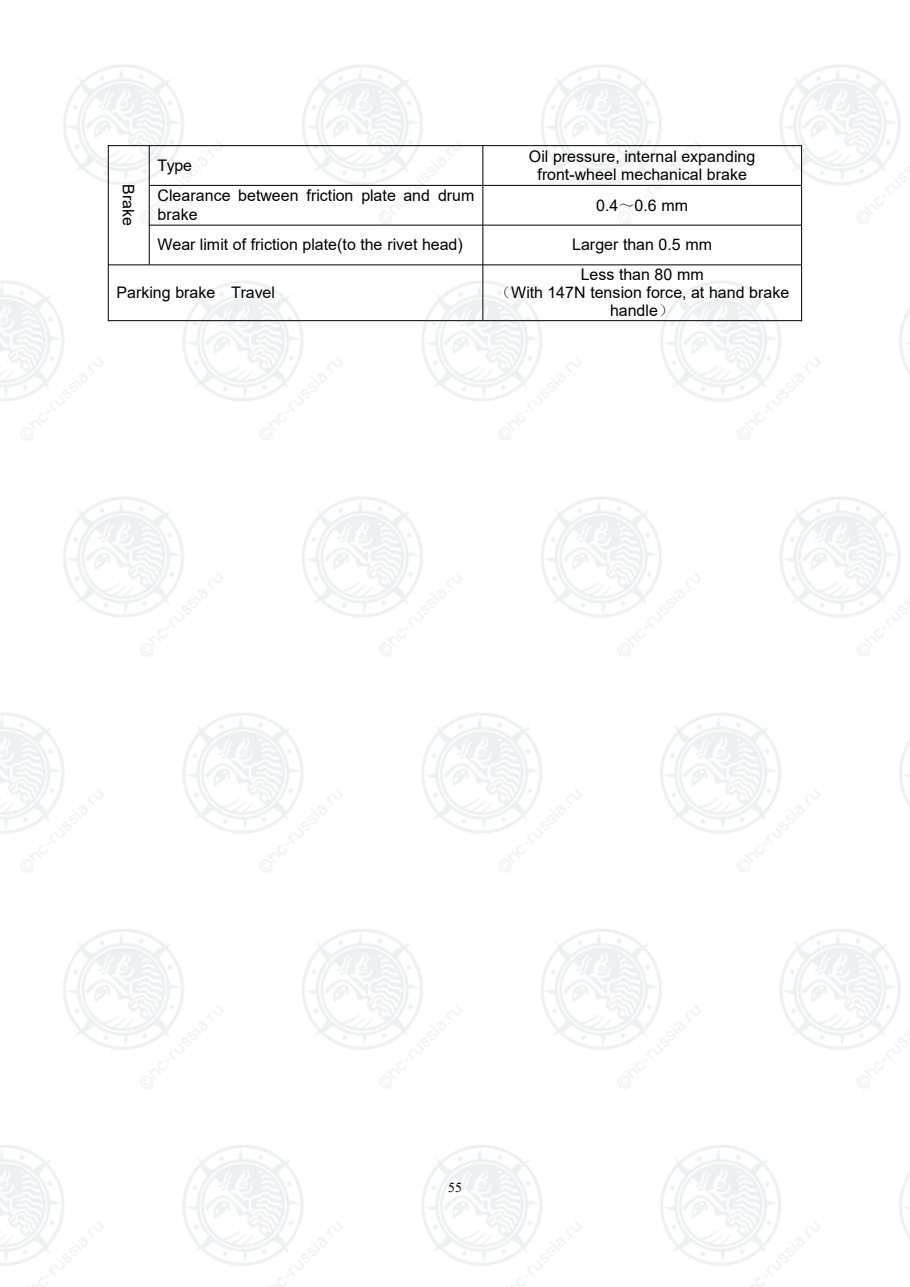
Страница 61
56
3 Brake inching pedal adjustment
Brake pedal adjustment:
– Adjust brake pedal stop bolt at A, make the pedal pad point P 145±5mm from the front base
plate and screw down the bolt nut.
– Adjust Brake Pump push rod length, and make the spare travel of the point P to point Q is 5~
15mm(just as1~3mm spare travel of push rod) , and lock the nut;
– When step the brake pedal 10 ~ 20mm gradually, the brake light switch is completely
connected, and release the foot to this state, brake light switch should disconnect.
Inching pedal adjustment:
– Adjust inching pedal stop bolt at C, make the pedal pad point P 145±5mm from the front base
plate and screw down the bolt nut.
– After adjusting the brake pedal, adjust the bolt at B and make the joint clearance between
inching pedal and brake pedal 0 mm, then tighten.
Fig.4-2 Brake inching pedal adjustment
Оригинальная страница: таблицы и схемы
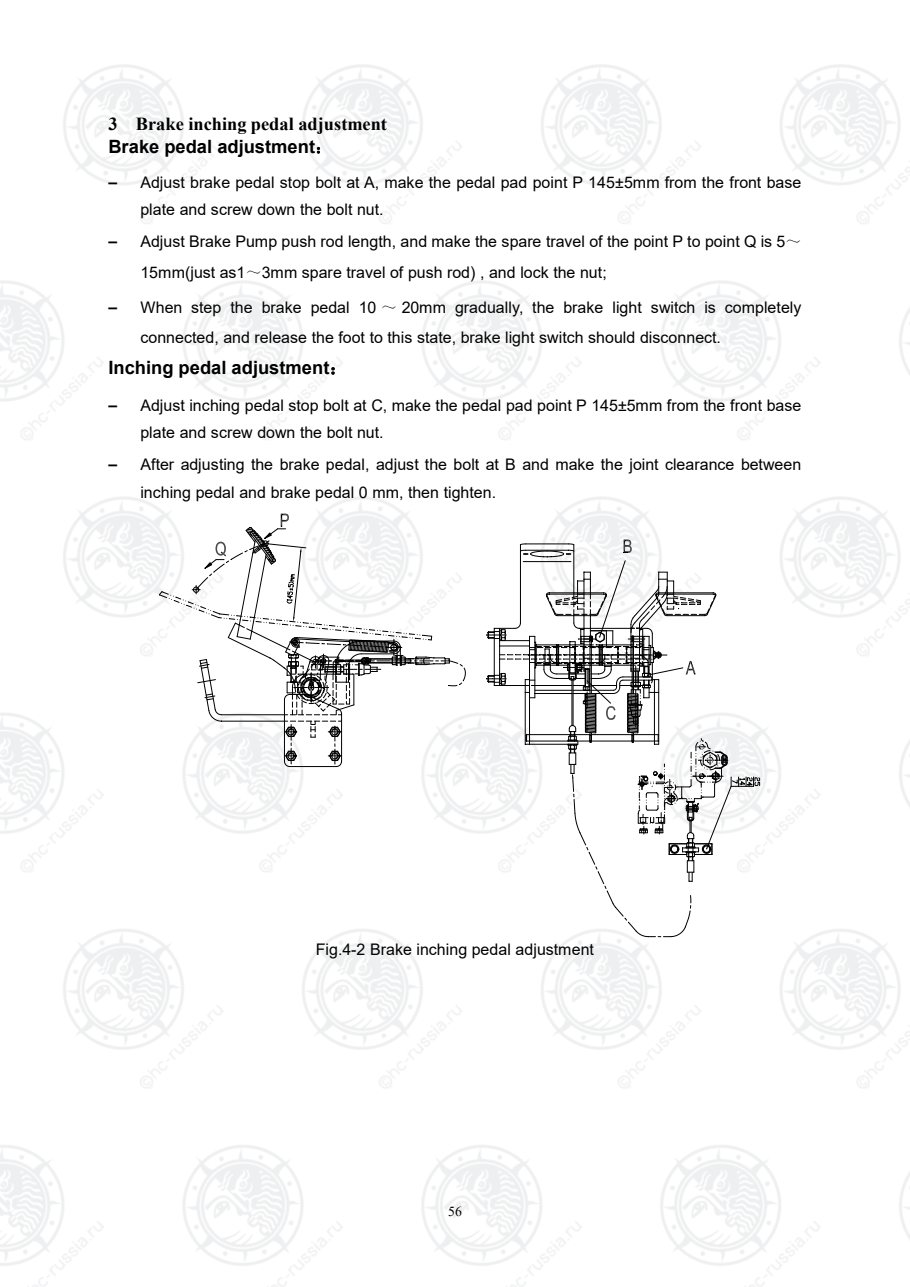
Страница 62
57
4 Parking brake adjustment
When it is found out that the free travel of parking brake handle is too large or brake effect is worse
after it is used for some time, please adjust it in time. Adjusting way is as follows:
– Before adjusting parking brake, check and adjust the shoe brakes on both sides of driving
wheel;
– Tighten nut B;
– Adjust nut A until handle force(P on Q direction) is 15~20kg when locking handle.
– Release pull rod of parking brake, and make sure wheel brake is completely released.
Note: Apply proper lithium base grease to guide rail, and keep applying frequently.
A
C
B
P
Q
Fig.4-3 Parking brake adjustment
Оригинальная страница: таблицы и схемы
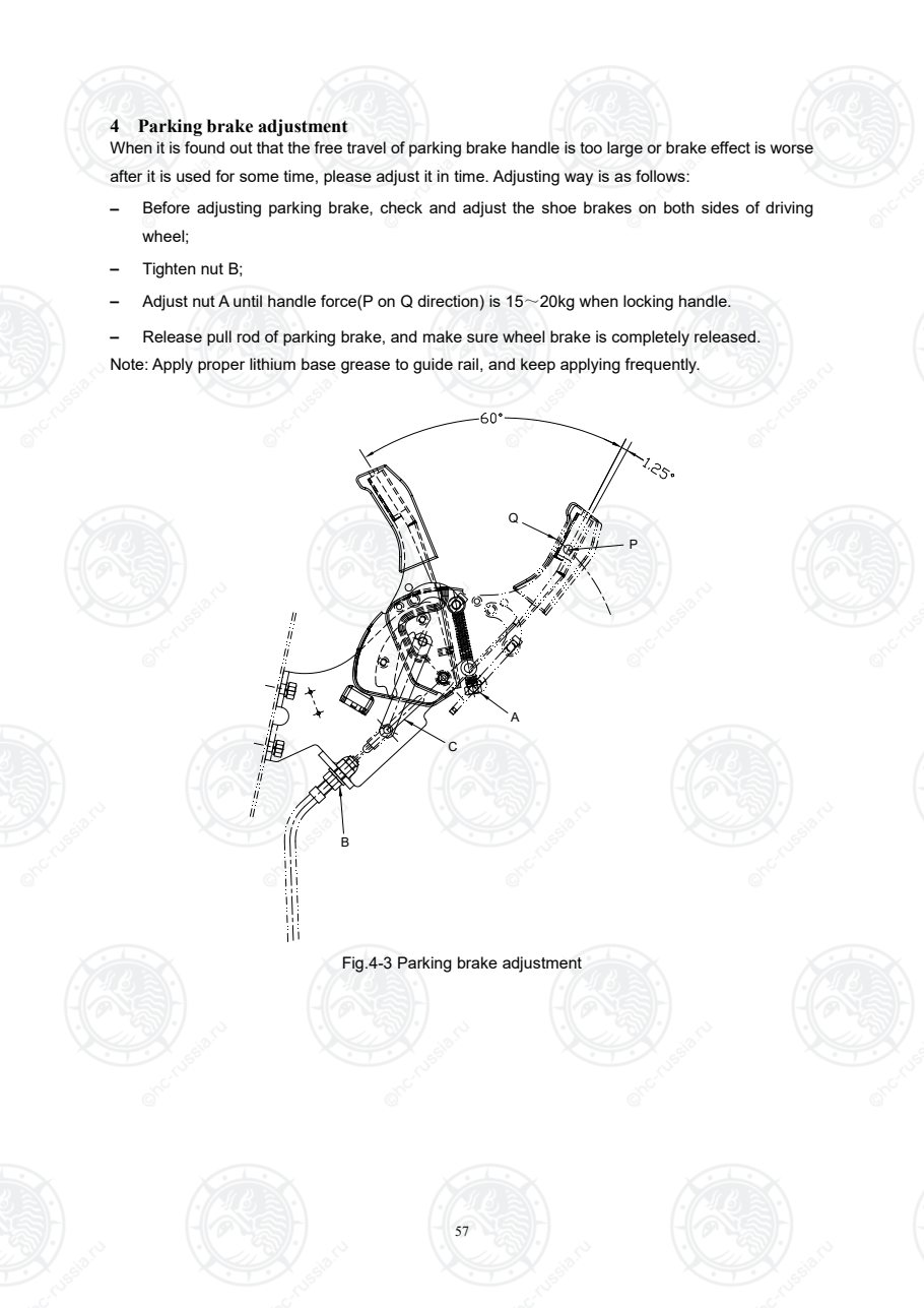
Страница 63
58
5 Brake
Adopted shoe brake is mainly composed of brake pad, brake shoe, brake cylinder and brake pad
adjusting mechanism.
When brake connects with drive axle, according to marks (left, right) on brake, bleeder screw is on the
slight upper, oil line should be cleaned before connecting.
When brake shoe does not work and lies in original position, there should be proper clearance
between friction plate and drum brake, and adjust the brake clearance to 0.25~0.5mm. Adjust
clearance in time after friction plate wears. If friction plate wears severely, (distance between rivet
head and friction plate is less than 0.5mm) replace it in pairs.
1 2 3 4 5 6 7 8 9
10
11
12
13
14
15
16
17 18
192032
21222324252627
2829
31
30
33
34
35
1.Housing 2.Bolt 3.Spring washer 4. Brake bottom plate
5.Brake cylinder 6. Brake shoe with
friction plate assembly 7.Return spring pin 8.Pin
9.Pin 10. Upper pull rod 11.Return spring 12.Rocker pin
13.Rocker 14.Cotter pin 15.Spring riveting
device 16.Torsional spring pin
17. Lower tension
spring 18.Pawl 19. Torsional spring 20.Adjuster assembly
21 Pressure spring
pedestal 22. Pressure spring 23. Pressure spring
pull rod 24.Check ring
25. Resilient pad 26.Bush 27.Hand brake
pushrod 28.Pushrod pin
29. Pull rod pin 30. Hand brake lever 31.Pin 32.Hand brake cable
33. Spring washer 34.Bolt 35.Rubber plug
Fig.4-4 Brake
Оригинальная страница: таблицы и схемы
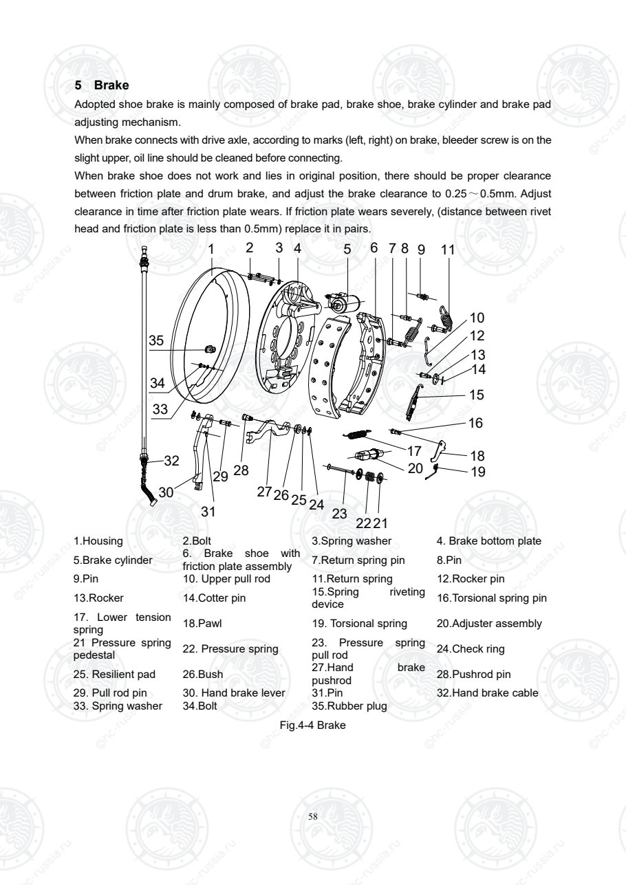
Страница 64
59
Replace brake shoe
– Place the forklift truck on level concrete.
– Start engine and raise forks about 100mm.
– Place chocks behind rear wheels to prevent movement of forklift truck.
– Loosen wheel nuts two or three turns each.
– Tilt mast fully backward, and place a wooden block under each side of outer mast.
Warning
Do not allow wooden blocks to touch
front tires.
– Tilt mast forward until front tires are raised from ground.
Warning
Do not unscrew the wheel nut before
the wheel rise from the ground.
– Support forklift truck by putting additional wooden blocks under each side of front-end frame.
– Stop engine.
– Remove wheel tire nuts and brake drum. Remove axle shaft, lock nut, and lock sheet.
– Remove wheel hub and brake drum.
– Replace brake shoes with new ones.
– Reinstall hub, brake drum, locknut and lock sheet. Adjust bearing clearance.
– Adjust shoe to drum clearance: rotate wheel counterclockwise and at the time press down
brake pedal several times.
– Take out every padding block:take out according to reverse procedures when inserting.
– Make sure no person or obstacle is around forklift, then operate forklift in reverse at 2 km/h to
3 km/h, set foot on brake pedal 2~3 times.
Оригинальная страница: таблицы и схемы
Страница 65
60
6. Vacuum booster(Truck with Chinese engine)
1. To use foot brake, when depressing the brake pedal, the vacuum booster pushrod is pushed by
pushrod directly, brake master cylinder pushrod power is increased due to the vacuum booster,
and then brake master cylinder main piston is pushed to get the master cylinder brake fluid into the
right brake cylinder and push the brake cylinder piston, thus the brake shoe is pressed on the
brake drum and the wheel is braked.
Fig.8-1 Working principle of vacuum booster
Fig.8-2 Vacuum booster structure
Brake pedal free travel is 5mm-15mm, please check when the brake pedal is too low:
(1) If oil leakage in the pipe;
(2) If air in the pipe;
(3) If brake adjusting mechanism malfunctions, or the clearance between disc and drum is too
large.
(4) If brake booster function is invalid.
Chamber membrane separator
Right housing
Chamber membrane
Air valve
Valve spring
Booster pushrod return spring
Air filter
Booster pushrod
Vacuum valve
Vacuum valve seat
Left housing
Vacuum one-way valve
Rubber reaction disc
Brake master cylinder pushrod
Membrane return spring
Оригинальная страница: таблицы и схемы
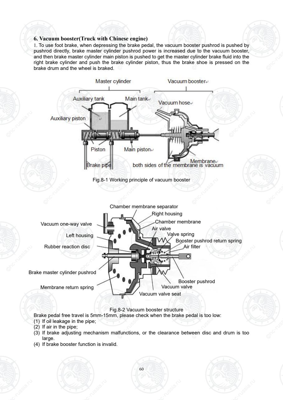
Страница 66
61
7. Hydraulic boosted braking assembly(Imported engine type)
Hydraulic boosted braking assembly refers to fig.4-5. It is composed by the joint of hydraulic
booster and brake master cylinder, boosted part is applied hydraulic oil, and brake master cylinder
applied brake fluid.
Boosted part uses power from multi-way valve to pressurize master cylinder part. Hydraulic
feedback system in the component feeds back to operator a pedal force that is directly
proportional to brake pressure, so it is easy to do braking control adjustment.
Brake master cylinder can be operated manually at any time through assisted part. Brake pressure
formed by manual operation depends on the applied pushrod force.
1 2 3
4
5
1. brake master cylinder assy 2. Nut M8 3. Washer 8 4. Shim 5. Hydraulic booster
Fig.4-5 Hydraulic boosted braking assembly
7.1 Hydraulic booster
Hydraulic booster and steering system share the same hydraulic oil, they can work separately, or joint
to use when necessary, but do not intervene mutually.
Оригинальная страница: таблицы и схемы
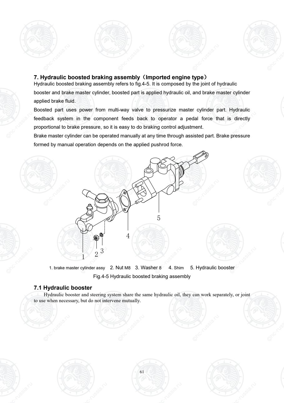
Страница 67
62
To brake master cylinder
Oil port connection:P: Connect the oil-out of steering gear pump
T: Connect oil return pipe of hydraulic oil tank
PS: Connect P port of hydraulic steering gear
Fig.4-6 Hydraulic booster shape and working principle
Fig. 4-7 Hydraulic booster structure
Оригинальная страница: таблицы и схемы
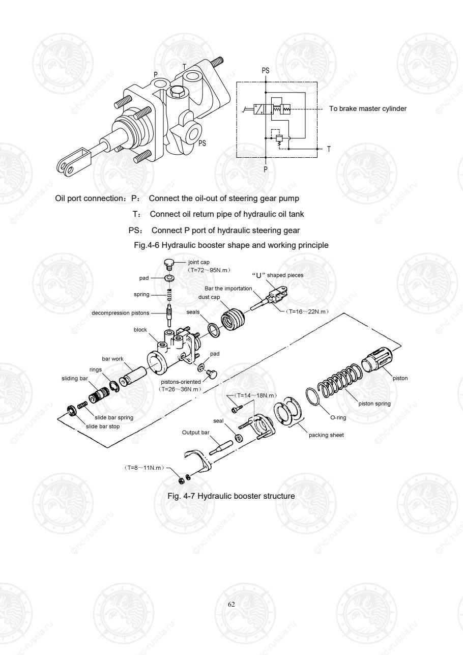
Страница 68
63
Hydraulic booster dismantle
– Dismantle rod connector and input rod.
– Remove the brake booster nuts from
pedal bracket.
– Dismantle the pipeline from brake master
cylinder to brake booster.
– Take down brake booster and brake
master cylinder.
– Separate brake booster and brake master
cylinder.
To install, reverse removal procedures.
Caution
After dismantling pipeline, avoid
dust and impurity getting into inner
cavity.
Hydraulic booster disassembly
– Remove dust cap and input rod.
– Remove guiding rod and output rod.
– Remove O-ring, piston spring and washer.
– Dismantle piston guiding.
– Remove piston and working beam.
– Remove snap ring and pull out slide bar,
spring and baffle plate from piston.
– Remove plug, reducing valve and spring,
do not disassemble reducing valve
assembly.
To reinstall spare parts, reverse the
disassembly procedure.
Inspect
– Check sealing gasket and replace if
damaged.
– Replace damaged O-ring.
– Check if there is scratch or wear on
cylinder body, piston, slide bar, working
beam, output rod, guiding rod, reducing
valve assembly and piston guiding sliding
surface, replace if necessary.
Attention to reinstall hydraulic booster:
– Use light oil(not gasoline) to clean parts.
Оригинальная страница: таблицы и схемы
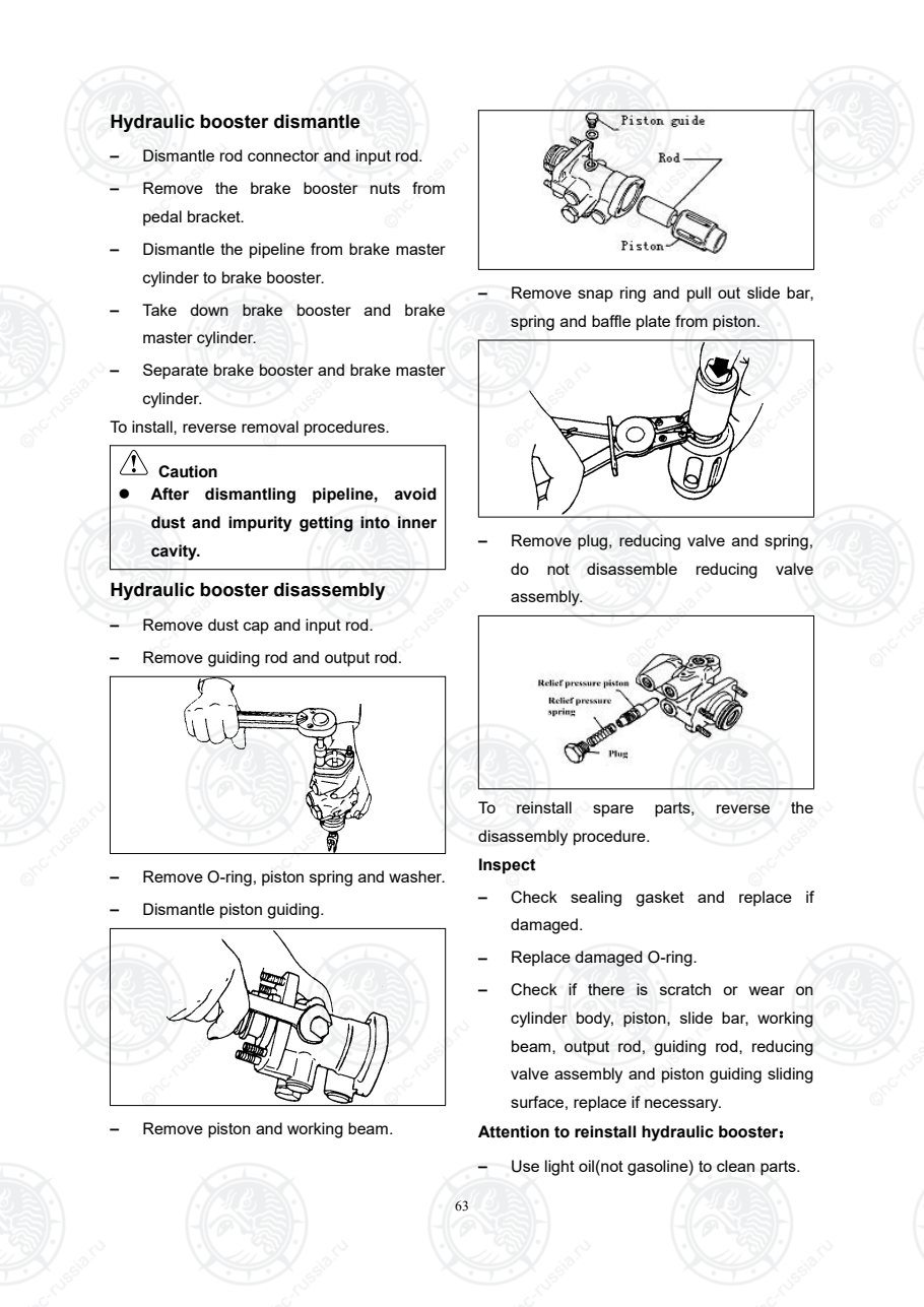
Страница 69
64
– Avoid impurity get into parts inner cavity.
– Apply hydraulic oil to the moving part
surface before assembling.
– Pay attention to the direction when
assembling reducing valve assembly and
slide bar.
– Do not install the slide bar reversely.
– Install the snap ring in place.
– Insert
piston and working beam into cylinder
body and make sure piston groove
direction. The below figure shows the
mounting position of brake master
cylinder and tightening position of piston
guide. Piston guide tightening torque is
26~36N·m.
– Install guide rod to downward the air vent.
– Install dust cover to downward the air
vent.
– After installing cylinder body, piston,
output rod or guide rod, adjust the
projected length of output rod with shim.
Projected length is 18±0.1mm.
Hydraulic booster fault diagnoses and corrections
condition Probable cause Corrective action
Brake does not work efficiently
Oil leakage Repair or add oil
Oil pump or priority valve
failure Repair or add oil
Impurity in the slide bar
valve Clean or replace
Impurity in the reducing
valve Clean or replace
Oil seal wear or leakage Replace
Hard brake Slide bar valve failure Replace
Brake locking
Oil pressure is not zero when
releasing the pedal)
Impurity in the slide valve Clean or replace
Output rod absorbs impurity Clean or replace
Оригинальная страница: таблицы и схемы
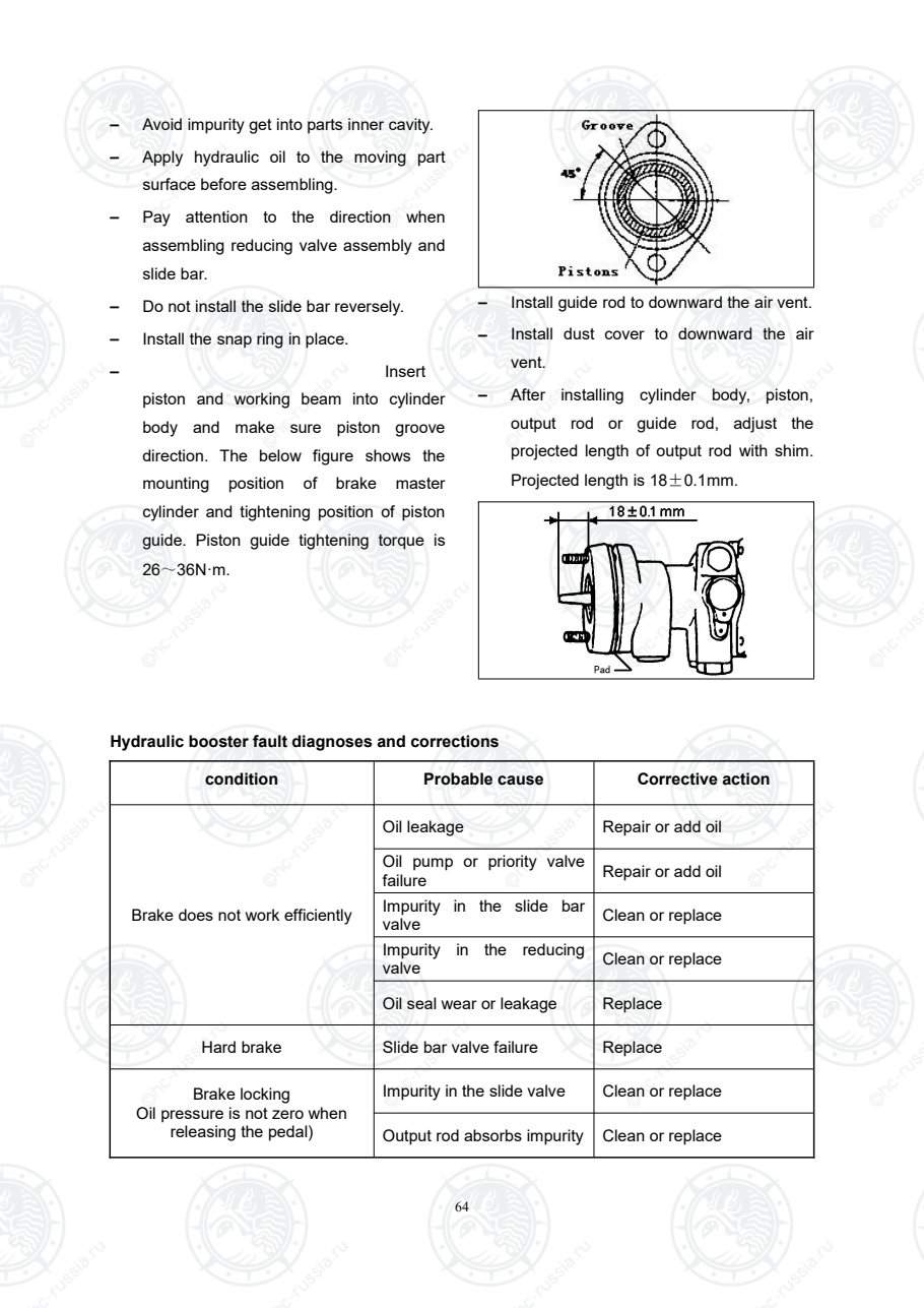
Страница 70
65
7.2 Brake master cylinder
Brake master cylinder structure refers to fig. 4-8. End part is fixed with internal circlip, and the
master cylinder piston operates with the help of controlling brake pedal through hydraulic booster
output rod.
Fig. 4-8 Brake master cylinder
7.2.1 Remove
1) Take apart brake master cylinder and brake booster.
2) Take apart snap ring, piston, stop washer, spring bracket and spring.
7.2.3 Inspection
Check the master cylinder’s parts in brake fluid for damage and deformation.
Num. Condition Method
1 There is excessive wear or damage on the surface of piston or cylinder Replace
2 The clearance between piston and cylinder is bigger than 0.15mm Replace
3 The leather bowl is weak and damaged Replace
4 Spring loosen or damage Replace
5 Reservoir oil tank deformation or damage Replace
Caution:
·Through away the primary cup and replace a new one.
·Keep the work plane clean.
·You can’t use other fluid or oil but brake fluid.
Оригинальная страница: таблицы и схемы
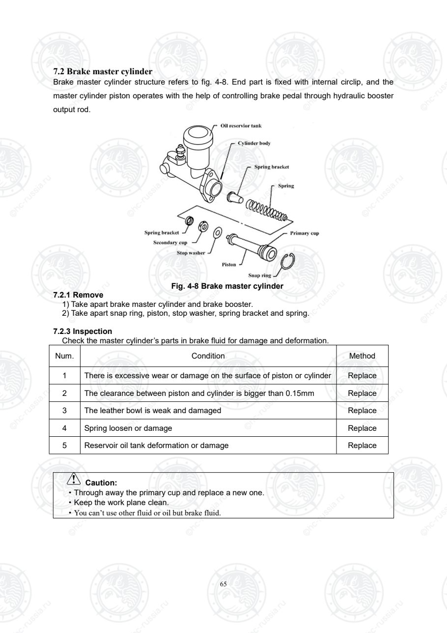
Страница 71
66
7.2.3 Assembly
To install, reverse the order of removal.
Caution:
1) Clean the parts in brake fluid.
2) Daub brake fluid on the frictional surface of piston and cylinder.
3) It is forbidden to cut and damage the surface of the piston.
4) The position of the piston cup and spring bracket must be correct (refer to fig.4-9)
Fig. 4-9 Cup、spring bracket position
Brake master cylinder disassembly
– Separate brake master cylinder and brake pedal.
– Take down snap ring, remove piston, insulation pad, spring seat and return spring.
Check
Clean all parts in the brake fluid and check their condition.
Serial No. Check condition Corrective action
1 Obvious scratch or wear on moving surface of
cylinder and piston Replace
2 Clearance between cylinder body and piston
should not exceed 0.15mm. Replace
3 Weak and damaged auxiliary leather collar
and pressure leather collar Replace
4 Weak and damaged spring Replace
Caution
Throw away the removed leather collar, and replace with new one.
Remove the parts in clean ground and place them in sequence neatly.
Do not use other cleaning agent to clean parts.
Оригинальная страница: таблицы и схемы
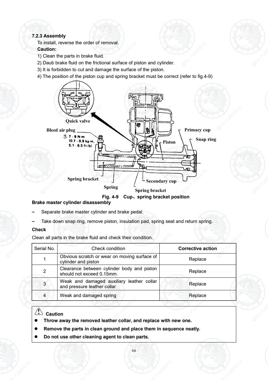
Страница 72
67
8. Fault diagnoses and corrections
Fault Probable cause Corrective action
Insufficient brake
force
Oil leakage in brake lines
Air in brake lines
Water or oil on linings
Uneven wear or contact of linings
Improper functioning of brake valve
Clogged oil lines
Correct and replenish
Bleed air
Clean or replace
Grind or replace
Correct or replace.
Clean
Unequal braking
(forklift truck veers
to one side)
Uneven tire pressure.
Improper brake adjustment
Water or oil on brake linings
Foreign pieces in brake drum
Damage on friction lining
Improper contact of friction linings
Worn friction lining
Worn, warped, rusted or damaged brake
drums
Improper operation of brake cylinder
Incorrect brake shoe sliding
Guard plate bolt looseness
Guard plate warp
Improperly adjusted wheel bearing
Clogged oil lines
Adjust
Adjust
Wipe or replace
Clean
Grind or replace
Grind or correct
Replace
Correct or replace
Correct or replace
Adjust
Tighten or replace
Replace
Adjust or replace
Clean
Brake dragging
No free play of brake pedal.
Incorrect brake shoe sliding
Incorrect brake cylinder operation
Damage piston cup
Weak or broken return springs
Back-flow hole of brake master cylinder
blockage
Clogged oil lines.
Incorrect wheel bearing adjustment
Adjust
Adjust
Adjust or replace
Replace
Replace
Clean
Clean
Adjust or replace
Brake noise
Lining surface harden or foreign pieces
on it.
Warped back plates or loosed blots.
Brake shoes warped or improper install.
Worn linings.
Loose wheel bearing.
Repair or replace
Repair or replace
Repair or replace
Replace
Repair
Оригинальная страница: таблицы и схемы
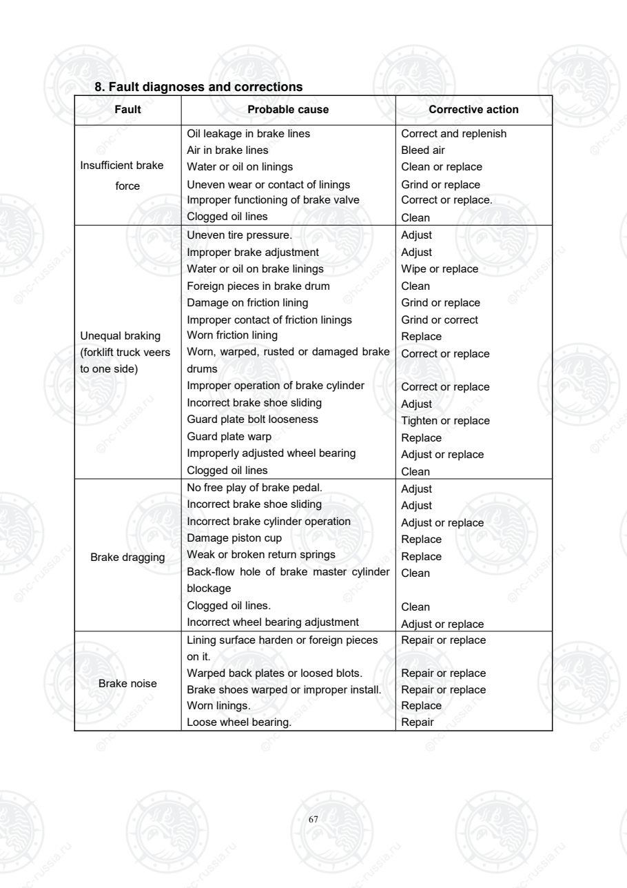
Страница 73
68
9. Brake schematic
Fig. 4-9 Drum brake(Vacuum boost)
Fig. 4-10 Drum brake(Hydraulic boost)
Оригинальная страница: таблицы и схемы
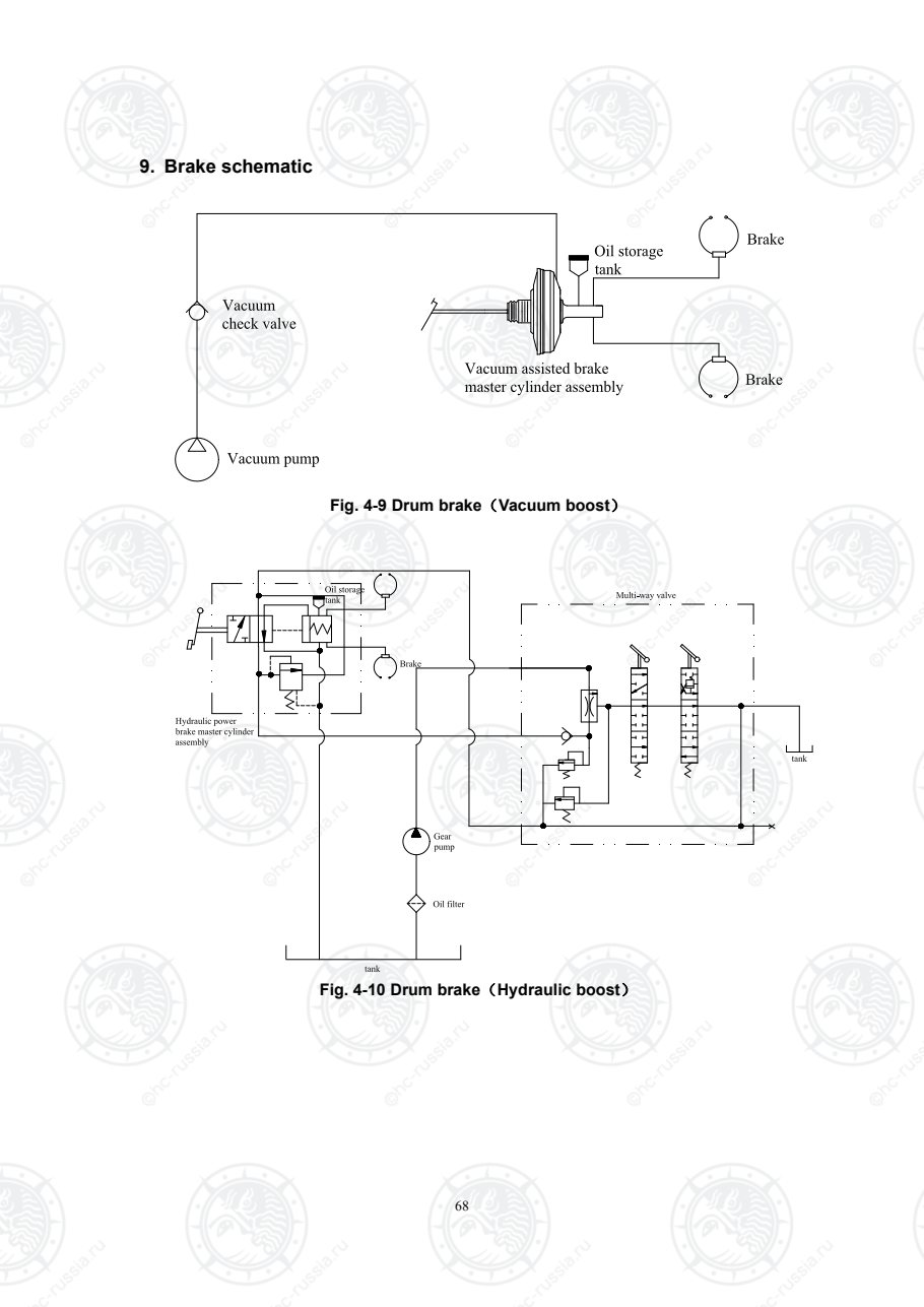
Страница 74
69
Ⅴ.Hydraulic system
1.Data
Main pump
Model CBQ-F550-AFHL
Type Gear
Driving Engine power output gear transmit
Displacement (ml/r) 50
Rotated Speed (r/min) 600~3000
Output pressure (Rated/Max) MPa 20/25
多路阀
公称压力 20MPa
额定流量 160L/min
主安全阀调定压力 19±0.25 MPa
转向安全阀调定压力 9±0.25 MPa
过载发调定压力 15±0.25 Mpa
单稳分流阀分流量 13 L/min ~16L/min
Оригинальная страница: таблицы и схемы
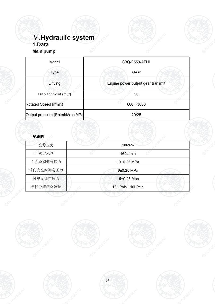
Страница 75
70
2.Trouble diagnoses and corrections
Main pump
Trouble Probable cause Corrective action
No oil from oil
pump
Low oil level in tank. Add oil to specified level.
Clogged suction pipe or
strainer.
Clean oil line and tank. If oil is dirty,
change.
Low discharge
pressure on oil
pump.
Worn bearing damaged
backup ring and O-ring.
Replace faulty parts.
Maladjusted relief valve.
Readjust to specified pressure using
pressure gauge.
Air in oil pump.
Retighten suction side pipe.
Add oil in oil tank.
Check pumps oil seal.
Do not operate pump until bubbles in tank
disappear.
Noisy oil pump
Cavitations due to crushed
suction hose or clogged
strainer.
Adjust or replace crushed hose and clean
strainer.
Air being sucked from loose
suction side joint.
Retighten each joint.
Cavitations due to too high
oil viscosity.
·replace with new oil having proper
viscosity for temperature at which pump
is to be operate.
·to operate when oil temperature is
normal.
Bubbles in hydraulic oil. Determine cause of bubbles and remedy.
Oil leaking
from oil pump
Faulty oil seal on pump,
faulty O-ring or worn sliding
surfaces on pump.
Replace faulty parts.
Оригинальная страница: таблицы и схемы
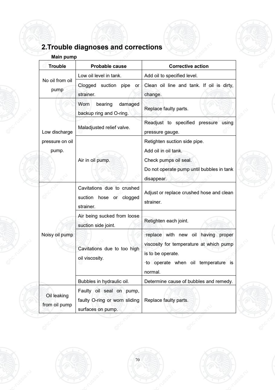
Страница 76
71
Control valve
Trouble Probable cause Corrective action
Pressure of relief
valve is not
steady or too low.
Loose of pressure-adjust screw. Readjusted and re-tighten.
Distorted or damaged pressure-adjust
spring. Replace.
Worn or blocked relief valve core. Replace or clean.
Pump abated. Examine and repair pump.
Fork tilt forward
when control
lever is used
while engine is
off.
Worn or damaged tilt lock valve. Replace valve core and tilt lock
valve as an assembly.
Broken tilting lock spring. Replace spring.
Damaged tilt valve plunger O-ring. Replace O-ring.
Mast is unstable
when tilting
forward.
Malfunctioning tilt relief valve. Replace tilt relief valve
assembly.
Lowering
distance of mast
is big when spool
valve is in the
centre.
Valve body and spool valve is worn
and clearance between them is too
great.
Replace spool valve with
specified clearance.
Spool valve is not in centre. Keep being in the centre.
Cylinder seal abated. Examine and repair cylinder.
Taper valve is worn or blocked by dirt. Replace or clean taper valve.
Spool valve is not
return neutral
position.
Damaged or distorted
reposition-spring. Replace spring.
Dirt exist between valve body and
spool valve. Clean.
Blocked control device. Adjusted.
Not coaxial parts at reposition Reinstall.,be coaxial
Leakage
Damaged O-ring. Replace.
Faulty seal of joint. Check and retighten.
Loose seal plate. Clean seal plate and retighten
blots.
Loosed lock-nut of relief valve and
connect-nut between plate and plate. Tighten.
Steering is heavy.
Valve disk of priority is blocked. Adjust.
Signal port is jammed. Clean
Оригинальная страница: таблицы и схемы
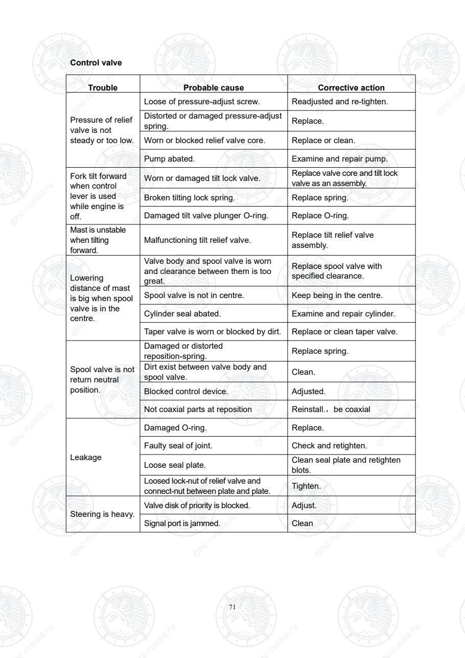
Страница 77
72
3.Main pump
The main pump is a gear type consisting of a pump body; pump cover, a pair of gear,
bearing and seal ring. This pump uses pressure-balance type bearing and a special
lubrication method so as to get the minimum clearance of the gear flank.
Since the pump body and cover are made of aluminum alloy, they are light and rigid.
The drive gear and driven gear are integrated with their respective shafts, which are held
against the pump body with bearing. The bearing made of special material, serves both as
bearing for each shaft and as side plates for the gear flank.
At the drive shaft side, an oil seal is press-fitted into the pump body to provide oil
tightness performance. Oil tightness between pump body and pump cover is secured with
a packing of a special shape.
Fig. 6-1 Anti-clockwise rotation gear pump
1. End cover 2. Pump body 3. Bearing 4. Bearing
5.Drivegear 6.Driven gear 7. Forward end cover 8. Seal ring
9. Seal ring 10.Seal ring 11. Seal ring 12.Bolt
13. Lock washer 14. Seal 15.Lockring
Оригинальная страница: таблицы и схемы
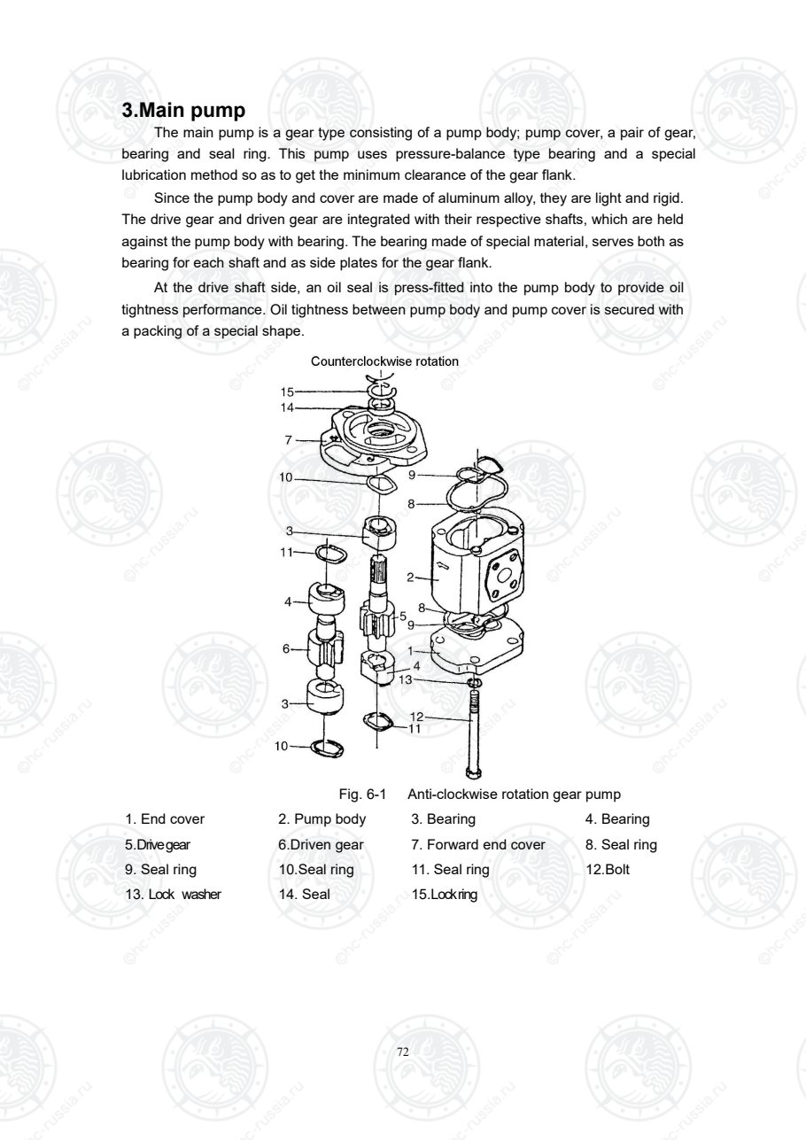
Страница 78
73
4. Multi-pathway valve
4.1 Summary
Two pieces type multi-pathway valve consists of inlet, outlet and slide valve. Dividing
valve and main safety valve are installed at the inlet.
The main safety valve can adjust oil pressure of the control oil pipe. Its pressure has
been adjusted when it is on sale, please don’t adjust it without permission.
Steering safety valve is used to adjust the oil pressure of power steering oil pipe.
Slide valve controls the raise, tilt oil cylinder. It makes the oil flux changed by operating
raise and tilt valve stems in order to control the oil cylinders.
Tilt slide valve is equipped with front-tilt self-lock valve. oil from hydro cylinder returns
to oil box from output, and every piece of valve is sealed by maneuver “O”ring. At the
same time, there are installed a single direction valve. Refer to fig. 7-2.
Fig. 6-2 Multi-pathway valve
4.2 Adjusting the pressure of the main safety valve
The main relieve valve has been adjusted before leaving the factory, , it is not allowed to
adjust at will in general condition. Adjusting way is as follows:
(1) Park the truck on solid and smooth road, place in neutral, pull up the hand brake
handle, tilt the mast backwards to the end, and drop the fork to the ground. The
engine stops.
(2) Open front soleplate, release the pressure mouth bolt of oil inlet pipeline in the
multi-way valve, and put in clean place. If hydraulic oil outflows, please protect the
environment.
Оригинальная страница: таблицы и схемы
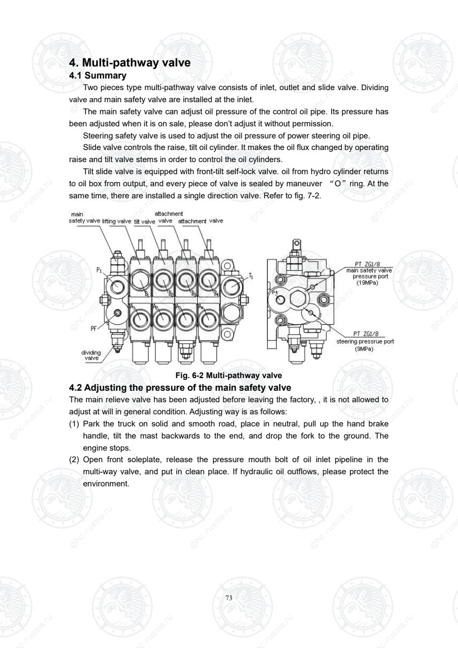
Страница 79
74
+
-
(3) Connect the pressure gauge. Notice: a. Specification of gauge should be larger than
20Mpa. b. taper thread at pressure mouth matches: Rc1/8R1/8; c. tightening torque is
20-22N•m.
(4) Start the engine, place the mast in vertical, and the fork is 300mm from the ground.
(5) Read out the indication in the pressure gauge, and judge is the main safety valve of
multi-way valve is in normal scope.
4.0t~X5t:19.5MPa±0.25 MPa
(6) If the pressure is not in the normal scope, please release the main safety valve lock
nut, and adjust adjusting bolt.
If the indication is smaller than the normal scope, inner hexagon spanner the adjusting
bolt in clockwise (+) to increase main safety valve pressure.
If the indication is larger than normal scope, inner hexagon spanner the adjusting bolt
in counterclockwise (-) to decrease main safety valve pressure.
(7) Stable the pressure in normal scope for 30’s.
(8) Release pressure gauge, install the bolt, and the tightening torque is 20-22N•m. Drop
the mast to the ground and tilt backward to end.
(9) Retighten the tightening nut, and fix it on the front soleplate.
Оригинальная страница: таблицы и схемы
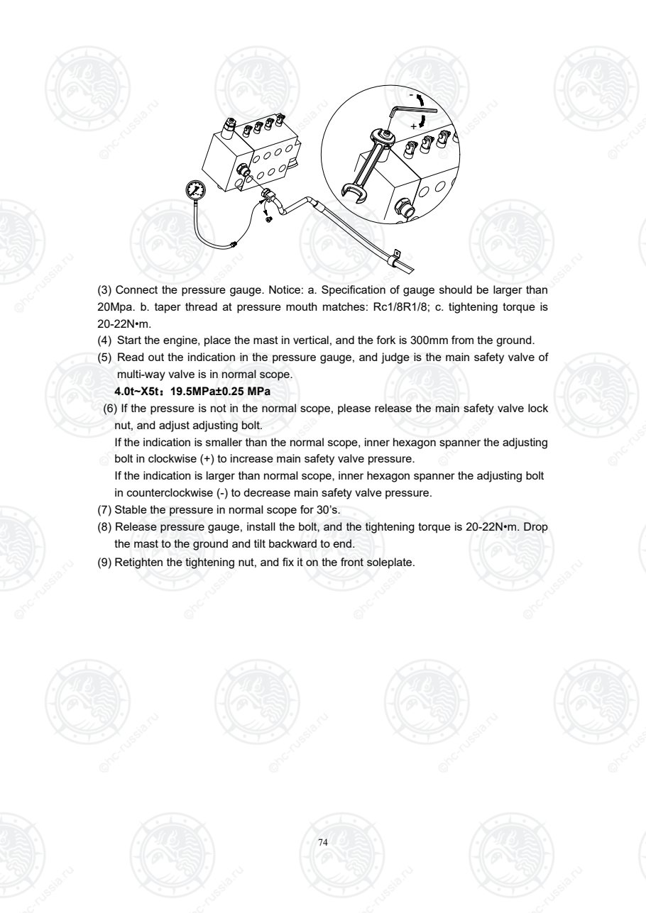
Страница 80
75
5. Hydraulic system circuit
Imports of engine forklift truck
The high pressure oil from main pump goes to control valve and divide it to two parts by
dividing valve inside control valve: one of them goes to control valve and then goes to
lifting cylinder or tilting cylinder, another part goes to steering gear to control steering
cylinder. When lifting and tilting spools are in neutral, high pressure oil returns oil tank
directly from passway. When pulling lifting spool, high pressure oil goes by throttle valve
and then push piston rod under lifting cylinder piston. When pushing lifting spool, it is that
bottom of lifting cylinder piston connects with low pressure line and then piston rod drops
by deadweight and weight of cargo. In this time, oil from lifting cylinder goes by
unidirectional speed limiting valve so as to control the falling speed. When operating tilting
spool, high pressure oil goes to front house of tilting cylinder and another connects with
low pressure line so as to make mast tilt forward or backward.
When press the brake pedal, the rod of the brake booster be pushed, the
slide valve open, the high-pressure oil goes into piston and push the piston to
push the brake master cylinder, and make the function of brake booster. The
structure of brake booster, please see the chapter about brake system.
Fig. 6-3 Hydraulic system principle diagram
Оригинальная страница: таблицы и схемы
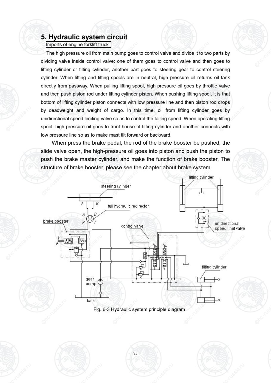
Страница 81
76
Domestic engine forklift truck
The high pressure oil from main pump goes to control valve and divide it to two parts
by dividing valve inside control valve: one of them goes to control valve and then goes to
lifting cylinder or tilting cylinder, another part goes to steering gear to control steering
cylinder. When lifting and tilting spools are in neutral, high pressure oil returns oil tank
directly from pass way. When pulling lifting spool, high pressure oil goes by throttle valve
and then push piston rod under lifting cylinder piston. When pushing lifting spool, it is that
bottom of lifting cylinder piston connects with low pressure line and then piston rod drops
by deadweight and weight of cargo. In this time, oil from lifting cylinder goes by
unidirectional speed limiting valve so as to control the falling speed. When operating tilting
spool, high pressure oil goes to front house of tilting cylinder and another connects with
low pressure line so as to make mast tilt forward or backward.
Fig. 6-4 Hydraulic system principle diagram
Оригинальная страница: таблицы и схемы
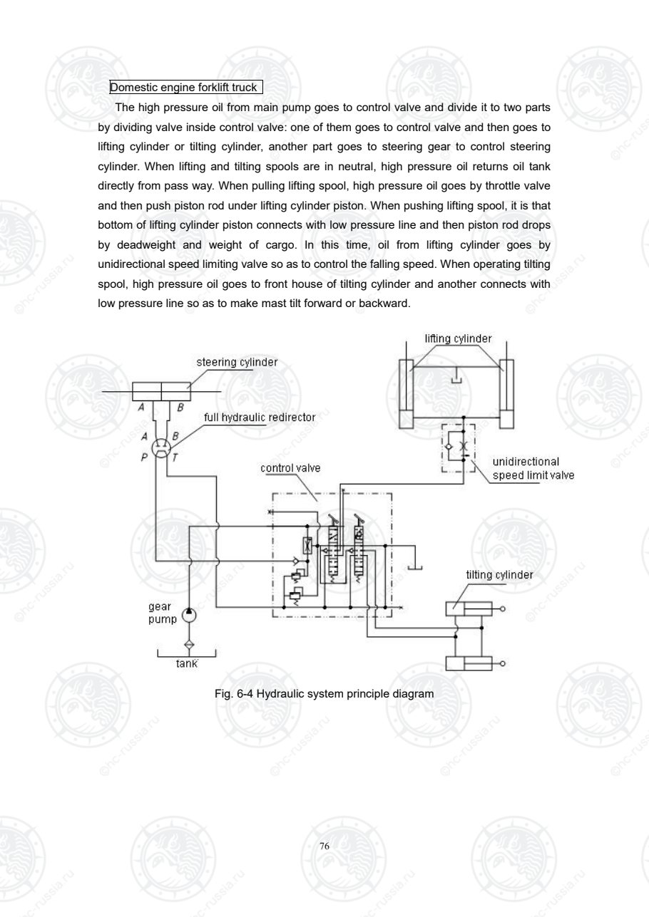
Страница 82
77
Dipstick Gear pump
Air breathing filter
Steering cylinder
Full hydraulic
steering gear One way speed
limiting valve
Lifting cylinder
Tilt cylinder
Gear pump
Fig. 6-5 Stone forklift Hydraulic system principle diagram
Оригинальная страница: таблицы и схемы
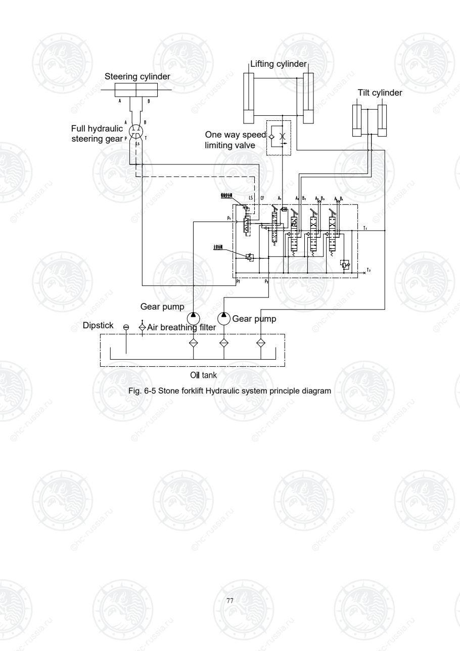
Страница 83
78
Ⅵ. Lifting system
1. Summary
The lifting system is composed of inner and outer mast, fork arm carrier, fork arm,
load backrest, chain, roller, lifting jack, and tilt cylinder, etc. Oil line system, hydraulic
pressure system and it compose fork lift truck work equipment. This equipment is
performing framework of load and unload. Commonly common mast has simple mast,
double mast and Triple mast class mast framework type. Fork lift truck what is made in our
company backing boardch Double high visibility mast, Double full free lift mast (including
container mast), Triple full free lift mast, mast framework adopted is CL model
juxtaposition roller type.
Double high visibility mast
Double mast is composed of outer mast which can’t lift and inner mast which can lift.
Lifting jack bottom is fixed on outer mast below cross beam, oriented with pin. Piston rod
extremity is joined with upper cross beam of inner mast; cylinder body is fixed on outer
mast fixation board with U-bolt. Commonly free lift range is 100 mm ~145mm, which is
difference with different tonnage. Two lifting jacks (fig.7-5 is right)are laid out back of
outer mast to realize high visibility; two lifting jacks are laid outside of outer mast.
Fork arm is hung on fork arm carrier by hook. Roller, combined roller (side roller is
installed middle of roller outside) and side roller (It is adopted combined roller in 1-1.8
tonnage fork lift truck) is installed on fork arm carrier. Combined roller is installed on below
of inner mast.
Pressure oil from hydraulic control valve is entered into lifting jack by unidirectional
speed limiting valve, forced piston and piston rod rising, thereby forced inner mast rising.
At the same time one end of lifting chain on inner mast is fixed on outer mast, the other is
joined with fork arm carrier. Fork arm carrier and fork arm is rising with inner mast rising to
realize aim of lifting goods.
Basic truck mast supplied by our company is 3M, and special order is as follows:
Duplex wide view mast:2.5M to 6M
Duplex full free lift mast:2.5M to 3.7M
Triplex full free lift mast:4M to 7M
Оригинальная страница: таблицы и схемы
Страница 84
79
Fig. 7-1 Double stage wide view mast
1.Outer mast 2. Inner mast 3. Load-backrest 4. Fork arm carrier 5. Fork arms
6.Chain 7.Left lifting cylinder 8.Right lifting cylinder 9. Tilting cylinder 10.Roller
2. Assemble debugging data
Debugging data Double mast and triple mast
Mast type
Standard type and
lifting height of 2~4
meter
Lifting height
>4~5 meter
Lifting height
> 5~6 meter
Mast
tilt
angle
For-ward 6° 6° 3°
Back-ward 12° 6° 6°
Fork arm carrier roller
Adopt combination roller and side roller if rated capacity is less than
3 .5t.
Inspection and adjustment
Place Assembly clearance (mm) Repair clearance(mm)
Mast to lift roller 0.1~0.8 0.2~1
Shims 0.5,1.0,2.0
Mast to back up metal 0.1~0.8 0.2~1
Shims 0.5,1.0,2.0
Inner mast to carriage side
roller
0.1~0.6 0.2~1
Shims 0.5,1.0,1.5
Lift chain deflection 25~30
Оригинальная страница: таблицы и схемы
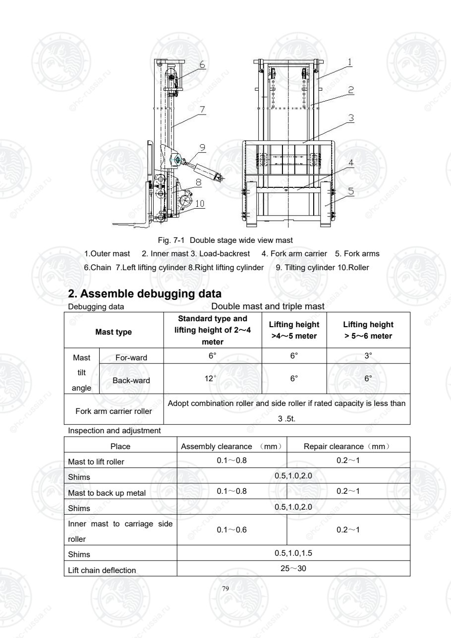
Страница 85
80
Tightening torque
Place Model or Lifting capacity N·m
Lift chain lock nut
1t-1.8t 193-257(M16)
2t~3.5t 245-314(M20)
Mast support cap blot
1t-1.8t 124-165(M14)
2t~3.5t 176-216(M18)
Tilt cylinder lock nut
1t-1.8t
89-118(M14)
2t~3.5t
Lift cylinder bolt(top)
1t-1.8t
76-107(M12)
2t~3.5t
Lift cylinder bolt(bottom)
1t-1.8t
22-30(M8)
2~3.5t
Lift cylinder fixing bolt
(cylinder clamp bolt)
1t-1.8t
76-107(M12)
2t~3.5t
Place Tightening torque (N·m)
Lifting chain locknut 441~539(M24×2)
Bearing cap of mast and drive axle 245~314(M20×1.5)
Tilting cylinder locknut 49~64(M12)
Lifting cylinder bolt 127~157(M16)
Lifting cylinder fixing bolt(U-bolt) 10~12(M8)
Оригинальная страница: таблицы и схемы
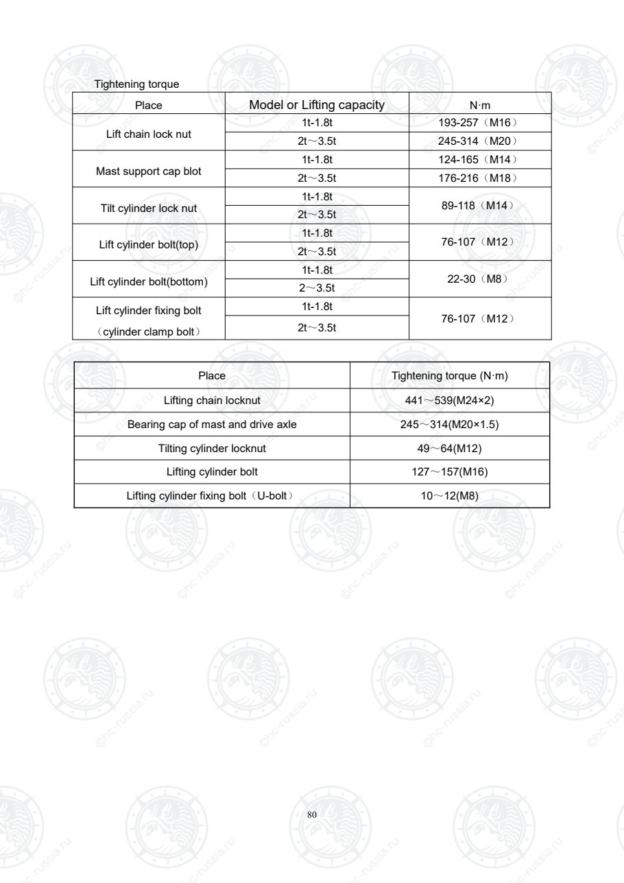
Страница 86
81
3.Trouble diagnoses and corrections
Condition Probable cause Corrective action
Fork arm
carrier
or mast tilt by
itself.
1.Tilt cylinder and ring
abraded excessively Replace piston ring tilt cylinder.
2. The hydraulic control
valve spring is inoperative. Replace it.
The fork arms
carrier moves
up
and down
sluggishly.
1. Caused by piston
jamming or bent piston rod. Replace the faulty parts.
2. Too much dirt is
accumulated in the cylinder. Strip it down and clean.
Forks are lifted
or lowered
non-smoothly.
1. Carriage bracket
assembly out of adjustment.
Adjust clearance with thrust metal and
carriage side roller.
2. Insufficient clearance
between inner and outer
masts or rollers and mast.
Adjust clearance with rollers.
3. Biting foreign backing
boarderials between
moving part.
Remove foreign backing boarderials.
4. Insufficient lubrication. Apply grease on contact surfaces of
sliding parts.(butter)
5. Bent carriage bracket
assembly. Repair or replace.
Forks are lifted
unevenly
1. Lift chains out of
adjustable. Adjust lift chains.
Lift roller does
not rotate
1. Grease stiffened or dirt
accumulated on lift roller
and mast sliding surfaces.
Clean and lubricate lift rollers.
2. Improperly adjusted lift
roller. Adjust.
Excessive mast
noise
1. Insufficient lubrication. Lubricate.
2. Improperly adjusted lift
roller, side roller and
back-up metal.
Adjust.
3. Rubber pad on lower of
outer mast is useless for
container fork lift truck.
By adjusting shims and rubber pad,
piston rod is in touch with bottom of
cylinder body after inner mast is in touch
with rubber pad.
Оригинальная страница: таблицы и схемы
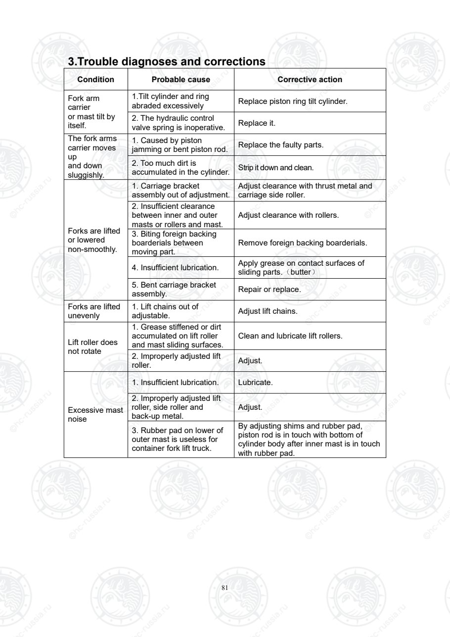
Страница 87
82
Condition Probable cause Corrective action
Insufficient lift
power or no lift
movement.
1. Excessive wear occurs
between the oil pump body
and gears, causing too
much clearance.
Replace the worn parts or the oil pump
2. The lifting jack piston
Yx-ring has worn, resulting in
excessive inner leaks.
Replace Yx-ring.
3. Springs of the multiple
control valves and its relief
valve are inoperative oil
leaks.
Replace.
4. Excessive wear occurs
of the hydraulic control
valve, resulting in
excessive oil leaks.
Replace.
5. Oil leaks occur between
the hydraulic control valve
sections.
Dismantle for regrinding the joint
surfaces and reassemble the valve.
6. Leakage occurs in the
hydraulic pipe.
Tighten the joint nuts and inspect the
seal for damage.
7. The hydraulic oil
temperature is too high. Oil
viscosity is too low and the
rate is insufficient.
Change the wrong hydraulic oil or stop
operation for reducing the oil
temperature. Find out the reasons for
high oil temperature and eliminate the
trouble.
8. The load carried is
beyond the designed
capacity.
Observe the lifting capacity limit.
Оригинальная страница: таблицы и схемы
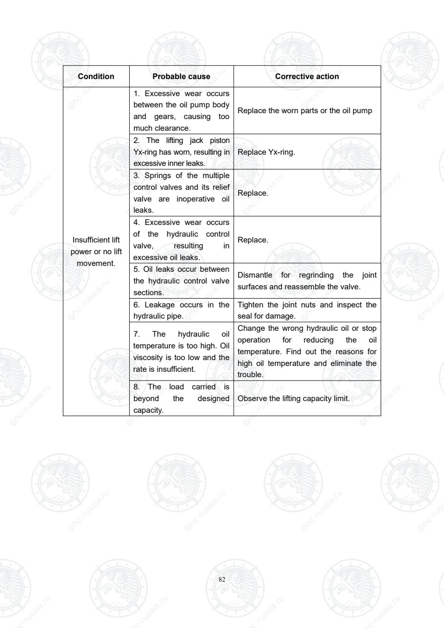
Страница 88
83
Lifting assembly
T —Tightening torque refer to foregoing table
Оригинальная страница: таблицы и схемы
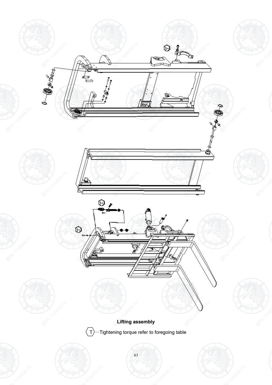
Страница 89
84
4. Removal and adjustment
! WARNING
Be careful when removing and
installing the forks, carriage and mast as
they are heavy.
4.1 Remove forks and mast assembly
1) Unlock fork lock pins by pulling them
and move forks to cutout portion in the
middle of carriage bracket assembly.
2) Pull lower portion of fork to remove
its lower jaw and lift it out.
! WARNING
a. Keep hands and feet away from forks.
When removing and installing forks
carefully, keep feet and hands clear.
b. Do not remove forks from the end of
the fork bar. Severe injury can
result if the fork is dropped.
1) Attach wire ropes to carriage bracket
assembly and lift carriage bracket
assembly up with a lifting device.
2) Remove chain attaching nuts, and
detach chains from carriage bracket
assembly.
3) Remove carriage bracket assembly
from inner mast.
4) Detach high pressure hose, lift hose
and low pressure hose.
5) Support mast assembly with wire
ropes.
6) Pull out tilt cylinder pivot pin.
Оригинальная страница: таблицы и схемы
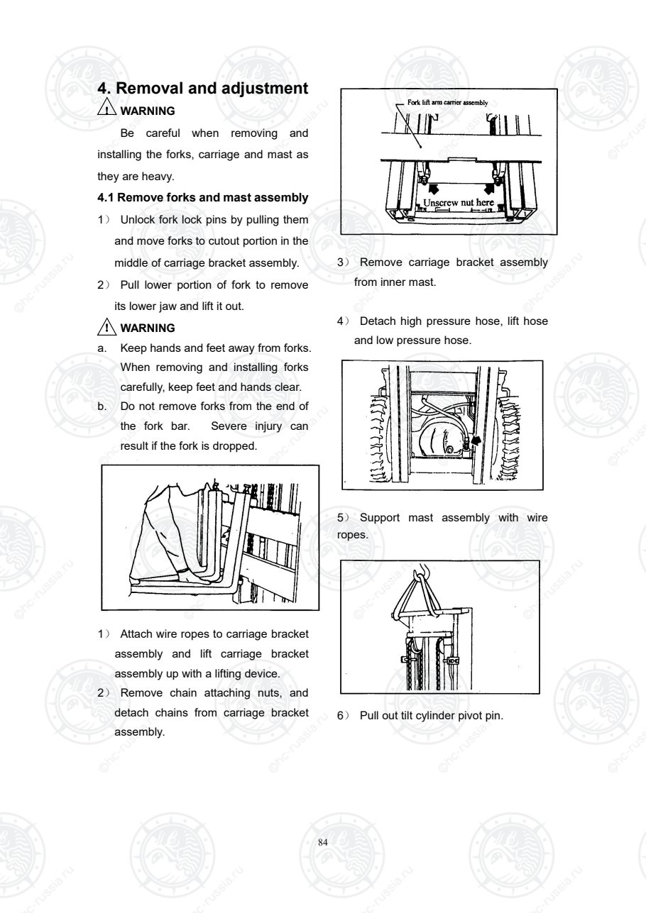
Страница 90
85
7) Remove mast support caps.
8) Remove mast assembly.
9) To install mast assembly, reverse
order of removal.
4.2 Disassembly
! WARNING
Be careful when disassembling the masts
as they are heavy.
Remove lifting jack
1) Place mast flat on ground. Remove
lifting jack attaching bolts-bolts and
tighten screw.
2) Slide inner mast, then remove lifting
cylinders.
Remove roller
1)Slide inner mast out until rollers are
exposed and remove little rollers with
bearing puller. Make two pieces of
round board about 10mm thick and
their diameter are Ф53 and Ф58,
covered on the seat of roller. Then
remove the compound roller and main
roller with bearing puller.
2)Unclench rollers carefully if no bearing
puller or rollers would be smashed.
Remove inner mast
Attach wire rope to middle of inner
mast and slide it out with a lifting device.
INSPECTION
1) Check lift rollers, roller shafts, and
associated parts for wear or damage.
2) Replace damaged parts as required.
4.3 Assembly and adjustment
Оригинальная страница: таблицы и схемы
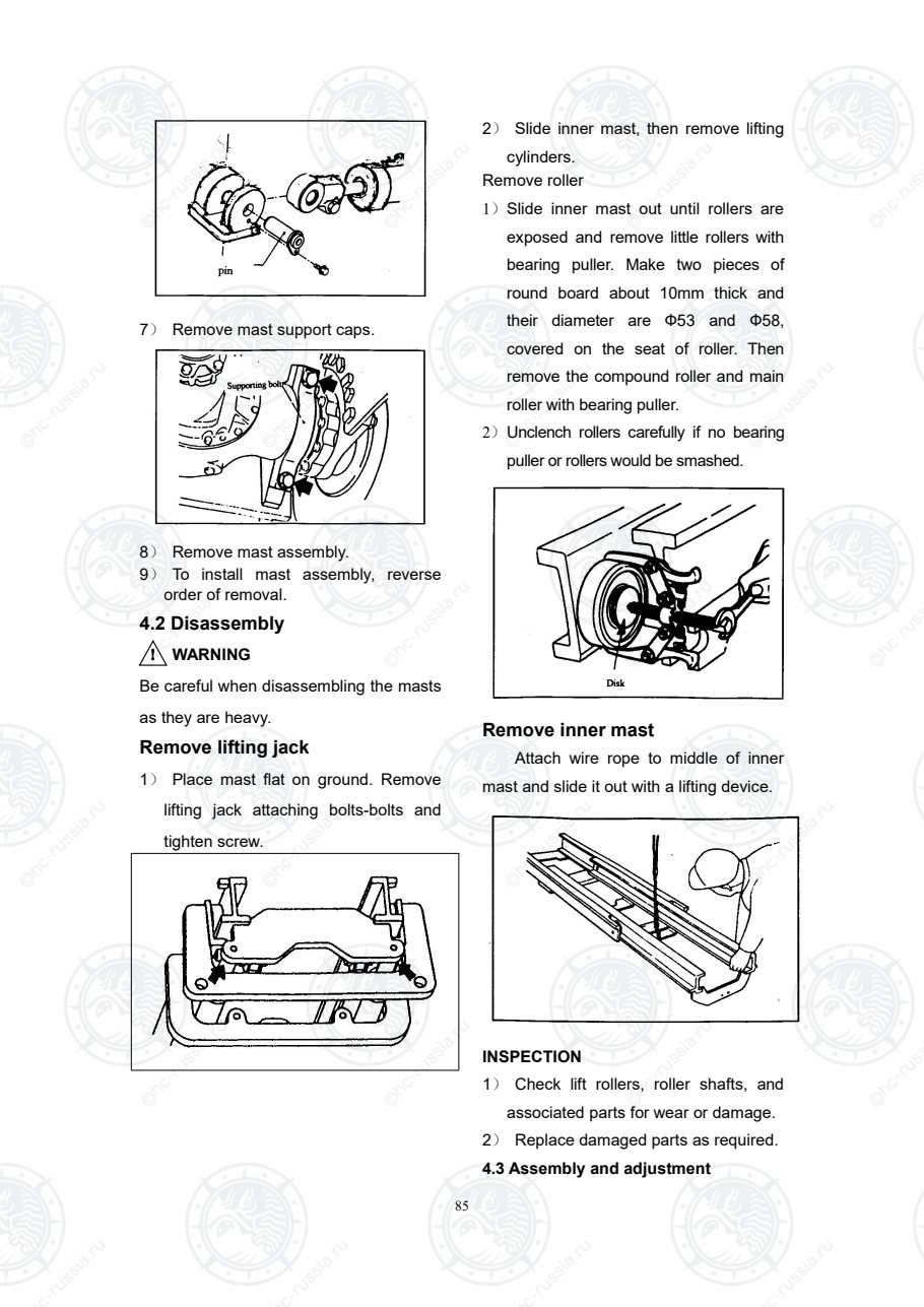
Страница 91
86
! WARNING
Be careful when assembling the masts
as they are heavy.
Lift roller
Slide inner mast into outer mast and
securely attach lift rollers.
Lift roller-to-mast clearance
adjustment
1) Set roller pitch of inner and outer
masts to “L” dimension. Then proceed
with the following adjustment.
Dimension “L” unit:mm
Model or
tonnage
Max.lift
height (mm)
Ⅲ grade
3 t
Ⅱgrade
2t~2.5t
2500~3300 368 328
3600 388 348
4000 418 378
4500 443 403
2) Adjustable range “A” with shims:
a. Dimension:0.1mm~0.6mm.(≤2 t)
b. Dimension:0mm ~ 0.5mm (2.5t ~ 3
t).One or two may not using rubber pad;
Dimension:0.1mm~ 0.6mm if no rubber
pad.
Orientation pin ensure that side roller is
vertical to inner mast track.
3) It is suitable that clearance of roller
and outer mast is about 0.8mm ~
1mm.Clearance can’t adjustable.
Replace it if roller wears too much.
4) Apply lubrication (butter) to interface
of inner mast and outer mast, interface
Оригинальная страница: таблицы и схемы
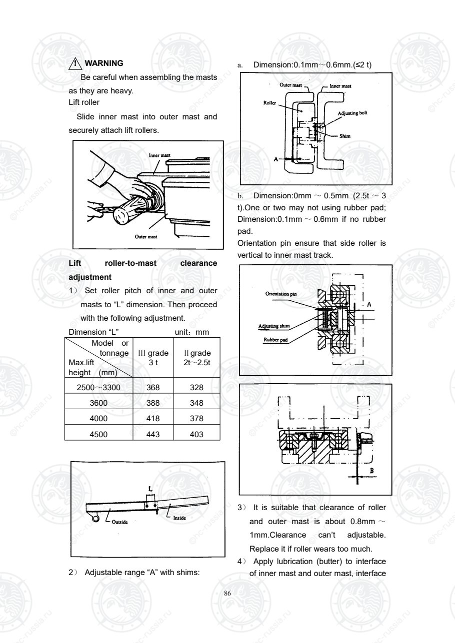
Страница 92
87
of roller and mast. To prevent sand
from entering, it is decided whether to
apply lubrication or not in the area
where sand blown by wind heavily.
Clearance of back up metal and mast
steel
Adjust clearance “B” to 0.1mm ~
0.8mm with shims, which may not use.
Thickness of shim is 0.5mm or 1mm.
Apply a coat of grease to back-up
metals. Install mast and lifting jack on
forklift truck. Connect circle tube and
high-pressure tube.
4.4 Left and right cylinder height
adjustment.
1)Install left and right lifting jack on mast,
pin must be installed into orientation
hole of outer mast lower cross beam.
2)Install upper of piston rod on inner mast.
Inner mast lay evenly in the direction of
left, right, upper and lower. If it is not
even, please adjust by putting washer
between hole of cylinder support and
upper end of piston rod.
3) Installs U-bolt onto cylinder,
hand-tighten nuts and lock it with two
tighten nuts. Screws down tighten bolt
and nuts to avoiding loosing.
4.5 Lifting chain adjustment
Installs fork arm carrier on inner mast,
and install lifting chain, then install two nuts
on end of every side. With mast set straight
up, lower carriage completely. Temporarily
adjust clearance of carriage to 74mm
-76mm above ground. If necessary, adjust
with chain adjusting nut.
To adjust tension of lift chain, lower
lifting jack until fork is on the ground ,and
adjust chain adjusting nut (three every
side) so that dimension C will be as listed
below when the middle portion of chain is
pressed by a finger.
Dimension C: 25 mm ~30 mm
Оригинальная страница: таблицы и схемы
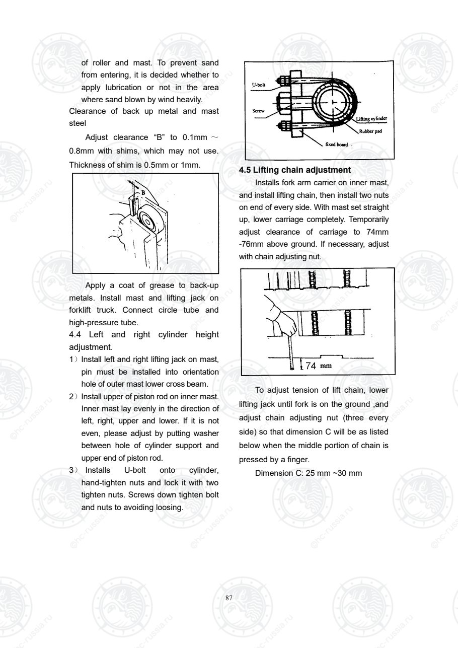
Страница 93
88
4.6 Clearance of fork arm carrier
assembly and rollers adjustment
1) Measure inside width “A” between
inner masts. Make measurements at
the top, bottom and center (cross
beam) sections.
2) Measure right and left pitches,B,B’,B”
of carriage side roller, carriage roller
and thrust metal.
3) Calculate A-B,A-Bˊand A- B".Each
result shows clearances between
each roller and inner mast. Adjust
shims of each roller evenly on the left
and right and make clearances,
between smallest part of inner mast
and carriage side roller.
A-B = 0.2mm~1 mm
A-B′= 0.1mm~0.8 mm
A- B" = 0.1mm~0.8 mm
Shims
0.5 mm 1 mm
a. Number of shims must be the same on
the right and left sides, when using
shims.
b. After clearance adjustment, push
carriage assembly to see if it operates
properly.
5. Disassembly and
installation of lifting jack
! WARNING
Keep body away from equipment
1) Turn out engine, then make lifting jack
falling into lowest condition that lower
of piton rod is touched bottom of
cylinder body so as to oil flowing back
tank completely.
2) Unscrew piston rod and bolt.
3) Disconnect circle oil pipe, remove
high pressure tubes.
Оригинальная страница: таблицы и схемы
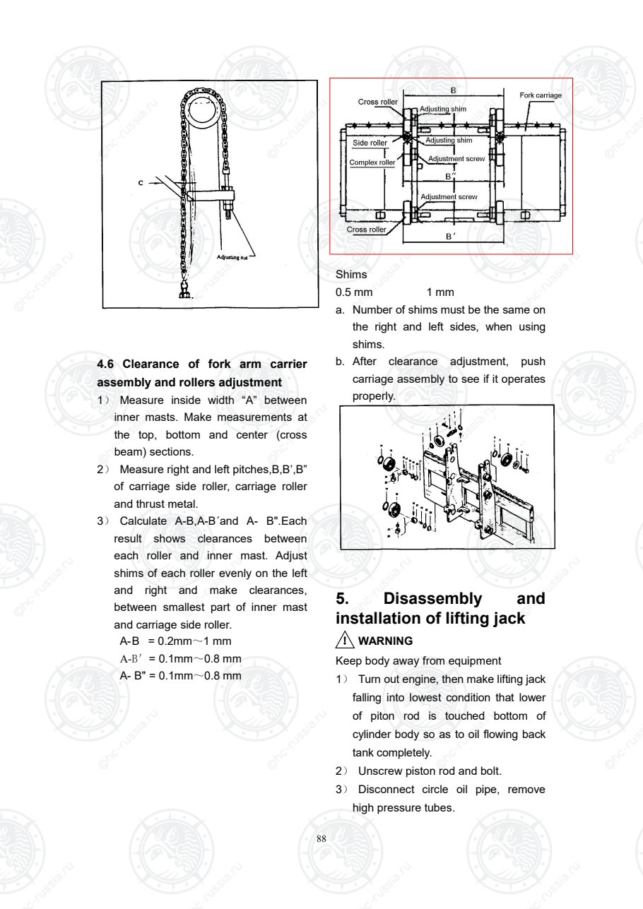
Страница 94
89
4) Remove U-bolt of outer mast fixation
board and tighten skew of other side.
5) Remove chain of outer mast.
6)Attach wire rope to inner mast and
remove left and right lifting jack with a
lifting device.
5.1 Disassembly
Rated capacity is less than 2.5 t
Remove cylinder head and guiding
bush
Rated capacity is more than 3 t
Removes tighten skew and nylon
stopper, then remove cylinder head.
1) Remove dust gasket ring.
2) Remove Y-ring with screwdriver.
CAUTION: Please not use dust gasket
ring removed, O-ring, Y-ring again,
must replace.
3) Draw out piston rod , remove Y-ring
on end of piston.
5.2 Install and replace faulty parts.
1) Cleanup parts with clean oil before
installation.
2) Then cleanup guiding bush and
piston with hydraulic pressure oil the
same as oil box trademark.
3) Dust or dunghill doesn’t drop into
lifting jack.
4) The order of installation is reverse
the order of disassembly.
5) Install Y-ring on piston.
6) Install piston rod assembly into clean
cylinder body.
CAUTION: The end of cylinder body
mast slick and clean, installation must
set center, avoid scratching Y-ring.
7) Install replacing dust gasket ring and
Y-ring in guiding bush and cylinder
head.
NOTICE:Apply hydraulic pressure grease
Оригинальная страница: таблицы и схемы
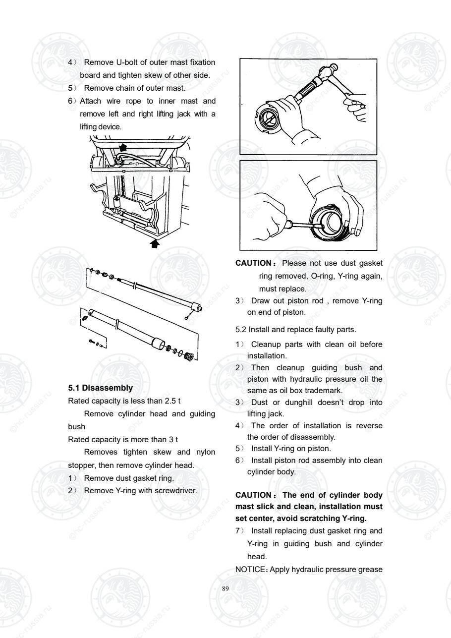
Страница 95
90
which trademark is the same as tank on
guide sleeve installed gasket ring
8) Rip cylinder head into piston rod,
screw down cylinder body.
6.Disassembly and
installation of tilting
cylinder
! WARNING
Notices proceedings when removing
cylinders.
·Attach wire rope to outer mast, avoiding
mast fall down after removing tilting
cylinder.
·Keep body away from equipment, no
standing under the fork arm carrier.
1) Lay down fork arm carrier completely.
2) Remove bolt on the left and right
bracket of outer mast, moreover pull axis
out.
3) Remove oil pipe to the inlet of tilting
cylinder.
4) Remove bolt on the bracket of
Chassis, and pull pin out, then move
tilting cylinder.
5) The order of installation is reverse
the order of disassembly.
6.1 Disassembly of parts
1) Squeeze tilting cylinder with pliers,
then pull piston rod come-and-go as
opening of inlet and outlet on the tilting
cylinder, so remaining oil is discharged
tilting cylinder.
2) Screw earring bolts 2 loosely, and
screw earring 1 out.
3) Remove cylinder head guiding bush
3;
4) Draw out piston rod assembly 4 (see
as follows).
5) Remove all dust gasket rings, O-ring
and Y-ring.
6)Remove dust gasket ring in the cylinder
head. Means is the same as discharging
of dust gasket ring in the cylinder head of
lifting jack (see disassembly and
installation of lifting jack).
7)Remove O-ring outside in the guiding
bush.
Оригинальная страница: таблицы и схемы
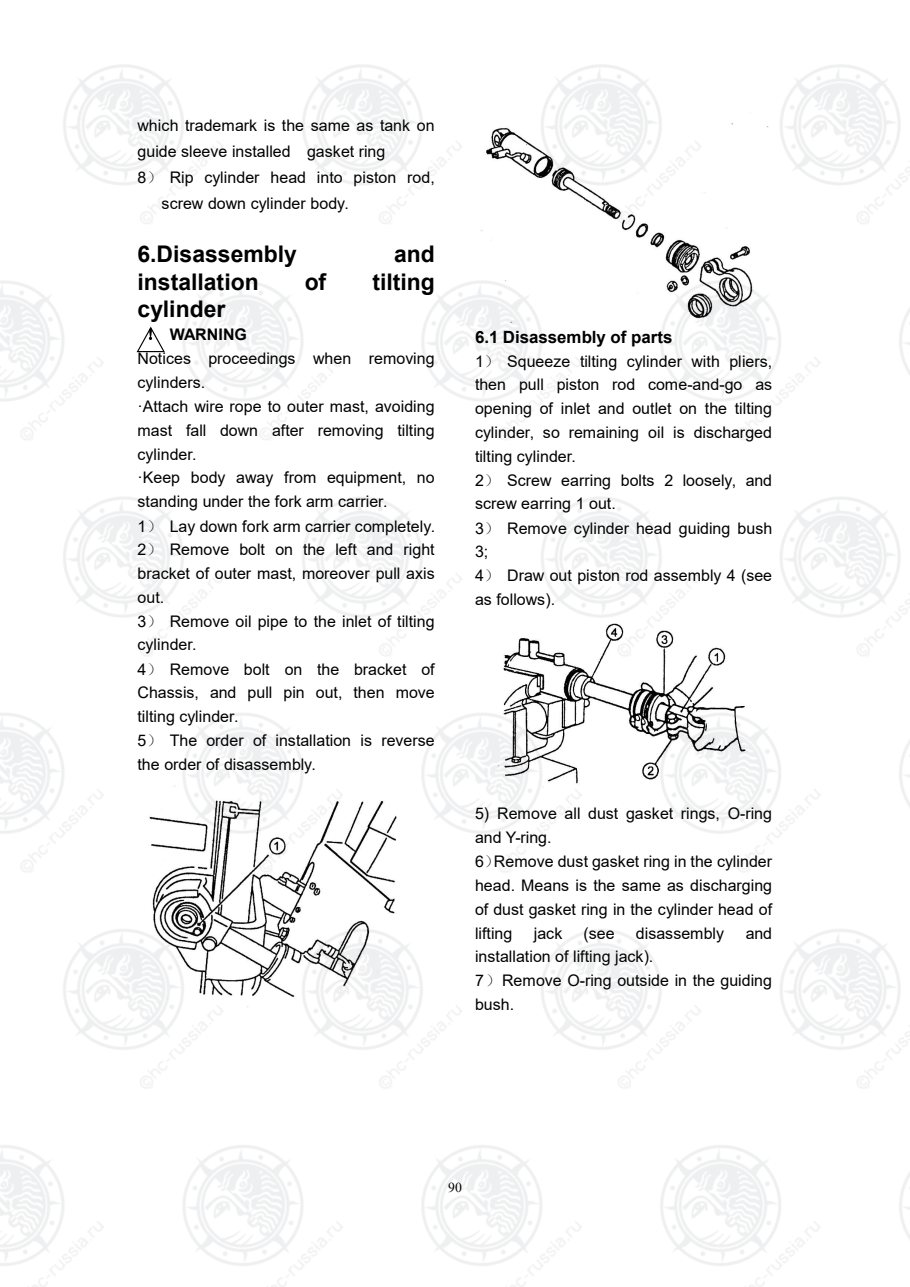
Страница 96
91
8) Remove O-ring and Y-ring in the inner
hole of guiding bush (see Fig.
disassembly and installation of lifting
jack).
CAUTION:No using dust gasket ring and
Y-ring removed.
6.2 Install tilting cylinder after replacing
ring
The order of installation is reverse to the
order of disassembly, but should notice
follow proceedings:
1) Lubricate parts with clean hydraulic
pressure oil.
2) Avoid dust and oil dirty dropping into
tilting cylinder.
3) Avoid scratching the end of cylinder
body, and inlet and outlet for oil.
4) Push piston rod to cylinder body
when setting center, especially avoid
scratching Y-ring.
5) Before installing guiding bush, wipe
hydraulic pressure oil backing boardched
with employment oil trademark in the
middle of O-ring and Y-ring in the inner
hole of guiding bush.
6) Don’t scratch O-ring outside in the
guiding bush when installing.
7) Remember install nylon stopper and
tighten screw after screw cylinder head.
7. Noticing proceeding of
debugging
1) Adjust Forward and Backward of the
mast
Place fork lift truck on the level ground,
operate control lever to realize that mast
inclined forward or backward extremely.
As assembly debugging data required,
adjust combined screw thread length till
according with data of Backward. Then
lock earring ring close. ( please see
foregoing table if you want know
tightening torque of M10 bolt)
2) Adjust installation position of left and
right lifting jack again
a. Adjust washer in the middle of piston
rod and inner mast bracket if one lifting
jack is not synchronization with the others
when rising or falling, and if one lifting jack
is different height from the others.
b. Loose two nuts on the U-bolt. Mast is
not rise and lower until relative position of
U-bolt and lifting jack is suitable. Then
screw down nuts and tightening screw on
the U-bolt. Thus lifting jack can be used
longer and wear of piston rod can be
reduced.
3) Please see foregoing table if you
want know tightening force of bolt or
screw. Please refer to common bolt
tightening torque prescribed in our
company if you want know other
tightening force of bolt or screw.(refer to
OPERATION AND MAINTAIN MANUAL backing
boardched with it).
Оригинальная страница: таблицы и схемы
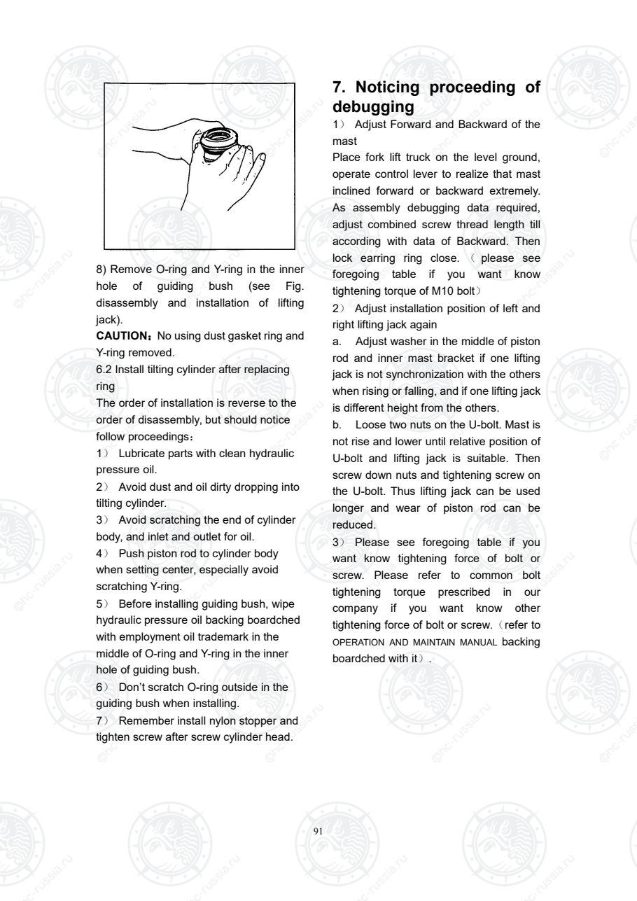
Страница 97
92
Ⅶ.Electrical system
Warning
Before checking any parts of electrical system, remove rings and jewelry to prevent
short circuit, and turn off ignition switch and then disconnect battery ground cable.
Before doing any electrical maintenance, make sure battery cable has been
disconnected.
Description
Cables are covered with color-coded vinyl for easy identification. In the wiring diagram, colors are
indicated by one or two alphabetical letters. Their meanings are as follows:
Letter B N G U O R W Y S P B/W G/Y
Meaning Black Brown Green Blue Orange Red White Yellow Grey Purple Black
white
Green
yellow
Inspect
Inspect all electrical circuit, referring to wiring diagrams. Circuits should be tested for continuity or
short circuit with a conventional test lamp or circuit tester. Before inspecting circuit, ensure that:
– Each electrical component part or cable is securely fastened to its connector or terminal.
– Each connection is firmly in place and free from rust and dirt.
– No cable covering shows any evidence of cracks, deterioration or other damage.
– Each terminal is a safe distance away from any adjacent mental parts.
– Each cable is fastened to its proper connector or terminal.
– Wiring is kept away from any adjacent parts with sharp edges.
– Wiring is kept away from any rotating or moving parts.
– Cables between fixed portions and moving parts are long enough to withstand shocks and
vibrations.
– The wiring keeps a safety distance with the high temperature thing such as the vent-pipe.
Оригинальная страница: таблицы и схемы
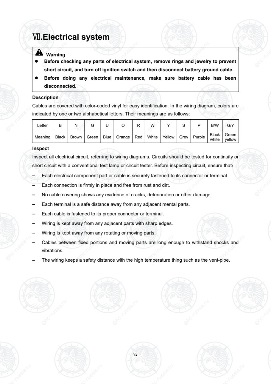
Страница 98
93
1 Control box assembly
Component removal
– Turn key switch "OFF";
– Press lock buckle on control box and open the cover;
– Remove fuse and relay from box.
Explanation
If fuse or relay is broken, replace with new one.
①If fuse is damaged, be sure to eliminate cause of problem before installing new fuses.
②Never use fuse higher than specified rating.
Оригинальная страница: таблицы и схемы
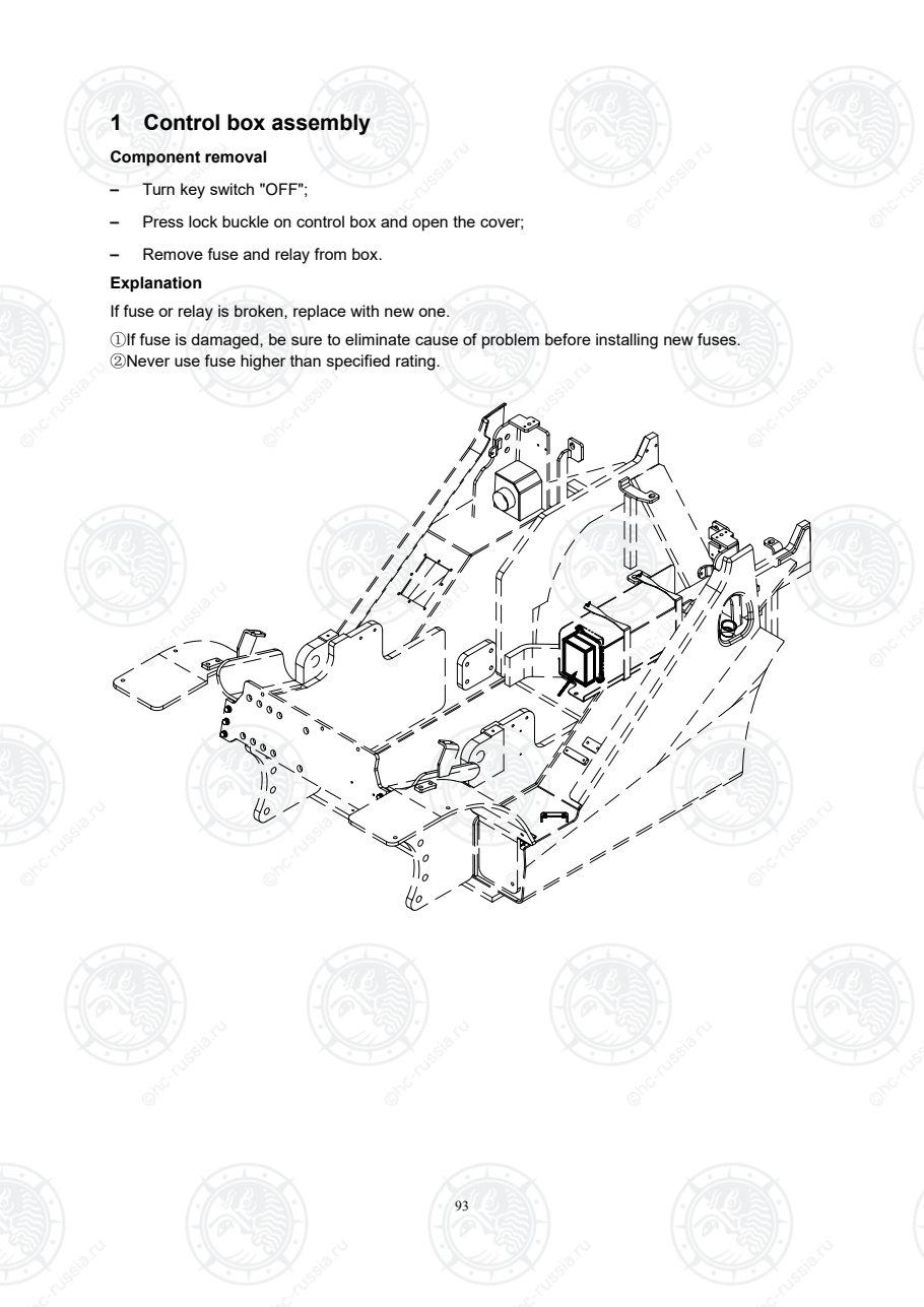
Страница 99
94
2 Instrument, sensor and relay
Combination instrument assembly
– Remove 4 fixed bolts from meter case. Notice that when installing and removing, please make
instrument surface tilt an angle to avoid damaging the screw thread of fixed parts on truck.
– Take out wiring harness from sleeve, and then instrument can be brought out.
– There is transparent plastic cover to cover, so it can prevent dust and water, and it is fixed by 6
plastic clip buckles, please press down plastic buckles lightly to take out plastic cover when
removing.
– To install, reverse removal procedures.
Оригинальная страница: таблицы и схемы
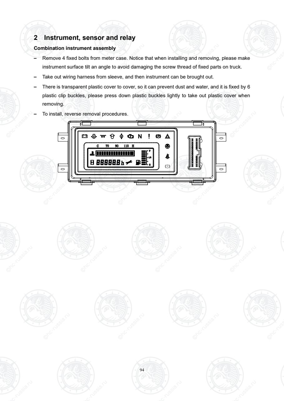
Страница 100
95
Key (start) switch
Disassemble and install
– Remove combination meter.
– Disconnect connector of wring.
– Remove nuts, washers, spacers and instrument plate.
To install, reverse removal procedures.
Adjust ledge of switch to proper length when installing.
Inspect
Use multimeter (with ohm) to check key switch whether it is on at each position.
Switch position Terminal
OFF OFF
ON B1-B2-Acc on
START B1-B2-Acc-C-R2 on
Principle diagram of preheat start switch
Connection point
Position B1 B2 Acc C R1 R2
Preheat O O O
Close O O
Run O O O
Start O O O O
Backup buzzer disassemble and install
– Remove the wiring terminal, then unscrew the bolt.
To install, reverse removal procedure
Horn disassemble and install
– Disconnect horn harness connector.
– Remove bolt and horn.
To install, reverse removal procedure.
Оригинальная страница: таблицы и схемы
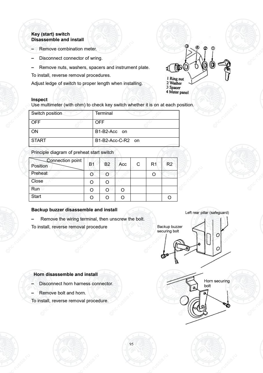
Страница 101
96
3 Lighting system
Bulb specification
Forklift truck W57 engine Except W57 engine
Bulb Wattage
Headlamp 9V-36V, 15W
Front small lamp
Turn signal lamp
width guide lamp
12V-21W
12V-10W
24V-21W
24V-10W
Assembled back lamp
Brake signal lamp
width guide lamp
Turn signal lamp
reversing lamp
12V-21W/5W
12V-21W/5W
12V-21W
12V-10W
24V-21W/5W
24V-21W/5W
24V-21W
24V-10W
Assembled instrument
Head lamp
Warn-up lamp
12V-2W
12V-2W
24V-2W
24V-2W
Location of light
Оригинальная страница: таблицы и схемы
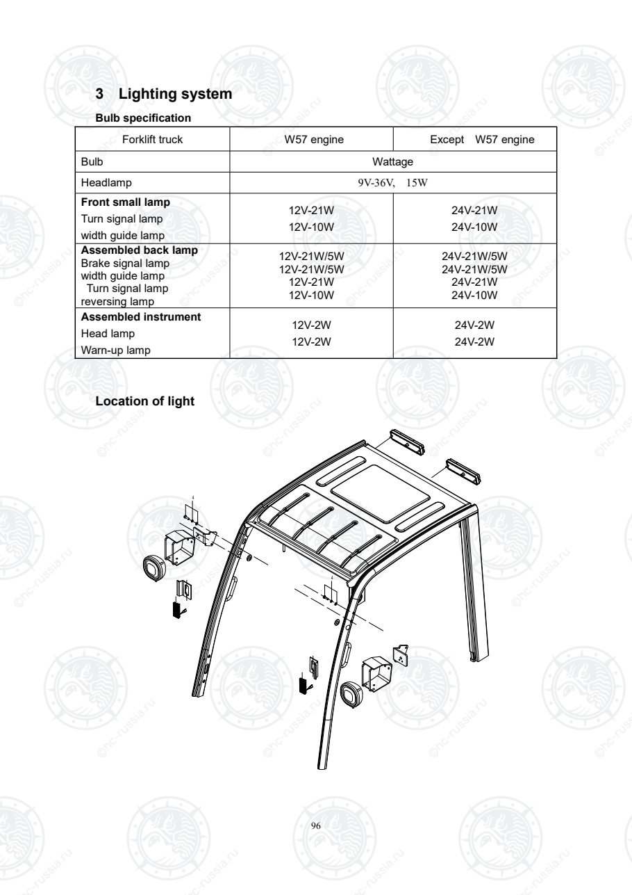
Страница 102
97
Front headlight
Disassembly
1.Remove securing nuts of the big-little lamp.
2.Take apart the wiring connector.
3. Remove bolt、lens, then replace faulty
LED with new one.
7) Assembly is the opposite procedures.
Front combination lamp
Disassembly and assembly
1.Remove fixing bolt of bracket.
2.Disconnect the wiring connector.
3.Remove bolt、astigmatism glass, then replace faulty LED with new one.
4. Assembly is the opposite procedures.
Оригинальная страница: таблицы и схемы
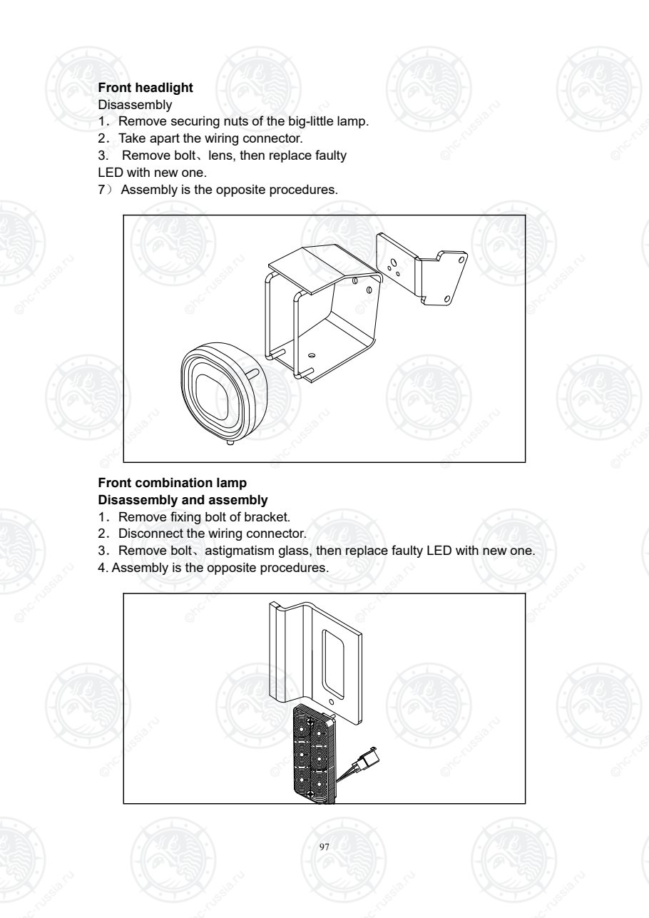
Страница 103
98
Disassembly and installation of rear combination lamp
– Take down rear combination lamp from overhead guard;
– Bring the whole rear combination lamp to maintain location, remove rear lamp cover,
and remove 4 bolts from back of cover;
– Remove LED penal , loosen 2 bolts from fixed connector, disconnect connector,
replace new LED panel
– To install, reverse removal procedures.
Direction switch
Disassemble
1.Remove combined switch
2. Unscrew the screws, and disconnect
the wiring connector.
To install, reverse the order of removal.
F1—Forward 1 gear
F2—Forward 2 gears
R—Reverse gear
Direction switch check
– Disconnect switch connector clip, and check if each point is connected.
– Use multimeter (with ohm) to inspect whether each position is connected: F1, F2, N,
R.
Оригинальная страница: таблицы и схемы
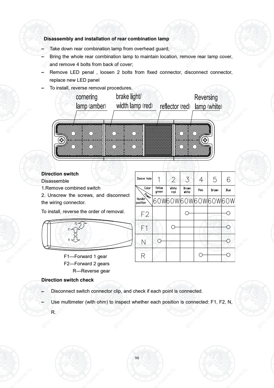
Страница 104
99
Position Contact
F1 2—6
F2 3—6
N 1—6
R 4—6
Light switch Turn signal switch
Dismantle
29. Dismantle combination instrument.
30. Unscrew screw, disconnect wiring
connector
To install, reverse removal procedure
Turn light check
– Use multimeter(with ohm) to inspect whether it is on when turn light switch is on these
positions: left turn, N, right turn.
Position Contact
Left turn 1-2
N OFF
Right left 1-3
Inspect lighting switch
Power
Оригинальная страница: таблицы и схемы
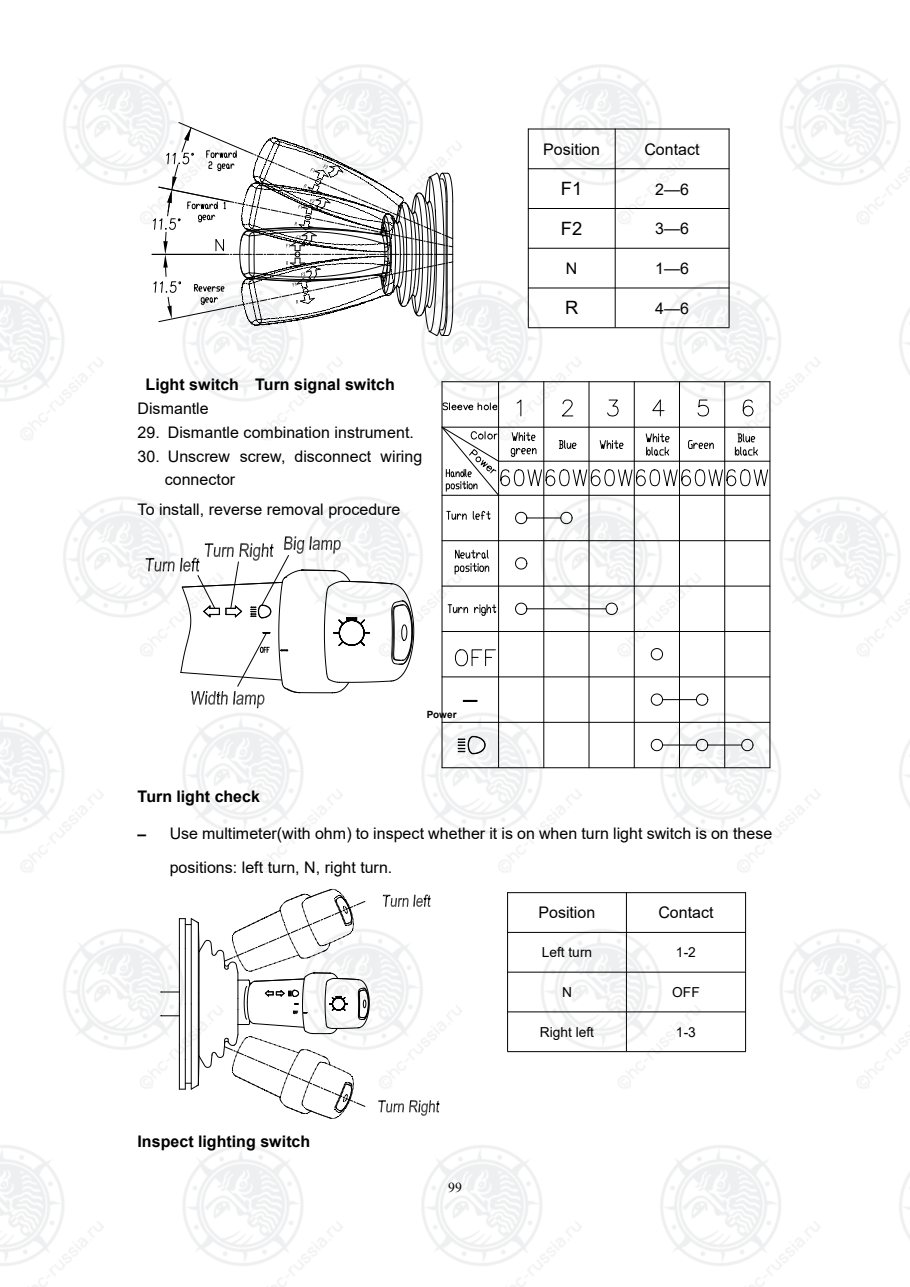
Страница 105
100
– Disconnect switch connector, and check whether each connection point is on.
– Use multimeter (with ohm) to inspect whether it is on when lighting switch is on these
positions: head lamp, width lamp, OFF.
Position Contact
Head lamp 4-6
Width lamp 4-5
OFF OFF
Оригинальная страница: таблицы и схемы
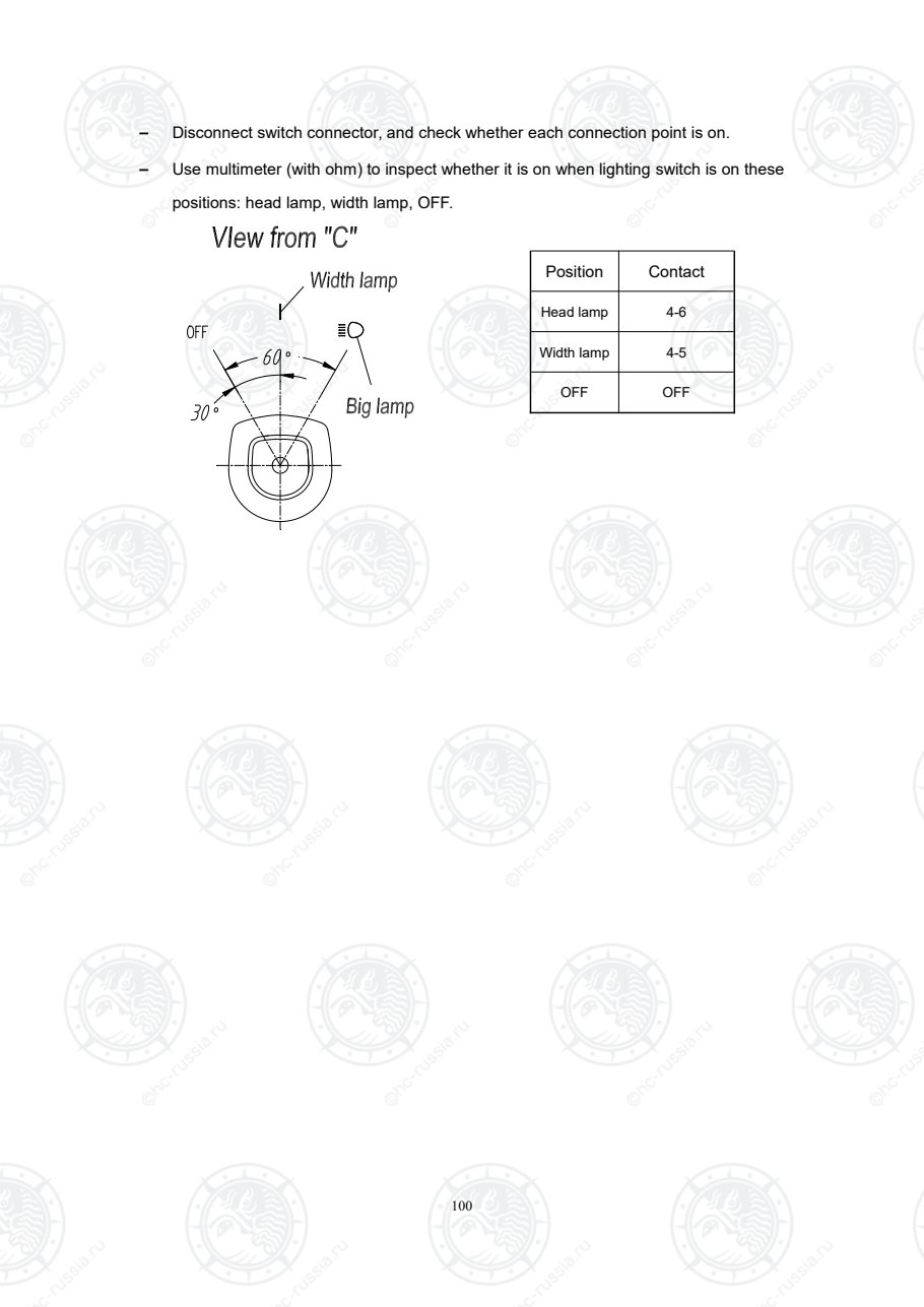
Страница 106
start and preheat are short
working,automatically return.
Fig.1-1 CPCD40/45-XRG76,CPCD50-XRXG76 Electrical system diagram
Оригинальная страница: таблицы и схемы
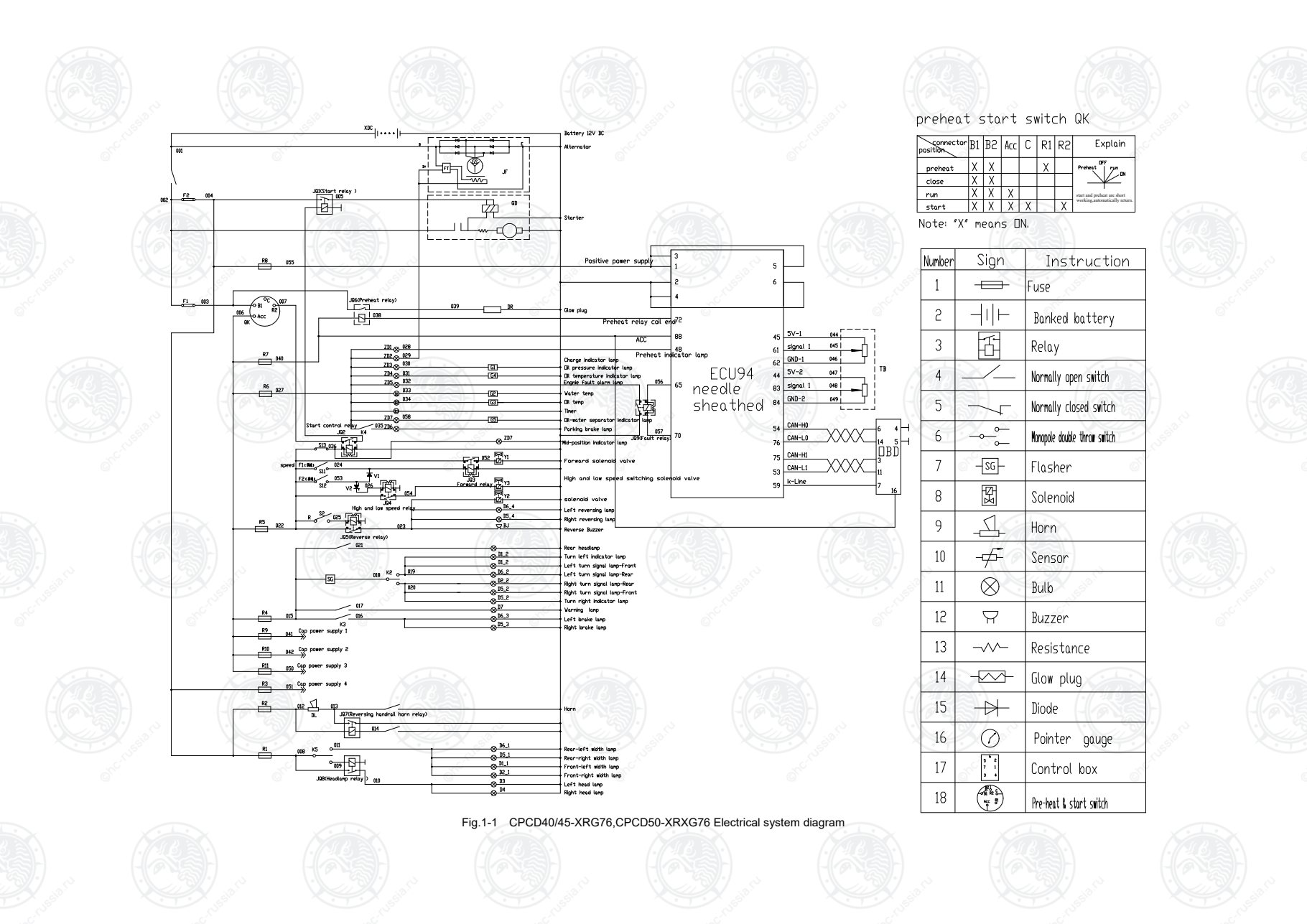
Страница 107
102
start and preheat are short
working,automatically return.
Fig.1-2 CPC40/45-XRG76,CPC50-XRXG76 Electrical system diagram
Оригинальная страница: таблицы и схемы
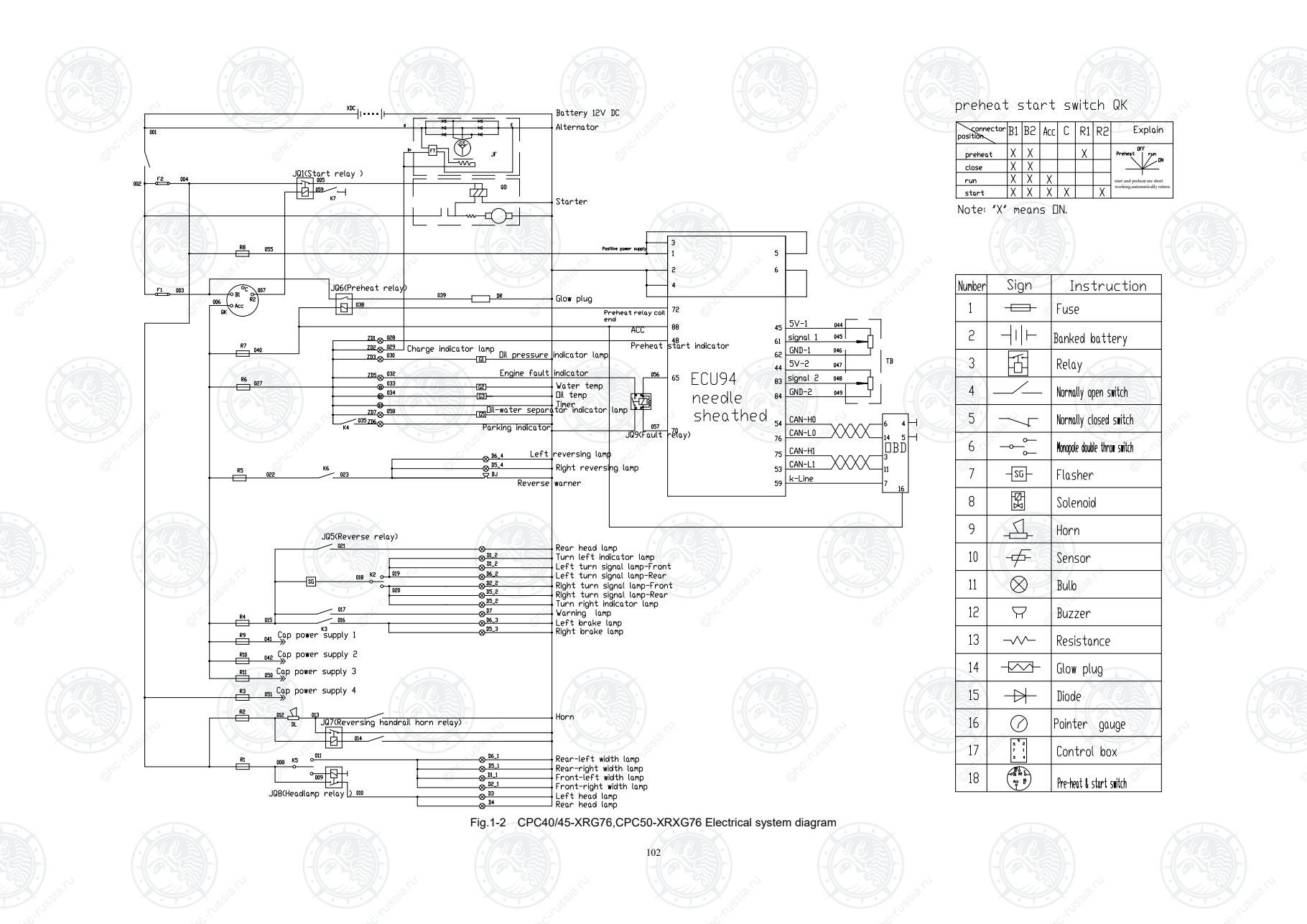
Страница 108
103
start and preheat are short
working,automatically return.
Fig.2-1 CPCD40/45-XRG75,CPCD50-XRXG75,CPCD40/45-XRG75-GW,CPCD50-XRXG75-GW Electrical system diagram
Оригинальная страница: таблицы и схемы
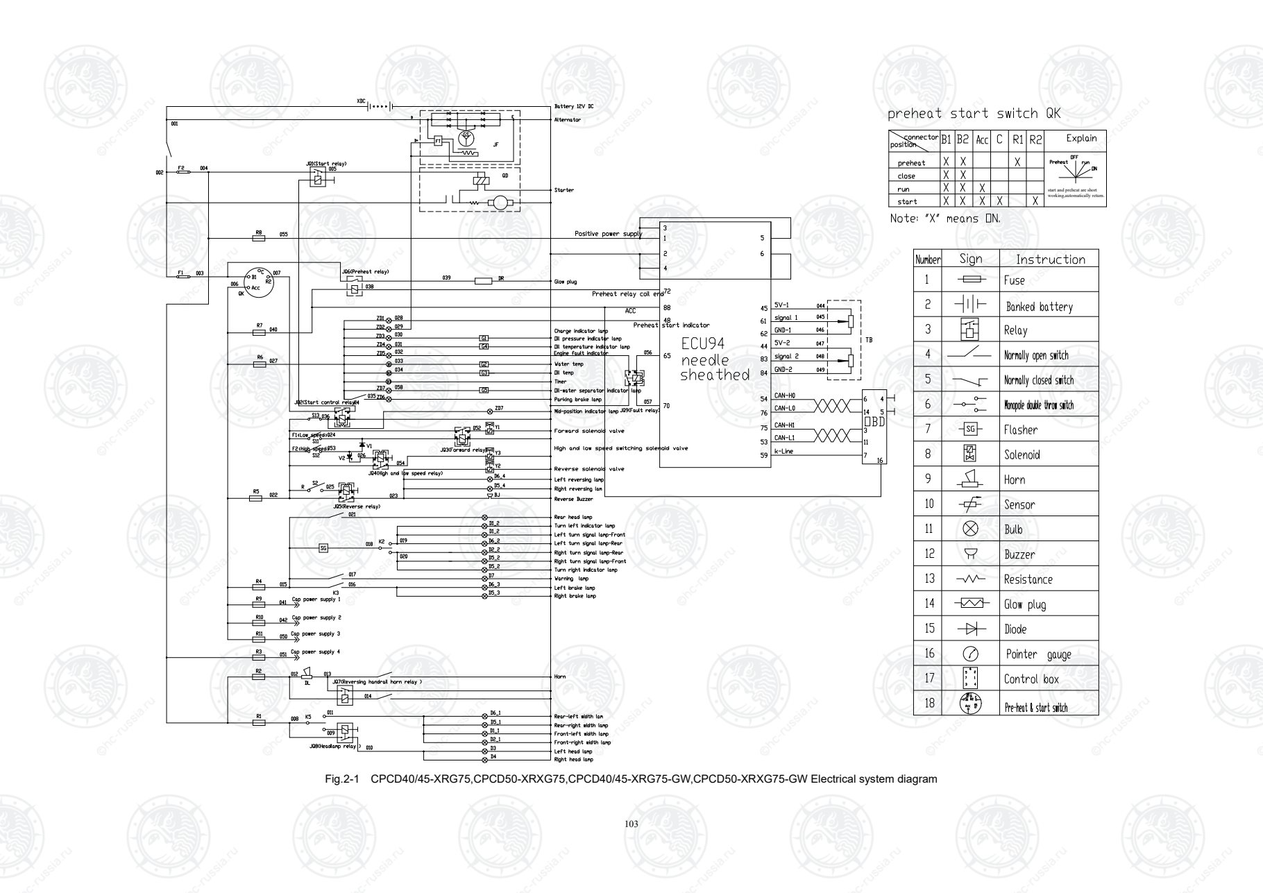
Страница 109
104
start and preheat are short
working,automatically return.
Fig.2-2 CPC40/45-XRG75, CPC50-XRXG75 Electrical system diagram
Оригинальная страница: таблицы и схемы
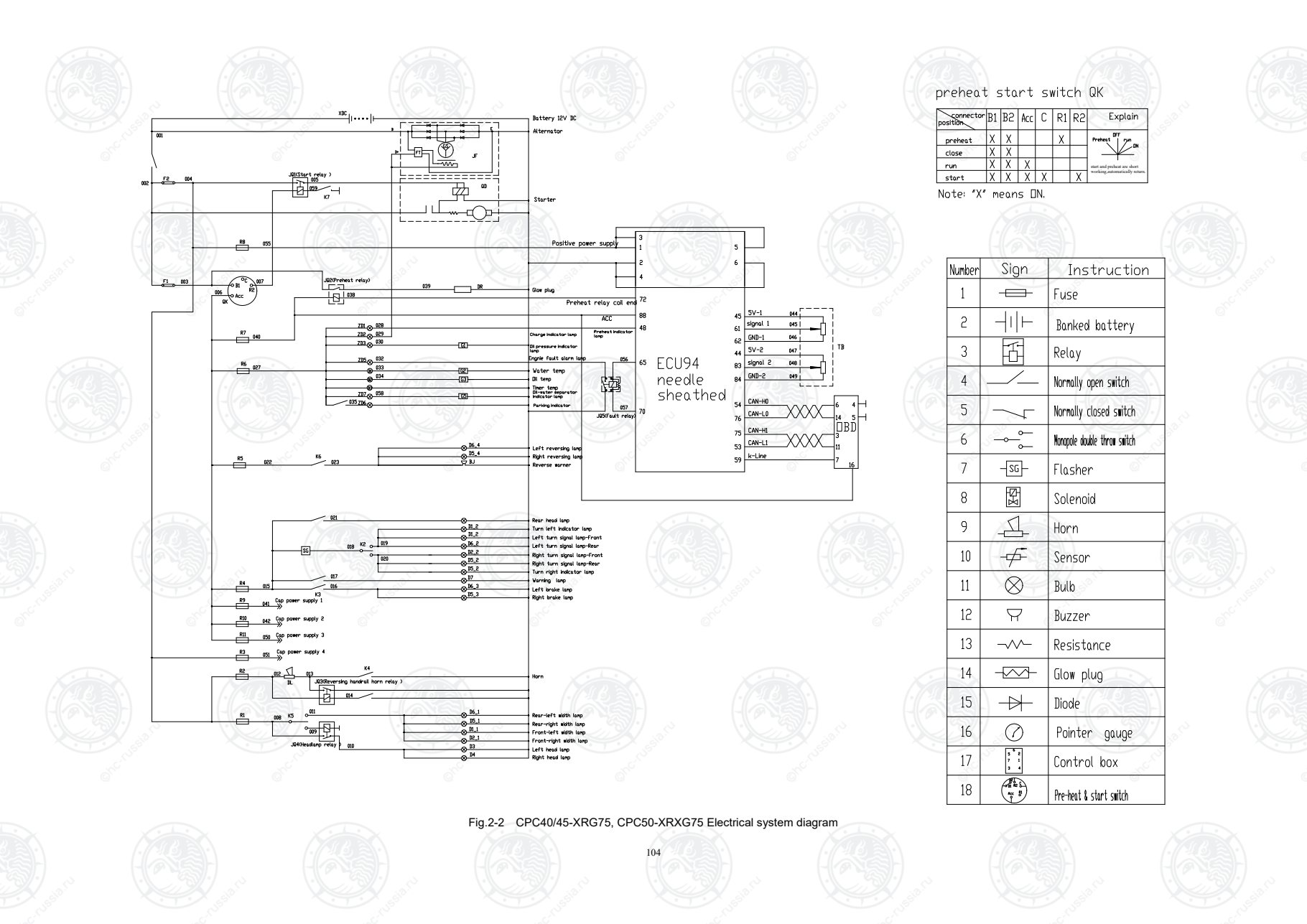
Страница 110
105
start and preheat are short
working,automatically return.
Fig.3 CPCD40/45-XRW35,CPCD50-XRXW35, CPCD40/45-XRW34,CPCD50-XRXW34 Electrical system diagram(without OPS)
Оригинальная страница: таблицы и схемы
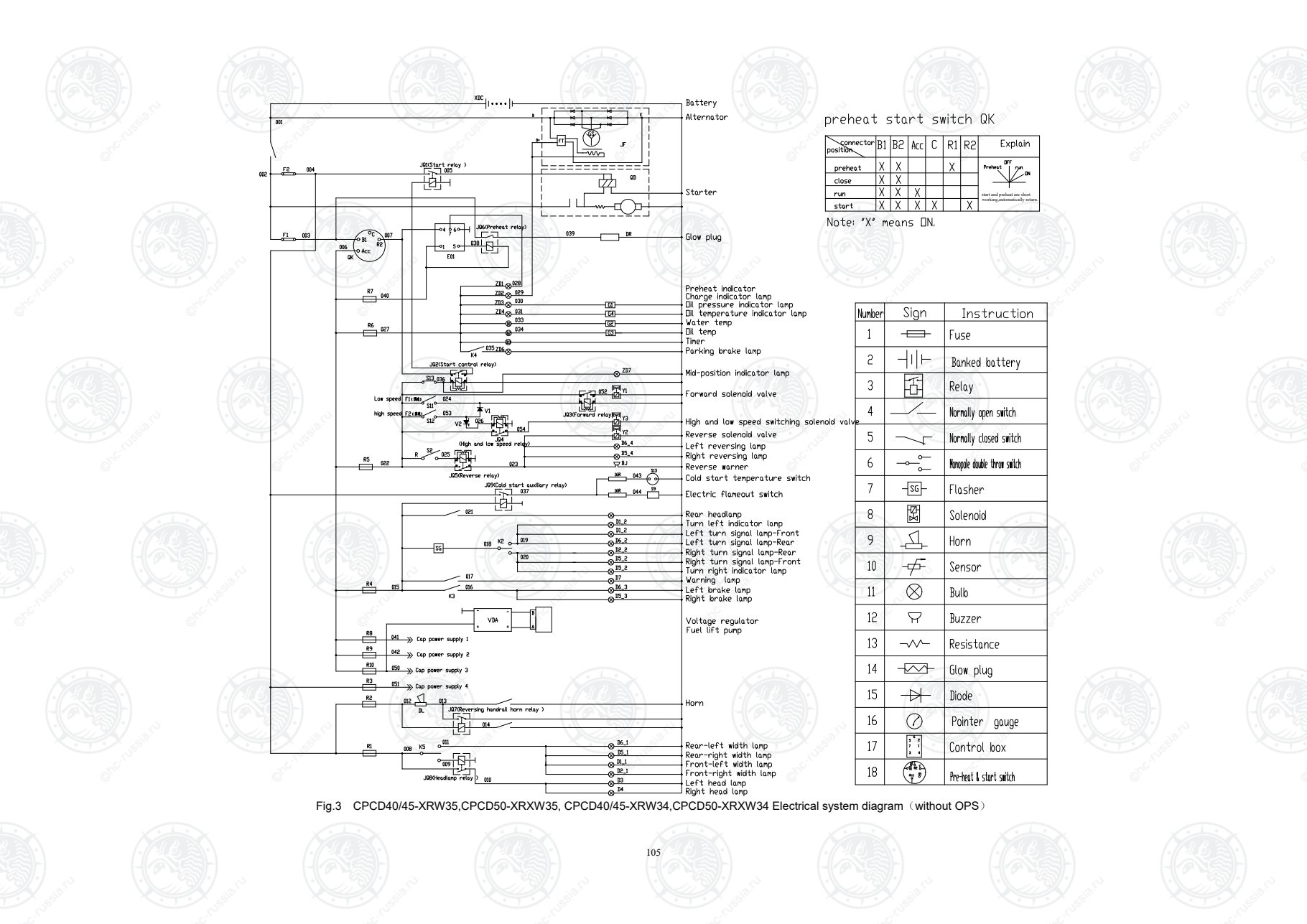
Страница 111
106
Fig.3-1 CPCD40/45-XRW35,CPCD50-XRXW35 Electrical system diagram(with OPS)
Оригинальная страница: таблицы и схемы
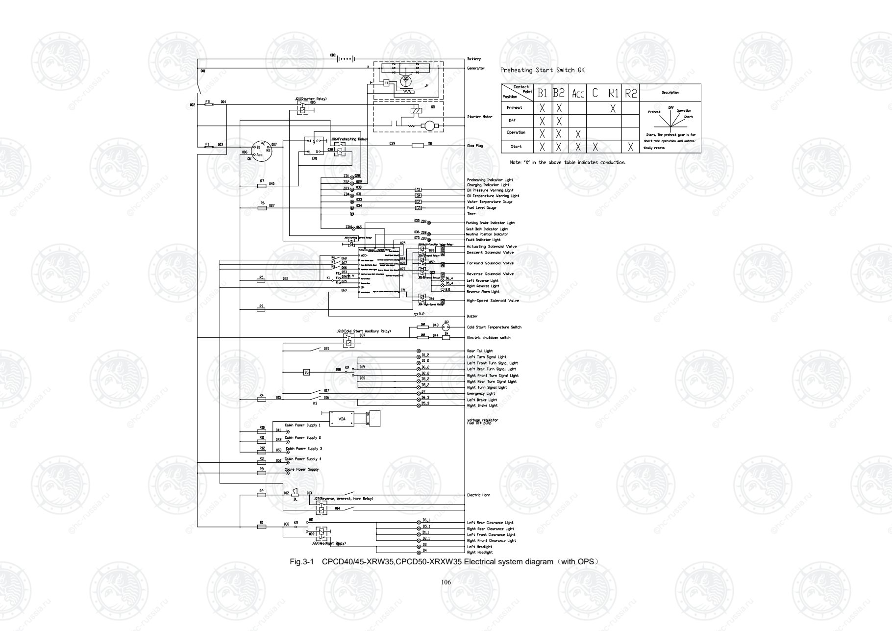
Страница 112
107
NO. Symbol Name QTY Remarks
1 XDC Less maintenance of battery 12V 60Ah 2
2 JF generator -1 Engine matching
3 QD starter -1 Engine matching
4 QK Preheat Starter Switch -1 Combination instrument matching
5 K1 Combination switch (direction switch) 1
6 K2 Combination switch (turn signal switch) 1
7 K3 brake light switch 1
8 K4 Horn button -1 Steering wheel matching
9 K5 Combination switch (light switch)
10 B1 Water temperature gauge 24V -1 Combination instrument matching
11 B2 Oil gauge 24V -1 Combination instrument matching
12 B3 Timer 24V -1 Combination instrument matching
13 ZD1-ZD5 Alarm light 24V 2W -5 Combination instrument matching
14 G1 Oil pressure alarm -1 Engine matching
15 G2 Water Temperature Sensor -1 Combination instrument matching
16 G3 Oil quantity sensor -1 Combination instrument matching
17 G4 Oil temperature alarm 1
18 D1 D2 Front small light 21W 10W 2
19 D3 D4 Front headlight 15W 2
20 D5 D6 Combination rear light 21W21W/5W10W 2
21 DR GLOW PLUG -1 Engine matching
22 E01 Preheating timer 24V -1 Control box matching
23 BJ Reverse alarm 24V 1
24 DL Electric horn 24V 1
25 SG Flasher 24V 1 Control box matching
26 JQ1 Starting relay 24V 1 Control box matching
27 JQ2 Starting control relay 24V 1 Control box matching
28 JQ3 Forward relay 24V 1 Control box matching
29 JQ4 High speed relay 24V 1 Control box matching
30 JQ5 Reverse gear relay 24V 1 Control box matching
31 JQ6 Preheating relay 24V 1 Control box matching
32 JQ7 Reverse armrest horn relay 24V 1 Control box matching
33 JQ8 Headlight relay 24V 1 Control box matching
34 JQ9 Multi way valve relay 24V 1 Control box matching
35 JQ10 Cold start auxiliary relay 24V 1 Control box matching
36 R1-R12 fuse 1 Control box matching
37 F1-F2 fuse 1
Fig.3-2 CPCD40/45-XRW35,CPCD50-XRXW35 Electrical system diagram(with OPS)
Оригинальная страница: таблицы и схемы
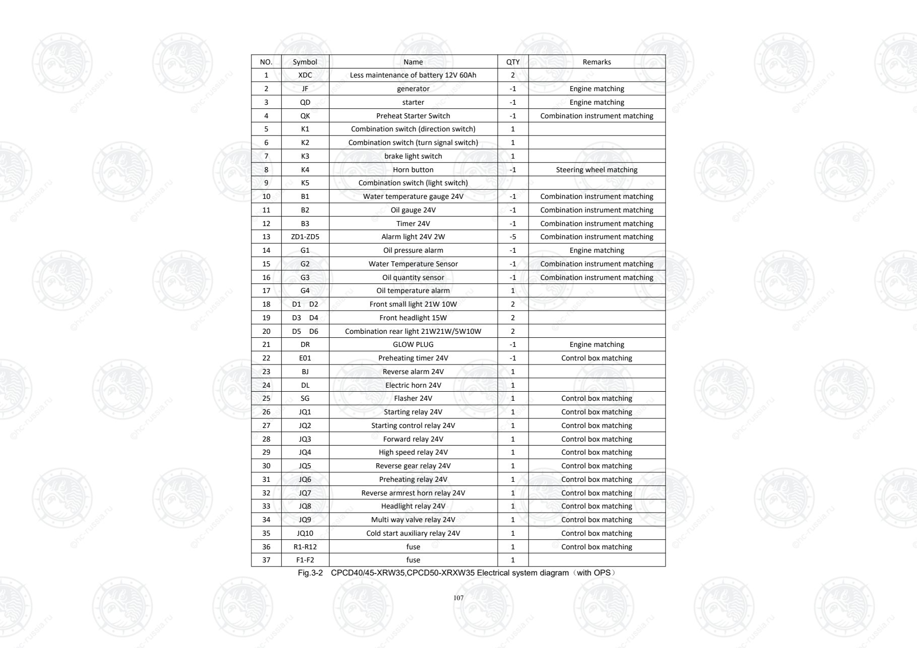
Страница 113
108
start and preheat are short
working,automatically return.
Fig.4 CPQYD40/45-XRW57, CPQYD50-XRXW57 Electrical system diagram(without OPS)
Оригинальная страница: таблицы и схемы
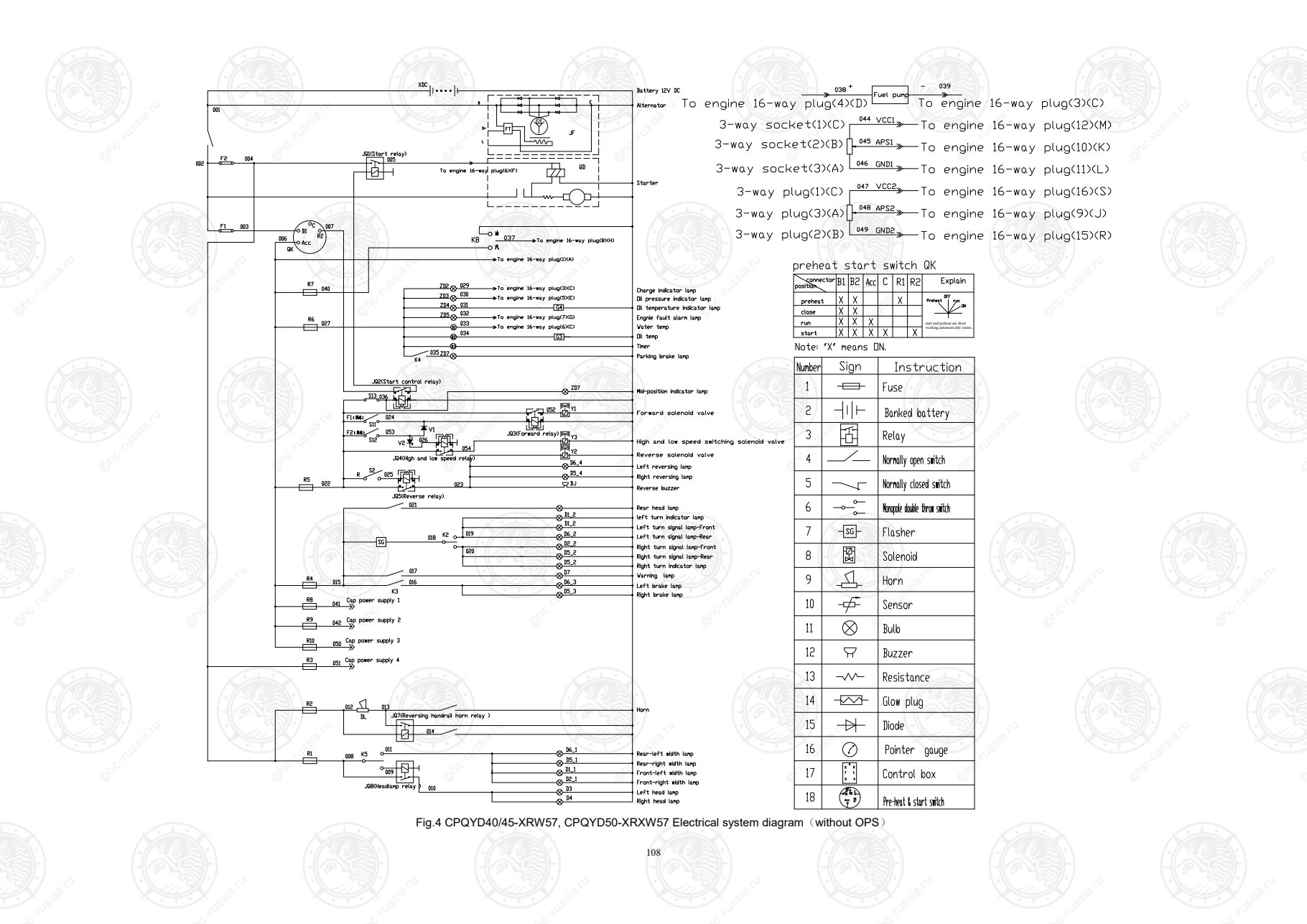
Страница 114
109
Fig.4-1 CPQYD40/45-XRW57, CPQYD50-XRXW57 Electrical system diagram(with OPS)
Оригинальная страница: таблицы и схемы
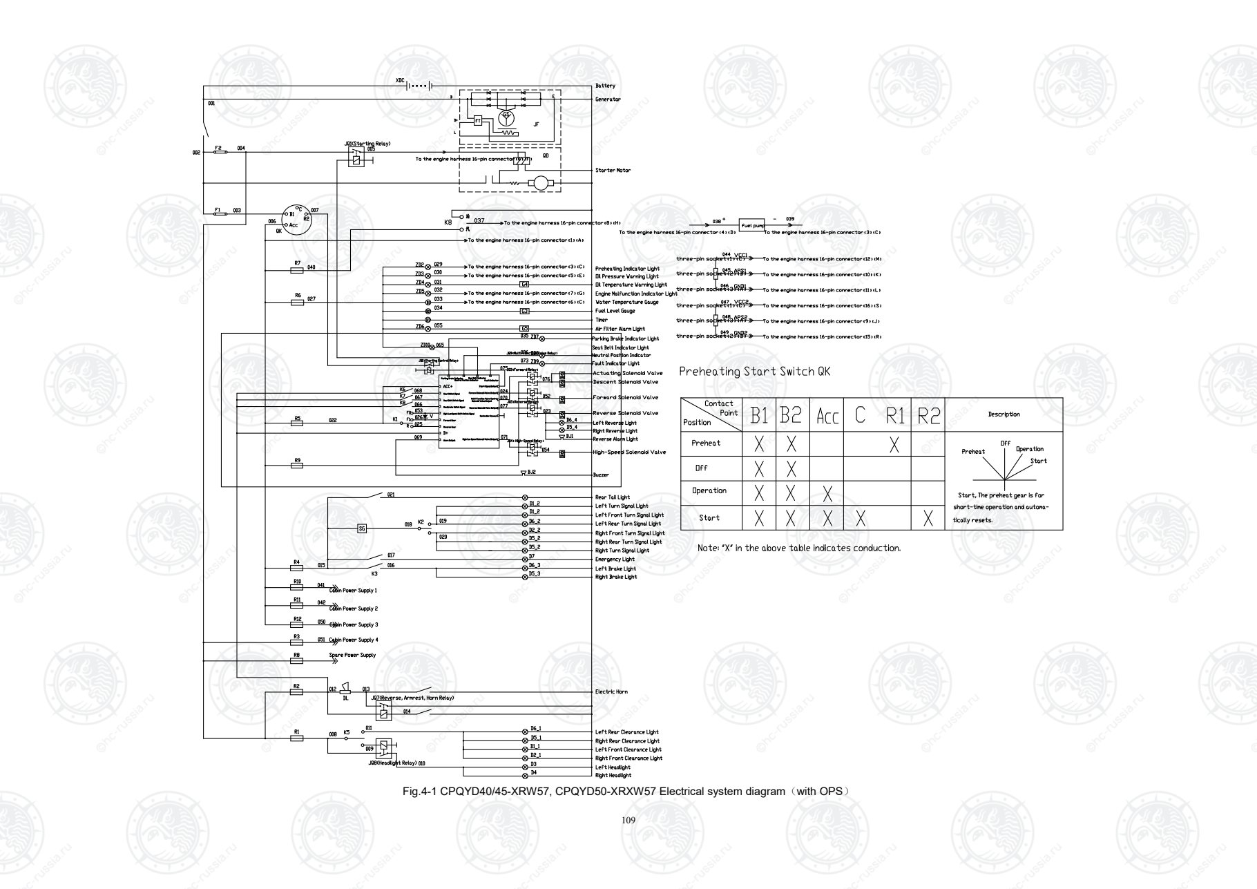
Страница 115
110
NO. Symbol Name QTY Remarks
1 XDC Less maintenance of battery 12V 60Ah 1
2 JF generator -1 Engine matching
3 QD starter -1 Engine matching
4 QK Preheat Starter Switch -1 Combination instrument matching
5 K1 Combination switch (direction switch) 1
6 K2 Combination switch (turn signal switch) 1
7 K3 brake light switch 1
8 K4 Horn button -1 Steering wheel matching
9 K5 Combination switch (light switch)
10 B1 Water temperature gauge 12V -1 Combination instrument matching
11 B2 Fuel gauge 12V -1 Combination instrument matching
12 B3 Timer 12V -1 Combination instrument matching
13 ZD1-ZD5 Alarm light 12V 2W -5 Combination instrument matching
14 G3 Fuel quantity sensor -1 Engine matching
15 G4 Oil temperature alarm 1
16 G5 Air filter alarm switch 1
17 D1 D2 Front small light 21W 10W 2
18 D3 D4 Front headlight 15W 2
19 D5 D6 Combination rear light 21W/21W/5W/10W 2
20 BJ Reverse alarm 12V 1
21 DL Electric horn 12V 1
22 SG Flasher 12V 1 Control box matching
23 JQ1 Starting relay 12V 1 Control box matching
24 JQ2 Starting control relay 12V 1 Control box matching
25 JQ3 Forward relay 12V 1 Control box matching
26 JQ4 High speed relay 12V 1 Control box matching
27 JQ5 Reverse gear relay 12V 1 Control box matching
28 JQ6 Preheating relay 12V 1 Control box matching
29 JQ7 Reverse armrest horn relay 12V 1 Control box matching
30 JQ8 Headlight relay 12V 1 Control box matching
31 JQ9 Multi way valve relay 12V 1 Control box matching
32 R1-R12 fuse 1 Control box matching
33 F1-F2 Easy fuse 1
Fig.4-2 CPQYD40/45-XRW57, CPQYD50-XRXW57 Electrical system diagram(with OPS)
Оригинальная страница: таблицы и схемы
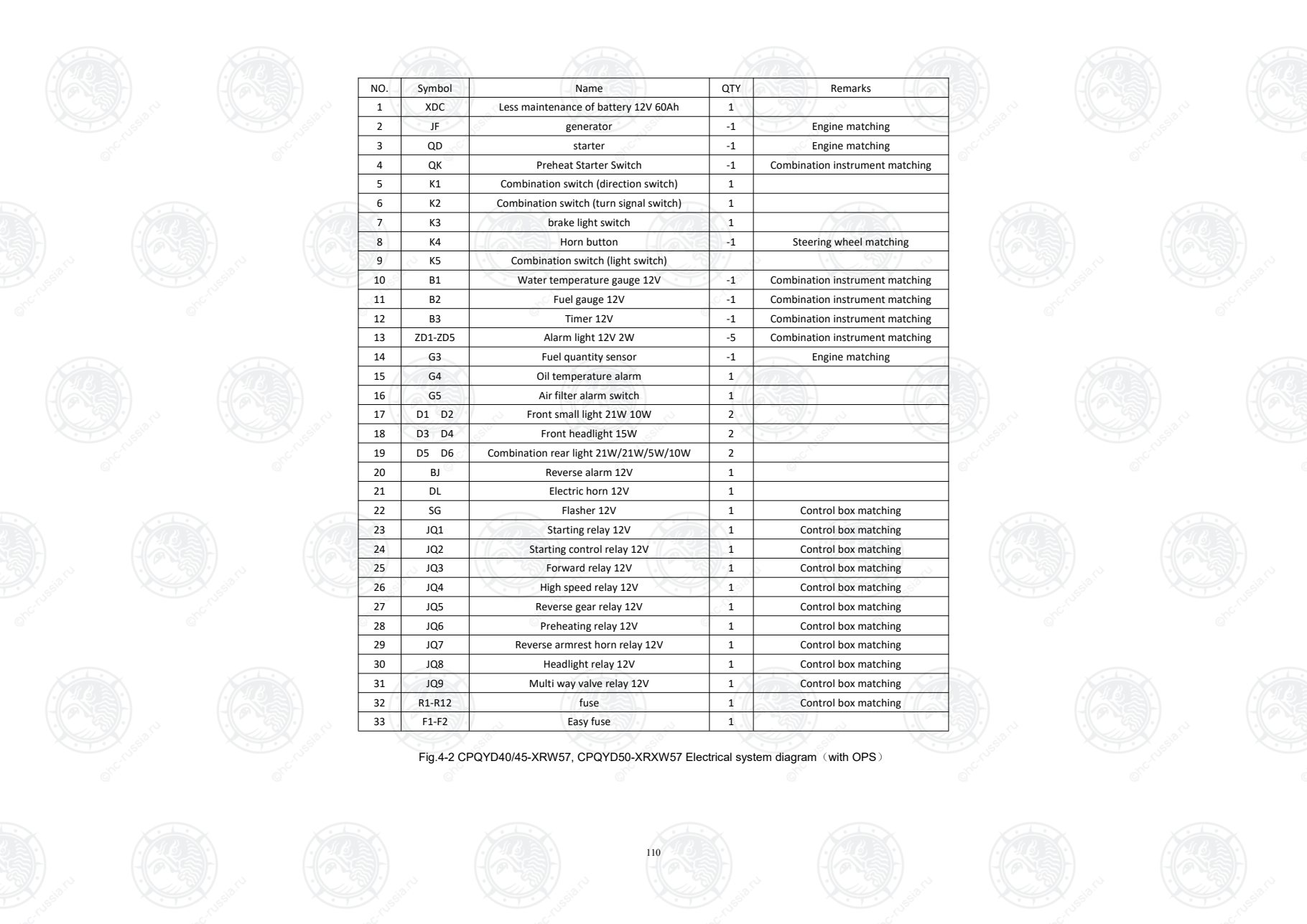
Страница 116
111
start and preheat are short
working,automatically return.
Number Sign Instruction
Fuse
Banked
battery
Battery 12V DC
Alternator
Starter
Glow plug
Preheat indicator lamp
Charge indicator lamp
Oil pressure indicator lamp
Oil temperature indicator lamp
Engine fault indicator
Timer
Oil-water separator indicator lamp
neutral indicator
Forward solenoid valve
High and low speed
switching solenoid valve
Reverse solenoid valve
Left reversing lamp
Right reversing lamp
Reversing buzzer
Rear headlight
Turn left indicator lamp
Left turn signal lamp-Front
Left turn signal lamp-Rear
Right turn signal lamp-Front
Right turn signal lamp-Rear
Turn right indicator lamp
Warning  lamp
Left brake lamp
Right brake lamp
Horn
Rear-left width lamp
Rear-right width lamp
Front-left width lamp
Front-right width lamp
Left head lamp
Right head lamp
Fig.6-1 CPCD40/45-XRG73, CPCD50-XRXG73 Electrical system diagram
Оригинальная страница: таблицы и схемы
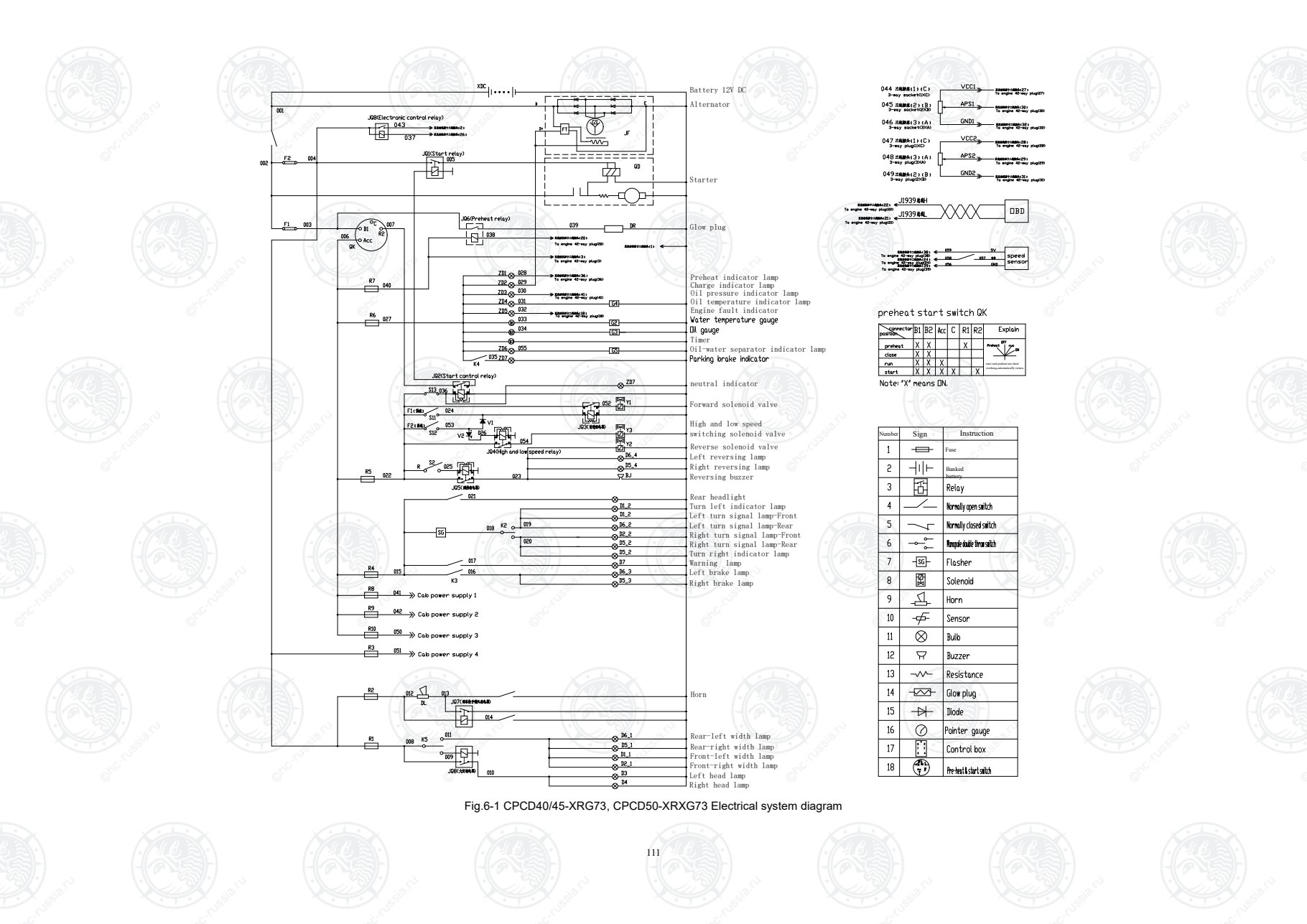
Страница 117
112
Rear-right width lamp
Front-left width lamp
Front-right width lamp
Left head lamp
Right head lamp
Engine fault indicator
Timer
Oil-water separator indicator lamp
Left reversing lamp
Right reversing lamp
Rear headlight
Turn left indicator lamp
Left turn signal lamp-Front
Left turn signal lamp-Rear
Right turn signal lamp-Front
Right turn signal lamp-Rear
Turn right indicator lamp
Warning  lamp
Left brake lamp
Right brake lamp
Horn
Rear-left width lamp
Battery 12V DC
Alternator
Starter
Glow plug
Preheat indicator lamp
Charge indicator lamp
Oil pressure indicator lamp
start and preheat are short
working,automatically return.
Number Sign Instruction
Fuse
Banked
battery
Fig.6-2 CPC40/45-XRG73, CPC50-XRXG73 Electrical system diagram
Оригинальная страница: таблицы и схемы
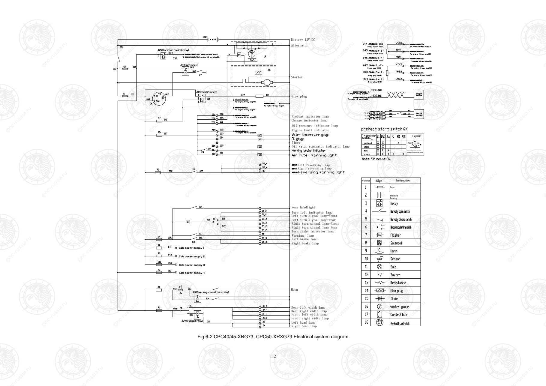
Страница 118
113
start and preheat are short
working,automatically return.
Fig.7 CPCD40/45-XRW76, CPCD50-XRXW76 Electrical system diagram(without OPS)
Оригинальная страница: таблицы и схемы
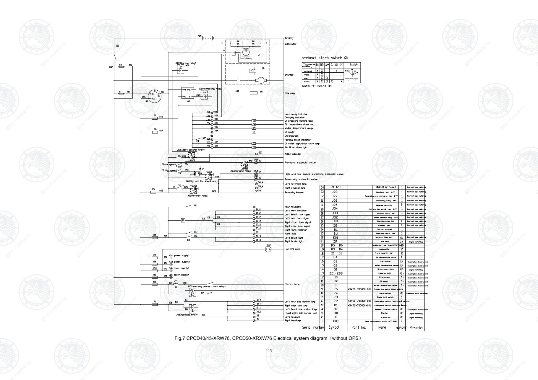
Страница 119
114
start and preheat are short
working,automatically return.
Fig.8 CPCD40/45-XRW76BN, CPCD50-XRXW76BN Electrical system diagram(without OPS)
Оригинальная страница: таблицы и схемы
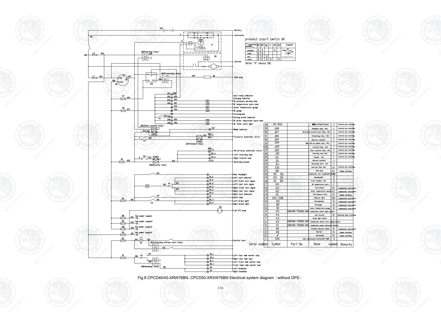
Страница 120
115
Right headlamp
Left headlamp
Front right side lamp
Left front side lamp
Right rear side lamp
Rear left side marker lamp
Electric horn
start and preheat are short
working,automatically return.
Right brake light
Left brake light
Alarm lamp
Right turn indicator
Right rear turn signal
Right front turn signal
Rear left turn signal
Left front turn signal
Left turn indicator
Rear headlight
Reversing warning lamp
Right reverse lamp
Left reverse lamp
Reverse solenoid valve
Forward solenoid valve
Middle indicator
Oil temperature warning lamp
Oil pressure warning lamp
Charging indicator
heat ready indicator
Water temperature gauge
Engine fault indicator
Oil water separation warning lamp
Fuel gauge
Chronograph
Parking brake indicator
Starter
Alternator
Battery
Glow plug
Fig.9 CPCD55-XRXG73BN-S Electrical system diagram
Оригинальная страница: таблицы и схемы
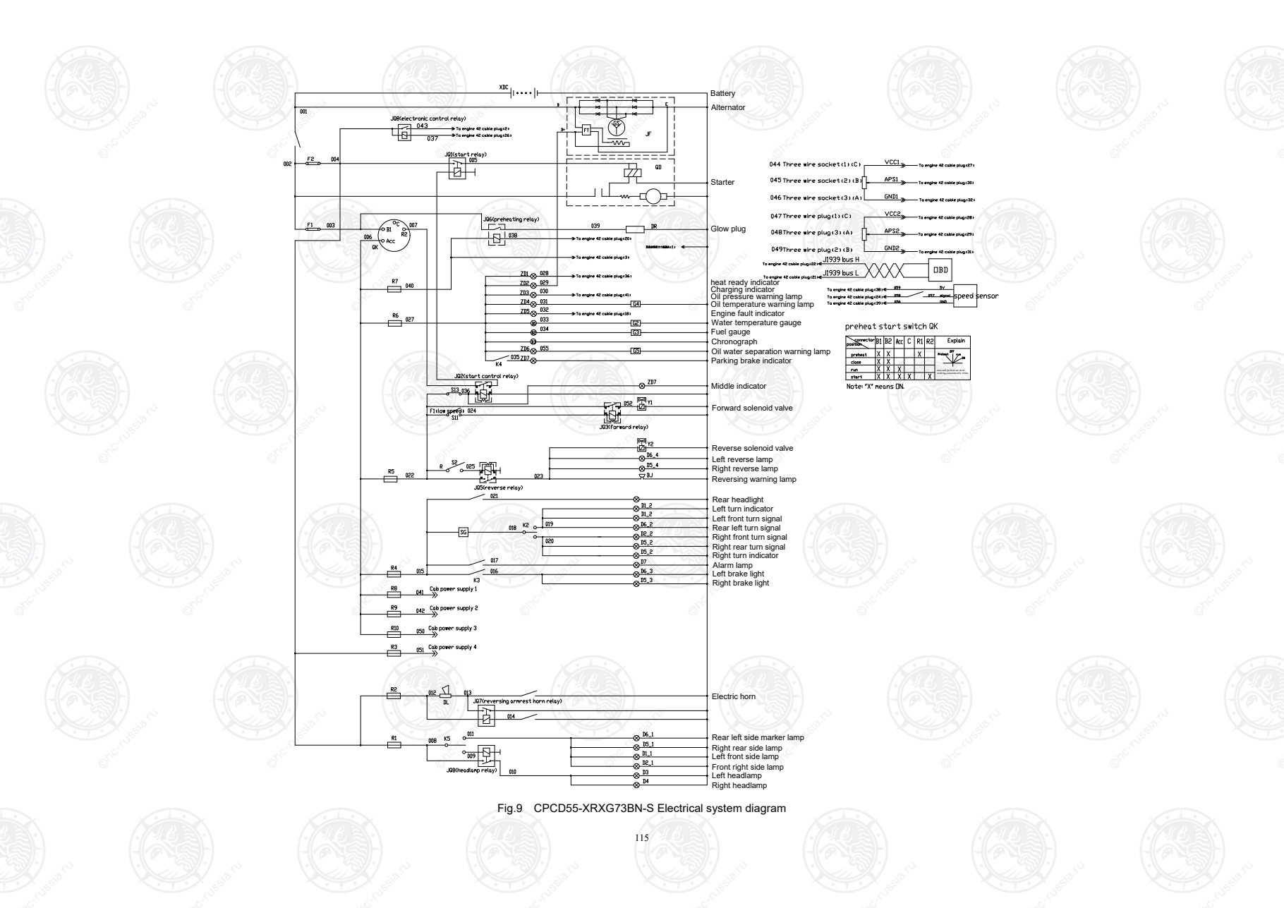
Страница 121
116
start and preheat are short
working,automatically return.
Fig.10 CPCD40/45-XRW19,CPCD50-XRXW19Electrical system diagram(without OPS)
Оригинальная страница: таблицы и схемы
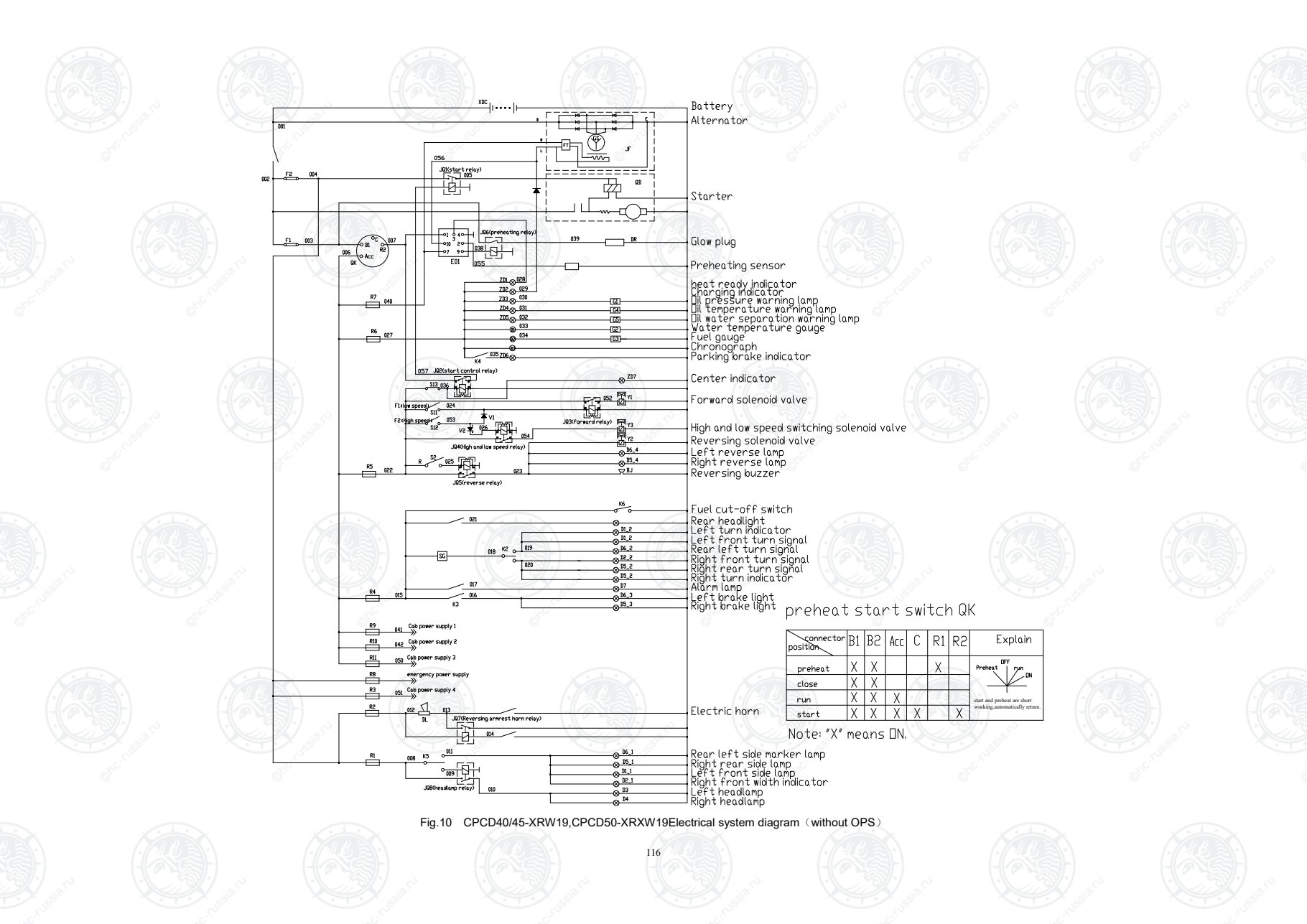
Страница 122
117
Fig.10-1 CPCD40/45-XRW19,CPCD50-XRXW19Electrical system diagram(with OPS)
Оригинальная страница: таблицы и схемы
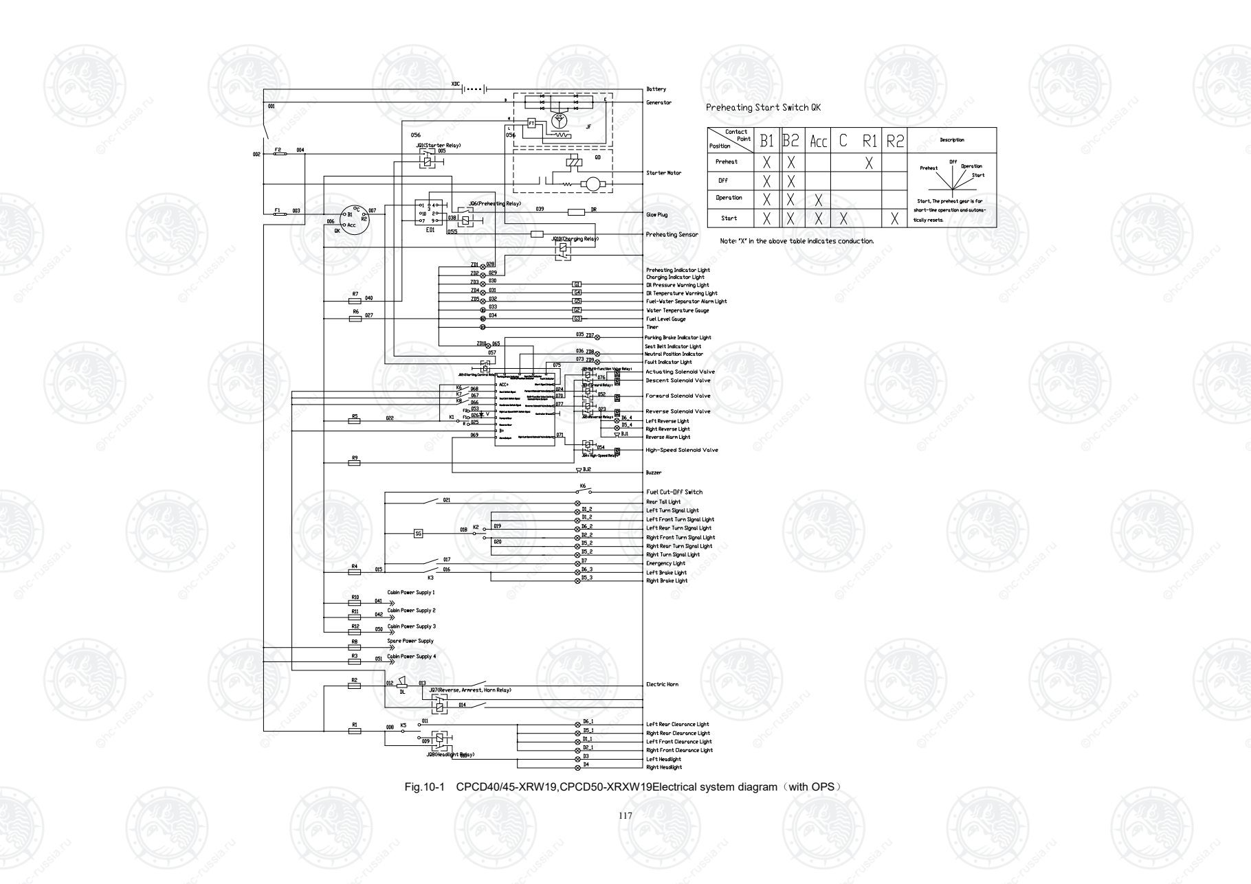
Страница 123
118
NO. Symbol Name QTY Remarks
1 XDC Less maintenance of battery 12V 60Ah 2
2 JF generator -1 Engine matching
3 QD starter -1 Engine matching
4 QK Preheat Starter Switch -1 Combination instrument matching
5 K1 Combination switch (direction switch) 1
6 K2 Combination switch (turn signal switch) 1
7 K3 brake light switch 1
8 K4 Horn button -1 Steering wheel matching
9 K5 Combination switch (light switch)
10 B1 Water temperature gauge 24V -1 Combination instrument matching
11 B2 Oil gauge 24V -1 Combination instrument matching
12 B3 Timer 24V -1 Combination instrument matching
13 ZD1-ZD5 Alarm light 24V 2W -5 Combination instrument matching
14 G1 Oil pressure alarm -1 Engine matching
15 G2 Water Temperature Sensor -1 Combination instrument matching
16 G3 Oil quantity sensor -1 Combination instrument matching
17 G4 Oil temperature alarm 1
18 D1 D2 Front small light 21W 10W 2
19 D3 D4 Front headlight 15W 2
20 D5 D6 Combination rear light 21W21W/5W10W 2
21 DR GLOW PLUG -1 Engine matching
22 E01 Preheating timer 24V -1 Control box matching
23 BJ Reverse alarm 24V 1
24 DL Electric horn 24V 1
25 SG Flasher 24V 1 Control box matching
26 JQ1 Starting relay 24V 1 Control box matching
27 JQ2 Starting control relay 24V 1 Control box matching
28 JQ3 Forward relay 24V 1 Control box matching
29 JQ4 High and low speed relay 24V 1 Control box matching
30 JQ5 Reverse gear relay 24V 1 Control box matching
31 JQ6 Preheating relay 24V 1 Control box matching
32 JQ7 Reverse armrest horn relay 24V 1 Control box matching
33 JQ8 Headlight relay 24V 1 Control box matching
34 JQ9 Cold start auxiliary relay 24V 1 Control box matching
35 R1-R11 fuse 1 Control box matching
Fig.10-2 CPCD40/45-XRW19,CPCD50-XRXW19Electrical system diagram(with OPS)
Оригинальная страница: таблицы и схемы
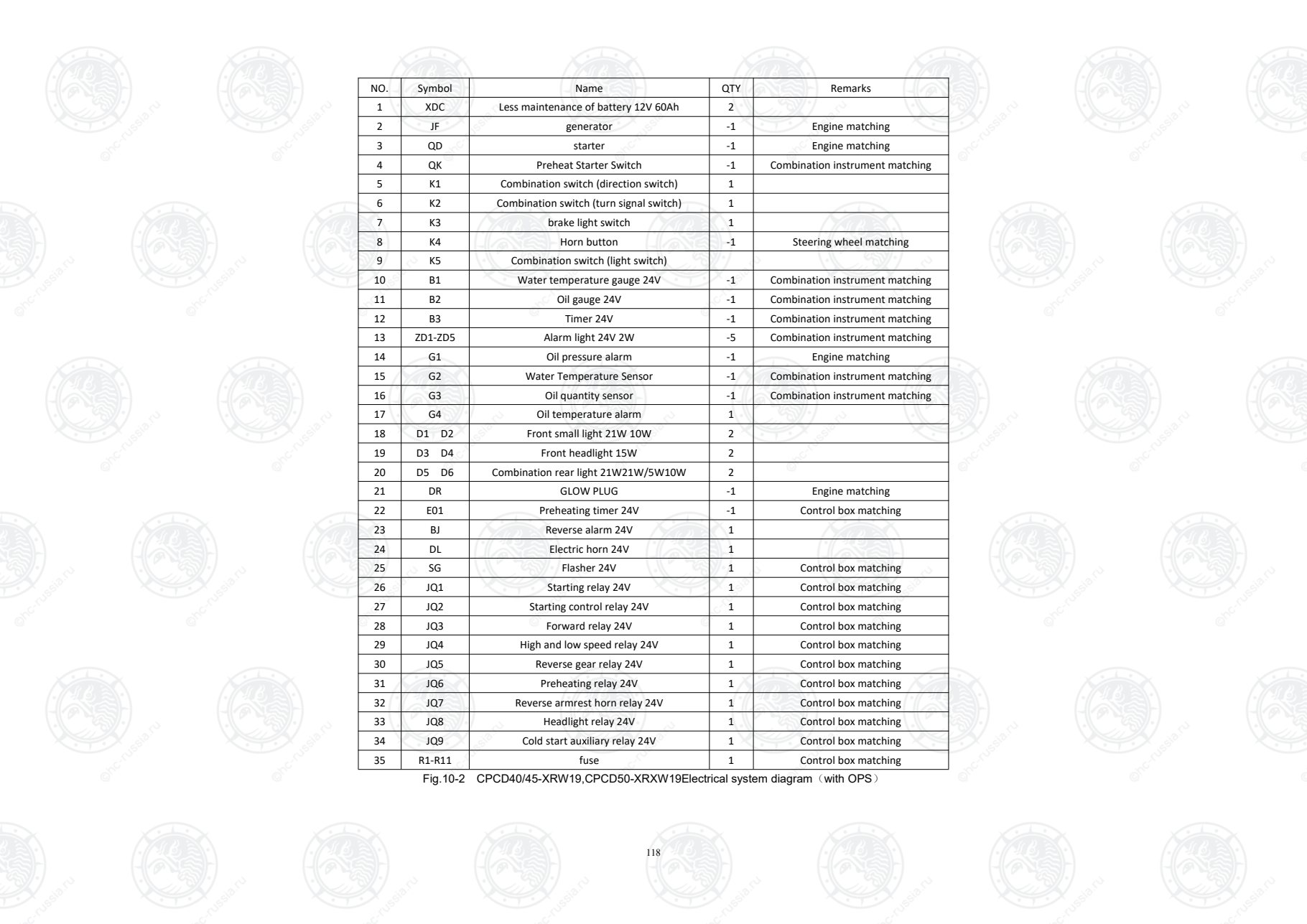
Страница 124
119
start and preheat are short
working,automatically return.
Fig.11 CPCD40/45-XRG82,CPCD50-XRXG82Electrical system diagram
Оригинальная страница: таблицы и схемы
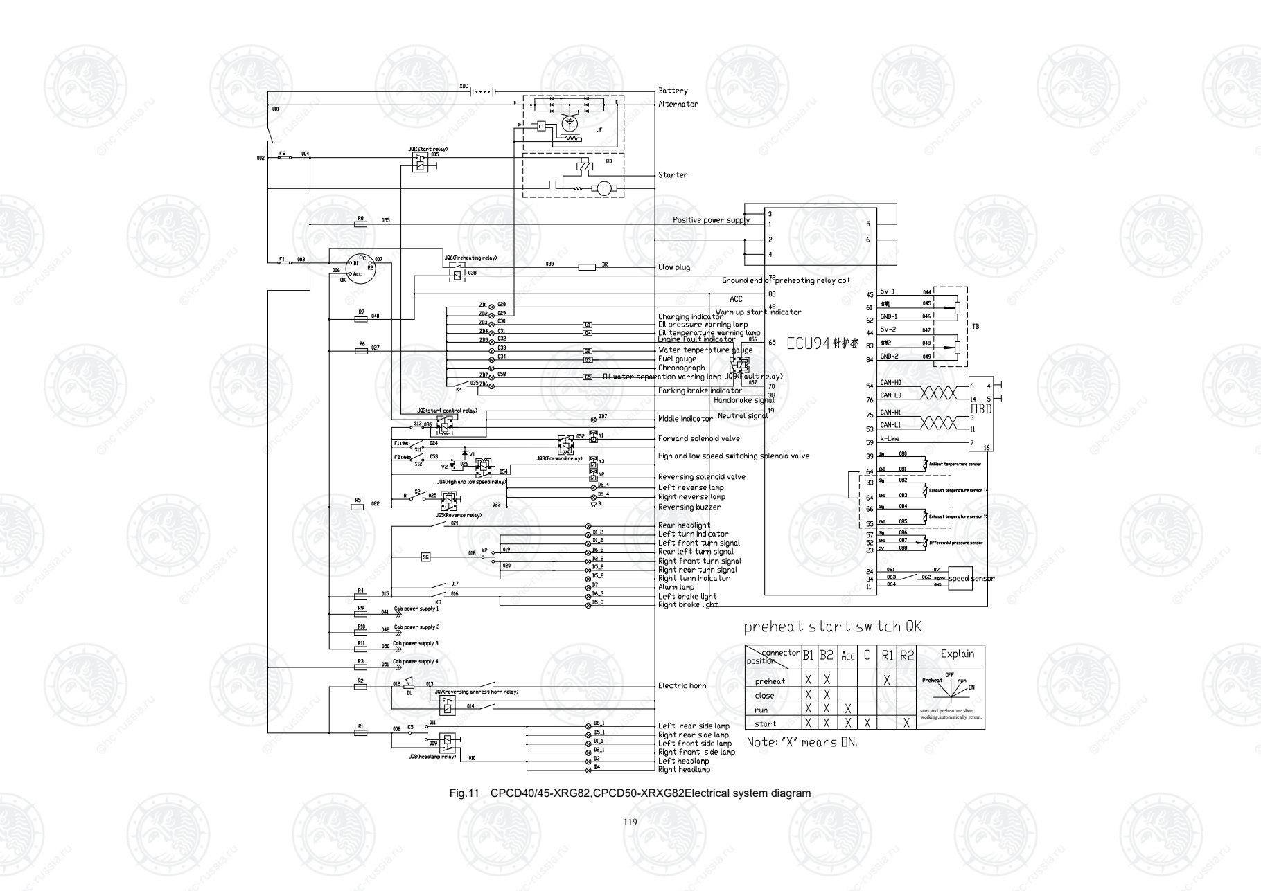
Страница 125
120
Right headlamp
Left headlamp
Front right side lamp
Left front side lamp
Right rear side lamp
Rear left side marker lamp
Electric horn
Reversing warning lamp
Right reverse lamp
Left reverse lamp
Reverse solenoid valve
Right brake light
Left brake light
Alarm lamp
Right turn indicator
Right rear turn signal
Right front turn signal
Rear left turn signal
Left front turn signal
Left turn indicator
Rear headlight
start and preheat are short
working,automatically return.
Middle indicator
Forward solenoid valve
Water temperature gauge
Oil water separation warning lamp
Fuel gauge
Chronograph
Parking brake indicator
Oil temperature warning lamp
Oil pressure warning lamp
Charging indicator
Engine fault indicator
Warm up start indicator
Starter
Alternator
Battery
Glow plug

Positive power supply
Fig.12 CPCD55-XRXG76BN-S Electrical system diagram
Оригинальная страница: таблицы и схемы
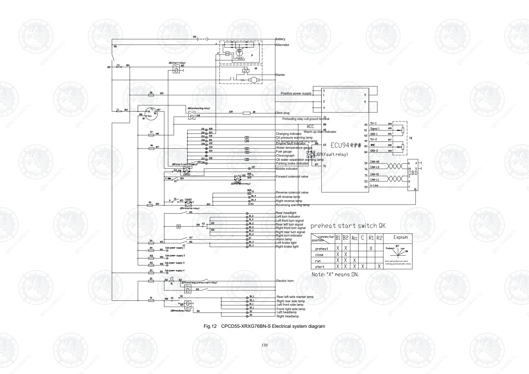
Страница 126
121
Fig.13 CPCD40/45-XRG93, CPCD50-XRXG93
Оригинальная страница: таблицы и схемы
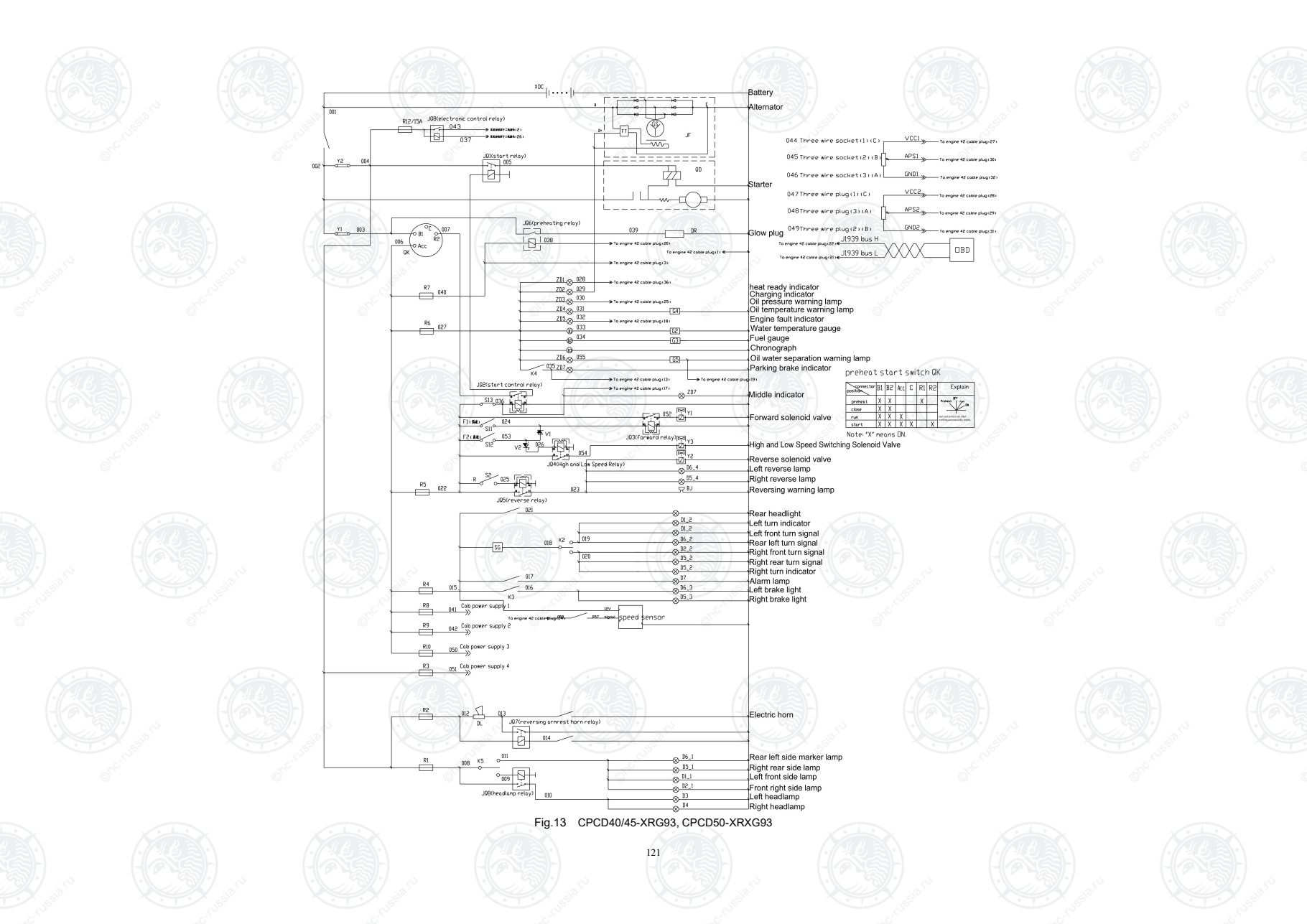
Страница 127
122
Fig.7 CPCD40/45-XRW76, CPCD50-XRXW76 Electrical system diagram(OPS)
Оригинальная страница: таблицы и схемы
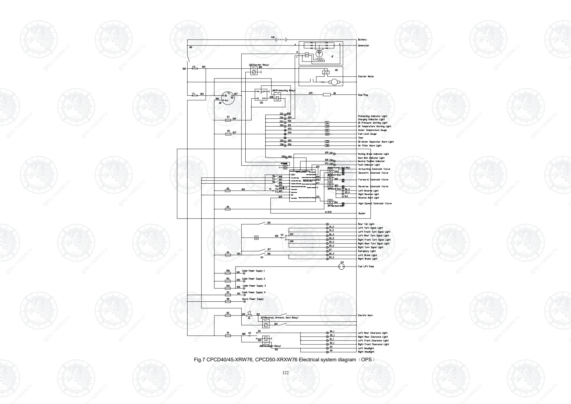
Страница 128
123
Fig.8-1 CPCD40/45-XRW76BN, CPCD50-XRXW76BN Electrical system diagram(OPS)
Оригинальная страница: таблицы и схемы
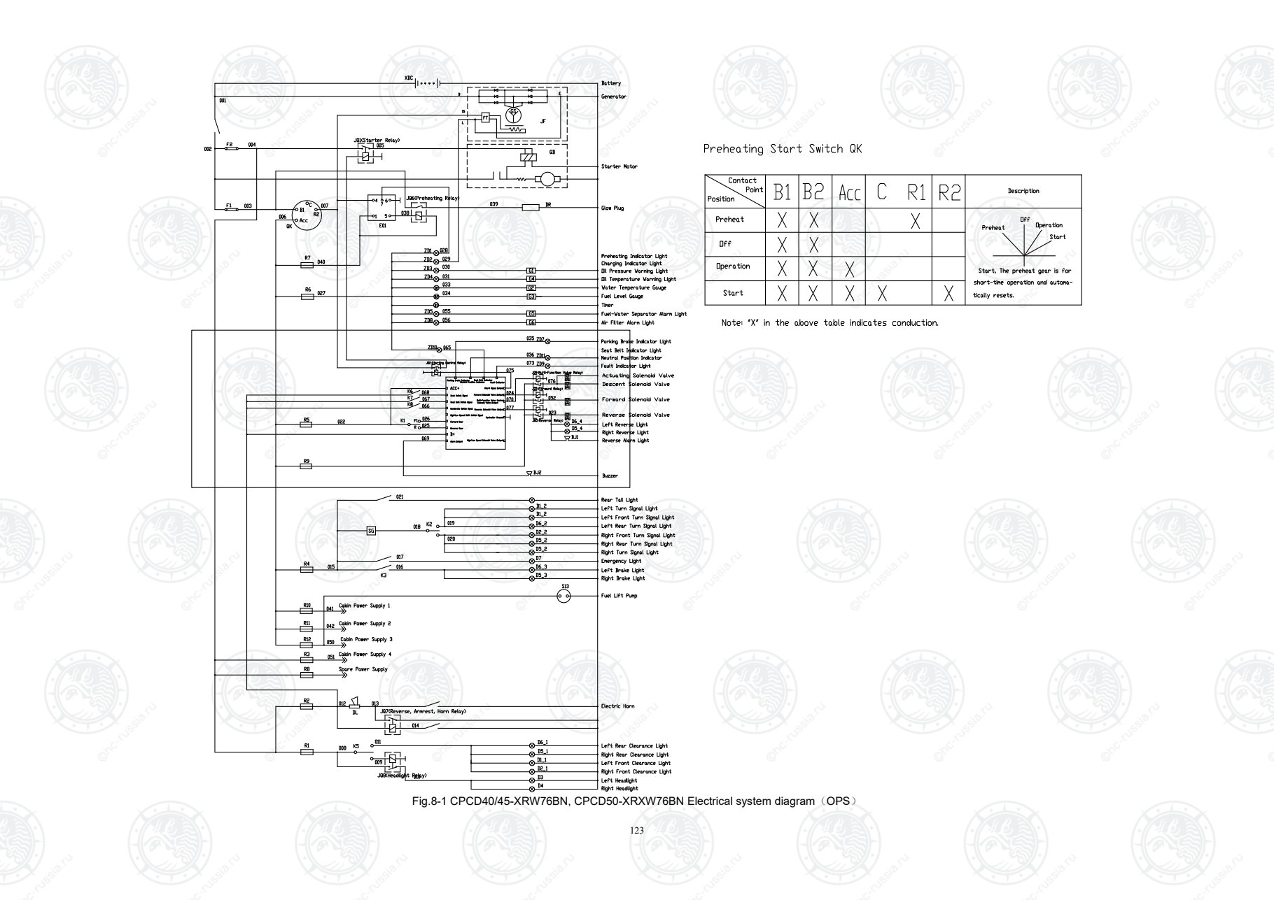
Страница 129
124
NO. Symbol Name QTY Remarks
1 XDC Less maintenance of battery 12V 60Ah 2
2 JF generator 1 Engine matching
3 QD starter 1 Engine matching
4 QK Preheat Starter Switch 1 Combination instrument matching
5 K1 Combination switch (direction switch) 1
6 K2 Combination switch (turn signal switch) 1
7 K3 brake light switch 1
8 K4 Horn button 1 Steering wheel matching
9 K5 Combination switch (light switch) 1
10 B1 water temperature gauge 1 Combination instrument matching
11 B2 fuel gauge 1 Combination instrument matching
12 B3 Chronograph 1 Combination instrument matching
13 ZD1-ZD8 pilot lamp 8 Combination instrument matching
14 G1 Oil pressure alarm 1 Engine matching
15 G2 Water Temperature Sensor 1 Combination instrument matching
16 G3 Oil quantity sensor 1 Combination instrument matching
17 G4 Oil temperature alarm 1
18 D1 D2 Front small light 21W 10W 2
19 D3 D4 Front headlight 15W 2
20 D5 D6 Combination rear light 21W/21W/5W/10W 2
21 DR GLOW PLUG 1 Engine matching
22 E01 Preheating timer 24V 1 Control box matching
23 BJ Reverse alarm 24V 1
24 DL Electric horn 24V 1
25 SG Flasher 24V 1 Control box matching
26 JQ1 Starting relay 24V 1 Control box matching
27 JQ2 Starting control relay 24V 1 Control box matching
28 JQ3 Forward relay 24V 1 Control box matching
29 JQ4 High and low speed relay 24V 1 Control box matching
30 JQ5 Reverse gear relay 24V 1 Control box matching
31 JQ6 Preheating relay 24V 1 Control box matching
32 JQ7 Reverse armrest horn relay 24V 1 Control box matching
33 JQ8 Headlight relay 24V 1 Control box matching
34 R1-R12 fuse 1 Control box matching
Fig.8-2 CPCD40/45-XRW76BN, CPCD50-XRXW76BN Electrical system diagram(OPS)
Оригинальная страница: таблицы и схемы
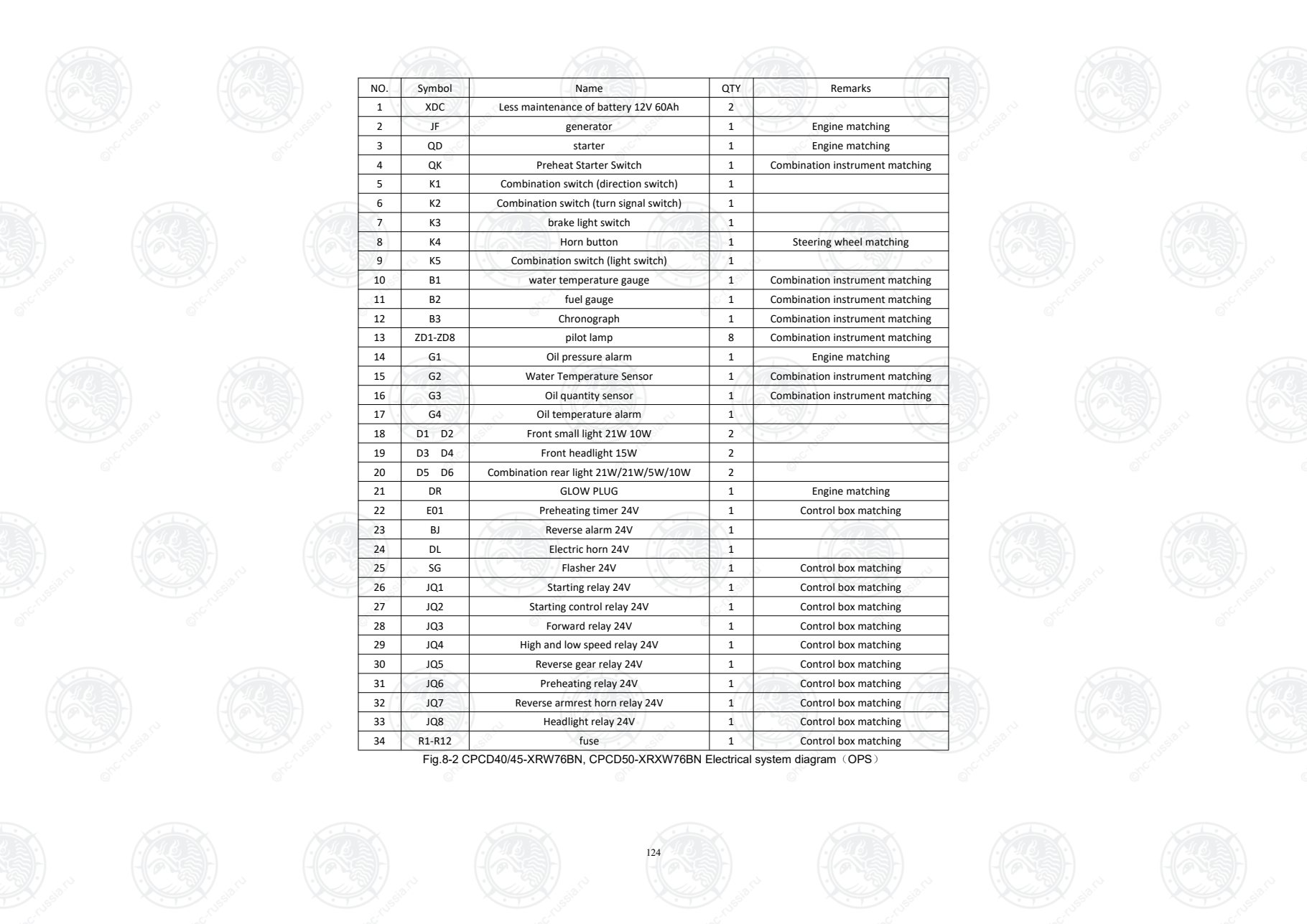
Уточните документ по серийному номеру
Если исполнение машины отличается от указанного в руководстве, передайте фото её заводской таблички в сервис.