

Hangcha X 1,0–5,0 т: Operation & Maintenance 2025
Англоязычный заводской PDF по эксплуатации и техническому обслуживанию погрузчиков X с ДВС, редакция февраля 2025 года.
- Модели и серия
- X Series Internal Combustion Counterbalanced 1.0t–X5.0t; точные модели в таблицах
- Язык документа
- Английский
- Назначение документа
- Эксплуатация и обслуживание · 02/2025
Для какой техники этот документ
В документе описаны X Series Internal Combustion Counterbalanced 1.0t–X5.0t; точные модели в таблицах. Полный индекс на заводской табличке должен соответствовать перечню руководства. Для вашей машины используйте документацию нужной редакции и комплектации. Редакция руководства: 02/2025.
Читать полную инструкциюДокумент целиком
Скачать PDF Полный текст инструкции
Страница 1
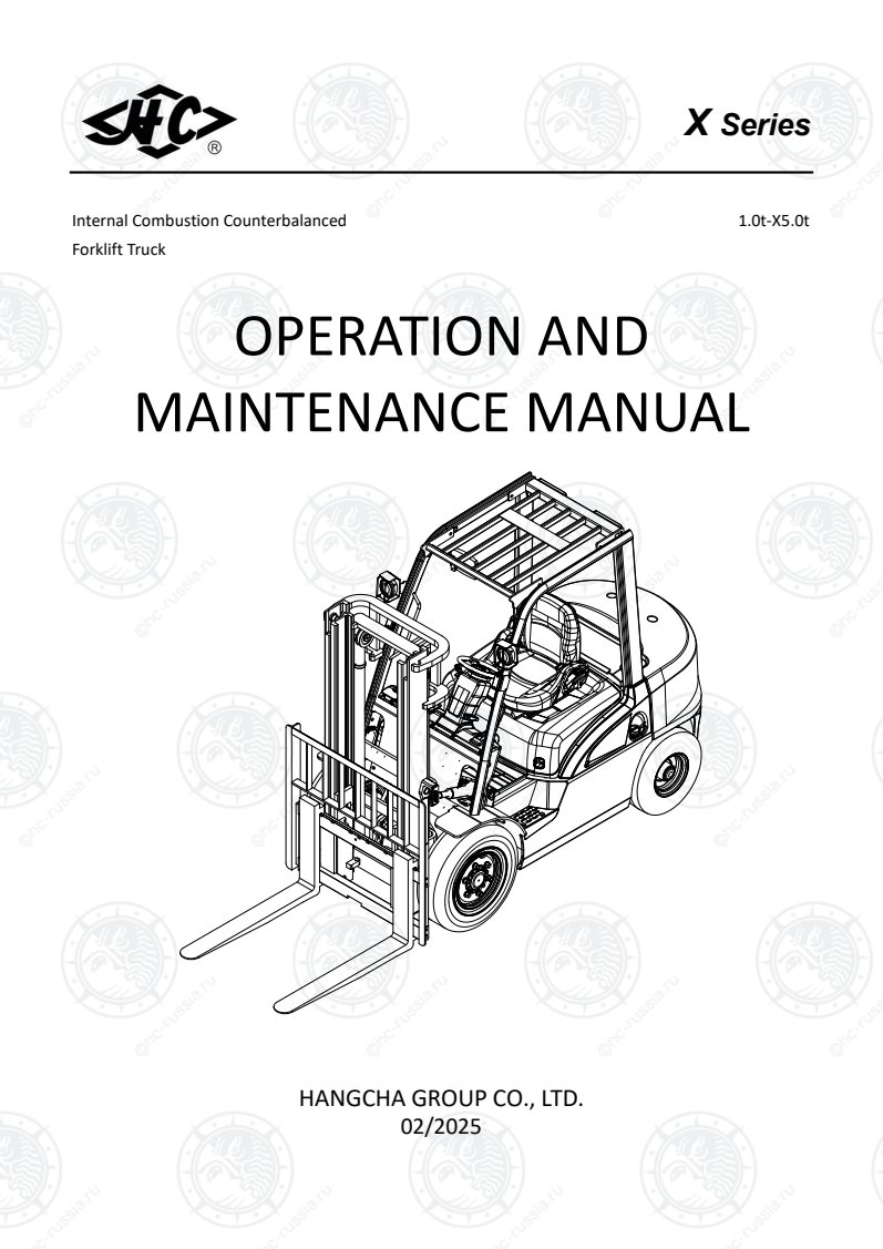
X Series
Internal Combustion Counterbalanced 1.0t-X5.0t
Forklift Truck
OPERATION AND
MAINTENANCE MANUAL
HANGCHA GROUP CO., LTD.
02/2025
Оригинальная страница: таблицы и схемы
Страница 2
Preface
The 1-X5.0t X series internal combustion counterbalanced forklift truck is a new model developed
by our company, and features high energy efficiency and environmental protection, an attractive
shape and superior performance.
G71/G72/G76 forklift trucks are equipped with high-pressure common-rail electronically
controlled engines conforming to China III emission standards, featuring high injection pressure
and high torque at low speed, low emissions and optimized fuel economy.
G98/G92/G93/G82/H5 forklift trucks are equipped with electronically controlled engines
conforming to China IV emission standards, featuring high injection pressure and high torque at low
speed, low emissions and optimized fuel economy.
China IV forklift trucks over 4t are equipped with emission devices, operators should carefully
read the information about them in this manual to avoid the loss of life and property due to
improper operation. China IV forklift trucks over 4t are equipped with truck-mounted terminals,
but the intelligent modules are not optional.
This manual introduces the safety, operation, general structure and maintenance procedures for
this forklift truck. The drivers, maintenance staff and equipment management staff must read and
familiarize themselves with this manual before use.
Some contents in this manual may be different from your forklift truck due to continuous design
updates and product improvements.
The illustrations and pictures used in this manual may not be exactly the same as the detailed
structure of your forklift truck.
This manual is also applicable to container forklift trucks and forklift trucks equipped with
attachments.
For any queries, please contact the sales company or agent of HANGCHA GROUP CO., LTD.
Website for Intelligent modules for this forklift truck:<http://hcfims.com>
©02. 2025, HANGCHA GROUP CO., LTD.
Оригинальная страница: таблицы и схемы
Страница 3
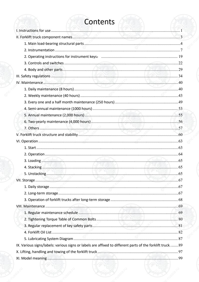
Contents
I. Instructions for use .................................................................................................................................. 1
II. Forklift truck component names ............................................................................................................ 3
1. Main load-bearing structural parts .................................................................................................4
2. Instrumentation .............................................................................................................................. 7
2. Operating instructions for instrument keys: ............................................................................. 19
3. Controls and switches ...................................................................................................................22
4. Body and other parts .................................................................................................................... 29
III. Safety regulations ................................................................................................................................ 34
IV. Maintenance ........................................................................................................................................40
1. Daily maintenance (8 hours) .........................................................................................................40
2. Weekly maintenance (40 hours) ...................................................................................................43
3. Every one and a half month maintenance (250 hours) ................................................................49
4. Semi-annual maintenance (1000 hours) ...................................................................................... 53
5. Annual maintenance (2,000 hours) .............................................................................................. 55
6. Two-yearly maintenance (4,000 hours) ........................................................................................56
7. Others ............................................................................................................................................57
V. Forklift truck structure and stability .....................................................................................................60
VI. Operation .............................................................................................................................................63
1. Start ...............................................................................................................................................63
2. Operation ...................................................................................................................................... 64
3. Loading ..........................................................................................................................................65
4. Stacking ......................................................................................................................................... 65
5. Unstacking .....................................................................................................................................65
VII. Storage ................................................................................................................................................67
1. Daily storage ..................................................................................................................................67
2. Long-term storage .........................................................................................................................67
3. Operation of forklift trucks after long-term storage .................................................................... 68
VIII. Maintenance ......................................................................................................................................69
1. Regular maintenance schedule .................................................................................................... 69
2. Tightening Torque Table of Common Bolts .................................................................................. 80
3. Regular replacement of key safety parts ......................................................................................81
4. Forklift Oil List ............................................................................................................................... 82
5. Lubricating System Diagram ......................................................................................................... 87
IX. Various signs/labels: various signs or labels are affixed to different parts of the forklift truck. ....... 89
X. Lifting, handling and towing of the forklift truck ................................................................................. 97
XI. Model meaning ....................................................................................................................................99
Оригинальная страница: таблицы и схемы
Страница 4
XII. Main technical performance parameters ........................................................................................ 107
XIII. Precautions for using the LPG forklift truck .................................................................................... 170
XIV. Usage and maintenance methods for the lead-acid battery ..........................................................185
XV. Use, installation and safety rules for attachments ..........................................................................189
XVI. OPS (Operator Presence Sensing) system instruction ....................................................................192
XVII. Forklift daily check and maintenance sheet .................................................................................. 194
Оригинальная страница: таблицы и схемы
Страница 5
1
I. Instructions for use
In order to ensure personal and equipment safety, the driver should take the following precautions:
1. Only drivers with proper training and a valid license should operate the vehicle.
2. Check each control and alarm device before driving, and any damage or defects should be repaired
before operation.
3. The load should not exceed the specified value when handling; the forks should be fully inserted
into the load so that it is uniformly positioned on the fork; do not use a single fork to lift cargo.
4. Start, turn, drive, brake and stop smoothly; slow down on wet or slippery roads when steering.
5. Loads should be placed as low as possible and the mast should tilt backward when driving.
6. Be careful when driving on ramps; move forward when driving up gradients greater than one in ten
and move backwards when driving down ramps; do not turn when driving up or down ramps; do
not carry out loading and unloading operations when the forklift is in motion.
7. Pay attention to pedestrians, barriers, and bumpy surfaces when driving and be aware of the upper
clearance of the forklift truck.
8. Do not stand on the forks and do not carry passengers.
9. Do not stand under the forks or walk under the forks.
10. Do not operate the truck and its attachments from anywhere except the driver’s seat.
11. Do not handle unsecured or loosely stacked cargo and be careful when handling large cargo.
12. Protect cargo on high lifting forklift trucks with a lift height of more than 3m from falling down and
take preventive measures if necessary.
13. Try to tilt the mast backward when the high lifting forklift truck is in operation and tilt forward
within the minimum range during loading and unloading operations.
14. When driving on wharfs or temporary decking, you should be extra careful and drive slowly.
15. The driver should not stay in the truck and should shut down the engine when refueling; keep
sources of ignition away when checking the battery or fuel tank level.
16. When a forklift truck with attachments is idling, it should be operated in the same manner as a
loaded forklift truck;
17. Drop the forks to the ground, switch the gear lever to the neutral position, engage the parking
brake device properly, shut down the engine, and disconnect the power when leaving the truck.
Engage the parking brake device properly when parking on ramps; place cushion blocks under the
wheels when parking for a long time.
18. In the event of a sudden fault when lifting cargo or driving on gradients, causing leakage of storage
battery electrolyte, hydraulic oil and brake fluid, or a flat tire etc., personnel should be organized
for repair immediately, the truck should be kept in a safe condition, and professional maintenance
personnel or the seller should be contacted.
19. Noise and vibration will be generated during installation and assembly processes; please choose
proper tools and assembly methods to reduce the impact of noise pollution on the environment.
20. The work surface where the forklift truck is used should be a solid and flat cement pavement,
Оригинальная страница: таблицы и схемы
Страница 6
2
asphalt pavement or concrete pavement. When there is snow, ice, water or other foreign matter
on the road, the truck can only be used after it has been fully cleared away; otherwise, the truck is
likely to lose control, resulting in an accident.
21. In the event of breakdown, the truck should be first moved to a place where it does not obstruct
traffic. If the breakdown is caused by the brake system or steering system, the truck should be
carried away with a proper carrier loader (see the vehicle handling content); if it is caused by other
reasons, the truck should be towed with an appropriate vehicle; rope should be fixed outside the
truck body when towing. Obey traffic rules when towing a forklift truck on the highway.
22. Do not operate the forklift truck or carry cargo after disassembling the internal combustion engine
hood, water tank cover plate, overhead guard, mast backrest or other protective devices.
23. There should be sufficient lighting in the truck working area. Turn on the head lights when working
at night, there should be sufficient lighting in the work area.
24.Do..not...conduct.......side....shift.....operations..........with....a.forklift........truck.....equipped........with....automatic.........adjustable..........
distance........forks.....when....it..is..loaded......to..prevent.......the...forklift........truck.....from....losing......balance.......and...damaging........
components............
25. Please do not tilt the mast forward or backward or lift the mast to the extreme position during
idling where possible before the hydraulic oil temperature reaches normal operating level.
26. Do not revise or modify the forklift truck without the written approval of the forklift truck
manufacturer; otherwise, it may affect the rated load and stability or safe operation. This includes:
Assembly and disassembly of brakes and steering, changes to the field of vision and attachments.
When the forklift truck manufacturer agrees to revise or modify the truck, they should also agree to
update and revise the bearing nameplate, label, and operation and maintenance manual.
27. If the forklift manufacturer is no longer in operation and no other enterprise has taken over the
business, the user needs to seek a capable industrial forklift manufacturer for technical support
with its refitted documents. In which case, the user must follow these rules:
(1) Submit the modified and refitted scheme to the engineers from a industrial forklift manufacture
for further design, test and application, and the safety of the refitted forklift trucks should be
guaranteed.
(2) Keep a permanent record of the modifications made to the forklift design, test and application.
(3) Update and properly revise the bearing nameplate, label, and operation and maintenance
manual.
(4) Attach a permanent and visible label to the forklift truck (the label should contain this
information: refit method, date, responsible company and address).
Оригинальная страница: таблицы и схемы
Страница 7
3
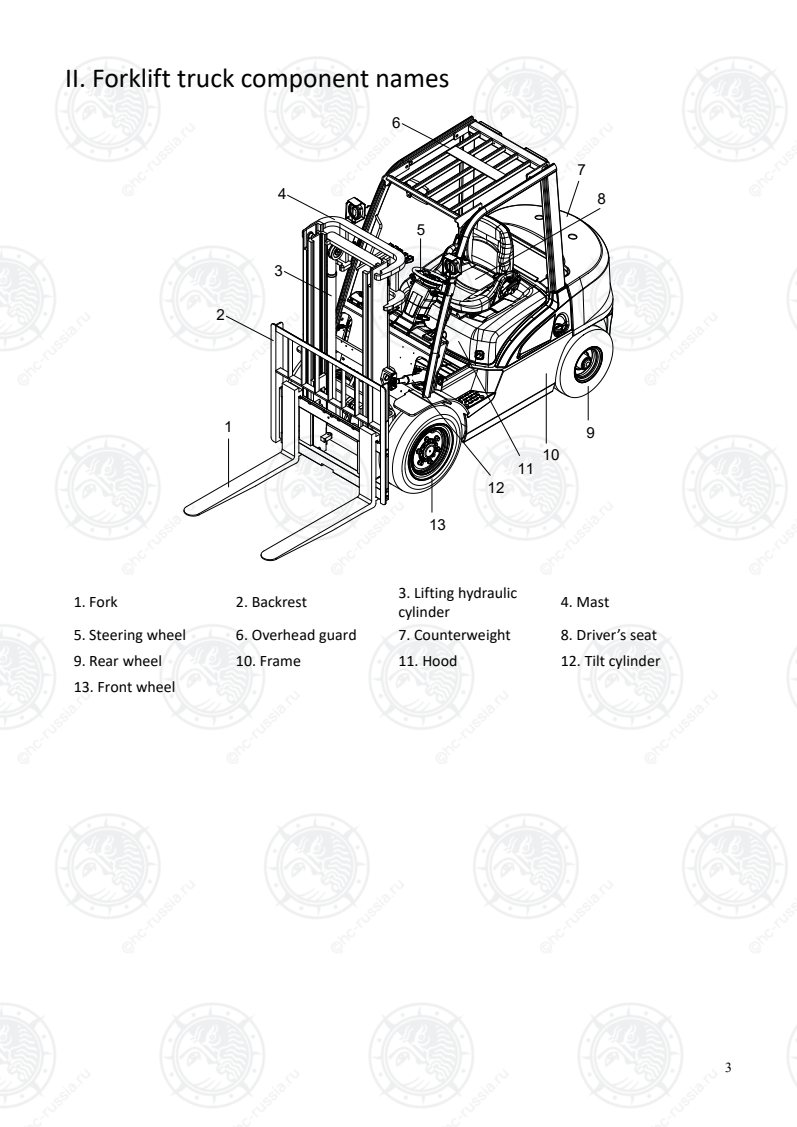
II. Forklift truck component names
3
5
6
8
11
7
9
10
13
1
2
12
4
1. Fork 2. Backrest 3. Lifting hydraulic
cylinder 4. Mast
5. Steering wheel 6. Overhead guard 7. Counterweight 8. Driver’s seat
9. Rear wheel 10. Frame 11. Hood 12. Tilt cylinder
13. Front wheel
Оригинальная страница: таблицы и схемы
Страница 8
4
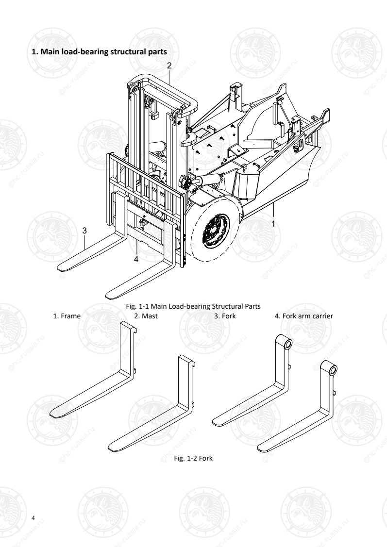
1. Main load-bearing structural parts
1
2
3
4
Fig. 1-1 Main Load-bearing Structural Parts
1. Frame 2. Mast 3. Fork 4. Fork arm carrier
Fig. 1-2 Fork
Оригинальная страница: таблицы и схемы
Страница 9
5
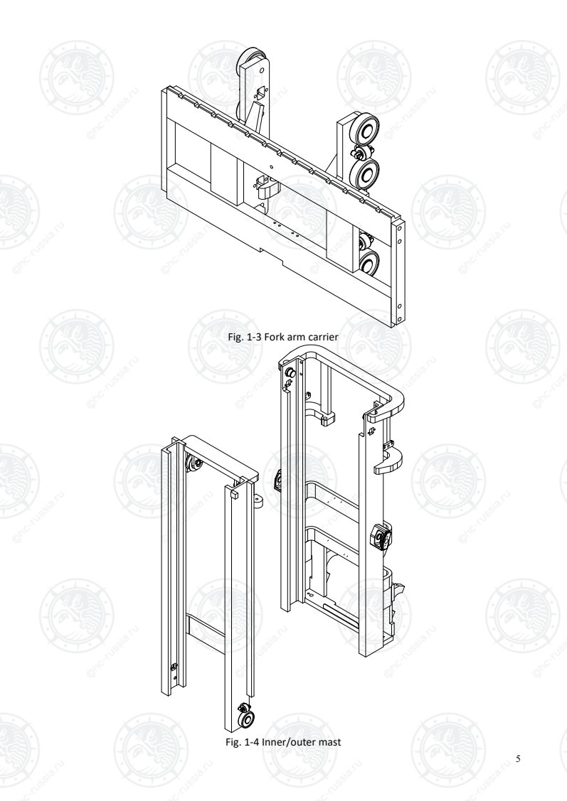
Fig. 1-3 Fork arm carrier
Fig. 1-4 Inner/outer mast
Оригинальная страница: таблицы и схемы
Страница 10
6
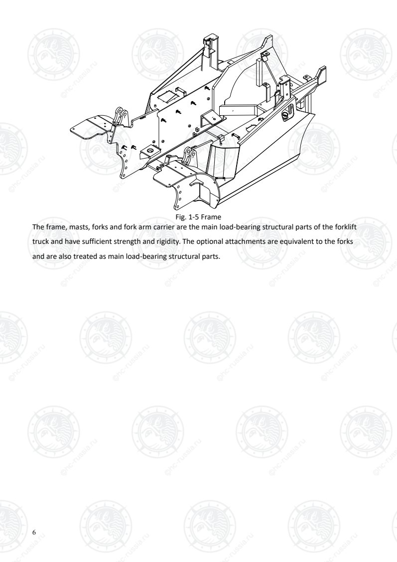
Fig. 1-5 Frame
The frame, masts, forks and fork arm carrier are the main load-bearing structural parts of the forklift
truck and have sufficient strength and rigidity. The optional attachments are equivalent to the forks
and are also treated as main load-bearing structural parts.
Оригинальная страница: таблицы и схемы
Страница 11
7
2. Instrumentation
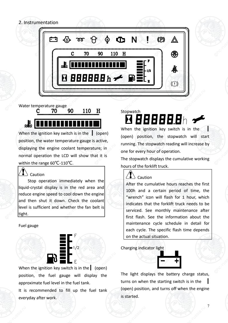
Water temperature gauge
When the ignition key switch is in the ┃ (open)
position, the water temperature gauge is active,
displaying the engine coolant temperature; in
normal operation the LCD will show that it is
within the range 60℃-110℃.
Caution
Stop operation immediately when the
liquid-crystal display is in the red area and
reduce engine speed to cool down the engine
and then shut it down. Check the coolant
level is sufficient and whether the fan belt is
tight.
Fuel gauge
When the ignition key switch is in the┃ (open)
position, the fuel gauge will display the
approximate fuel level in the fuel tank.
It is recommended to fill up the fuel tank
everyday after work.
Stopwatch
When the ignition key switch is in the ┃
(open) position, the stopwatch will start
running. The stopwatch reading will increase by
one for every hour of operation.
The stopwatch displays the cumulative working
hours of the forklift truck.
Caution
After the cumulative hours reaches the first
100h and a certain period of time, the
“wrench” icon will flash for 1 hour, which
indicates that the forklift truck needs to be
serviced. See monthly maintenance after
first flash. See the information about the
maintenance cycle schedule in detail for
each cycle. The specific flash time depends
on the actual situation.
Charging indicator light
The light displays the battery charge status,
turns on when the starting switch is in the ┃
(open) position, and turns off when the engine
is started.
Оригинальная страница: таблицы и схемы
Страница 12
8
Caution
If the light continues to turn on or flash
during operation, it indicates that the
charging is abnormal and immediate
inspection is required.
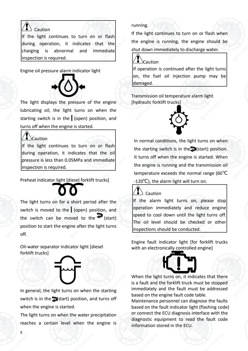
Engine oil pressure alarm indicator light
The light displays the pressure of the engine
lubricating oil, the light turns on when the
starting switch is in the ┃ (open) position, and
turns off when the engine is started.
Caution
If the light continues to turn on or flash
during operation, it indicates that the oil
pressure is less than 0.05MPa and immediate
inspection is required.
Preheat indicator light [diesel forklift trucks]
The light turns on for a short period after the
switch is moved to the ┃ (open) position, and
the switch can be moved to the (start)
position to start the engine after the light turns
off.
Oil-water separator indicator light [diesel
forklift trucks]
In general, the light turns on when the starting
switch is in the (start) position, and turns off
when the engine is started.
The light turns on when the water precipitation
reaches a certain level when the engine is
running.
If the light continues to turn on or flash when
the engine is running, the engine should be
shut down immediately to discharge water.
Caution
If operation is continued after the light turns
on, the fuel oil injection pump may be
damaged.
Transmission oil temperature alarm light
[hydraulic forklift trucks]
In normal conditions, the light turns on when
the starting switch is in the (start) position.
It turns off when the engine is started. When
the engine is running and the transmission oil
temperature exceeds the normal range (60℃
-120℃), the alarm light will turn on.
Caution
If the alarm light turns on, please stop
operation immediately and reduce engine
speed to cool down until the light turns off.
The oil level should be checked or other
inspections should be conducted.
Engine fault indicator light [for forklift trucks
with an electronically controlled engine]
When the light turns on, it indicates that there
is a fault and the forklift truck must be stopped
immediately and the fault must be addressed
based on the engine fault code table.
Maintenance personnel can diagnose the faults
based on the fault indicator light (flashing code)
or connect the ECU diagnosis interface with the
diagnostic equipment to read the fault code
information stored in the ECU.
Оригинальная страница: таблицы и схемы
Страница 13
9
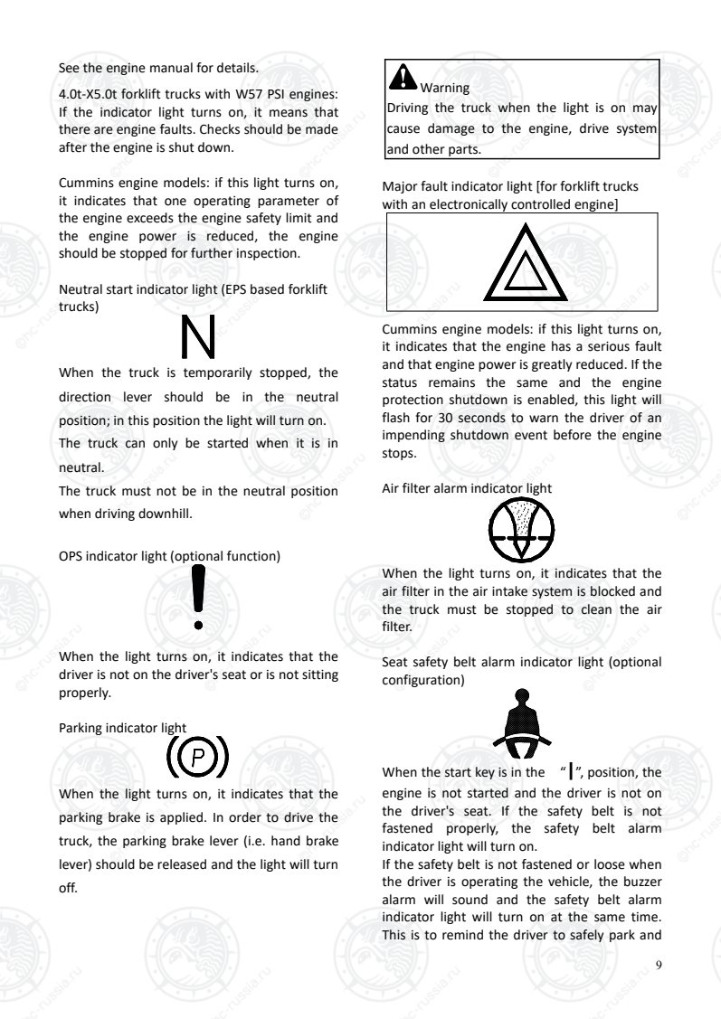
See the engine manual for details.
4.0t-X5.0t forklift trucks with W57 PSI engines:
If the indicator light turns on, it means that
there are engine faults. Checks should be made
after the engine is shut down.
Cummins engine models: if this light turns on,
it indicates that one operating parameter of
the engine exceeds the engine safety limit and
the engine power is reduced, the engine
should be stopped for further inspection.
Neutral start indicator light (EPS based forklift
trucks)
When the truck is temporarily stopped, the
direction lever should be in the neutral
position; in this position the light will turn on.
The truck can only be started when it is in
neutral.
The truck must not be in the neutral position
when driving downhill.
OPS indicator light (optional function)
When the light turns on, it indicates that the
driver is not on the driver's seat or is not sitting
properly.
Parking indicator light
When the light turns on, it indicates that the
parking brake is applied. In order to drive the
truck, the parking brake lever (i.e. hand brake
lever) should be released and the light will turn
off.
Warning
Driving the truck when the light is on may
cause damage to the engine, drive system
and other parts.
Major fault indicator light [for forklift trucks
with an electronically controlled engine]
Cummins engine models: if this light turns on,
it indicates that the engine has a serious fault
and that engine power is greatly reduced. If the
status remains the same and the engine
protection shutdown is enabled, this light will
flash for 30 seconds to warn the driver of an
impending shutdown event before the engine
stops.
Air filter alarm indicator light
When the light turns on, it indicates that the
air filter in the air intake system is blocked and
the truck must be stopped to clean the air
filter.
Seat safety belt alarm indicator light (optional
configuration)
When the start key is in the “┃”, position, the
engine is not started and the driver is not on
the driver's seat. If the safety belt is not
fastened properly, the safety belt alarm
indicator light will turn on.
If the safety belt is not fastened or loose when
the driver is operating the vehicle, the buzzer
alarm will sound and the safety belt alarm
indicator light will turn on at the same time.
This is to remind the driver to safely park and
Оригинальная страница: таблицы и схемы
Страница 14
10
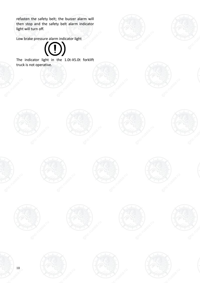
refasten the safety belt; the buzzer alarm will
then stop and the safety belt alarm indicator
light will turn off.
Low brake pressure alarm indicator light
The indicator light in the 1.0t-X5.0t forklift
truck is not operative.
Оригинальная страница: таблицы и схемы
Страница 15
11
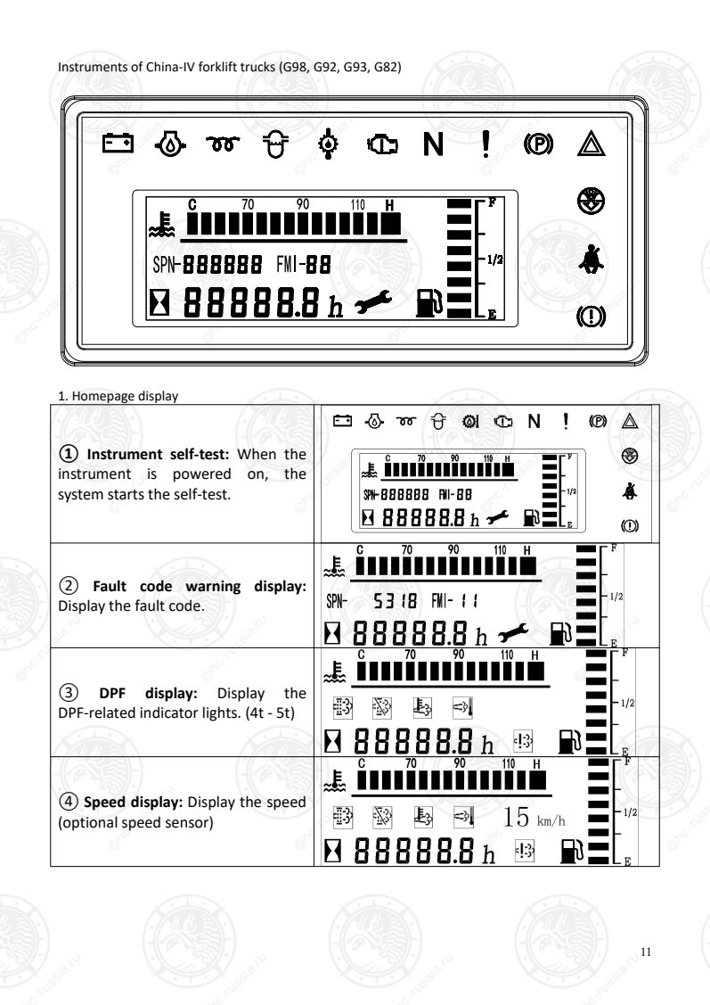
Instruments of China-IV forklift trucks (G98, G92, G93, G82)
C H
1. Homepage display
① Instrument self-test: When the
instrument is powered on, the
system starts the self-test.
② Fault code warning display:
Display the fault code.
③ DPF display: Display the
DPF-related indicator lights. (4t - 5t)
④ Speed display: Display the speed
(optional speed sensor)
Оригинальная страница: таблицы и схемы
Страница 16
12
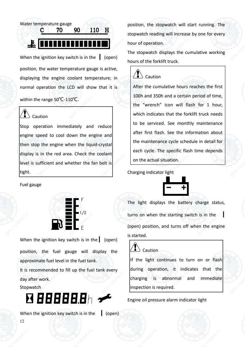
Water temperature gauge
When the ignition key switch is in the ┃ (open)
position, the water temperature gauge is active,
displaying the engine coolant temperature; in
normal operation the LCD will show that it is
within the range 50℃-110℃.
Caution
Stop operation immediately and reduce
engine speed to cool down the engine and
then stop the engine when the liquid-crystal
display is in the red area. Check the coolant
level is sufficient and whether the fan belt is
tight.
Fuel gauge
When the ignition key switch is in the┃ (open)
position, the fuel gauge will display the
approximate fuel level in the fuel tank.
It is recommended to fill up the fuel tank every
day after work.
Stopwatch
When the ignition key switch is in the ┃ (open)
position, the stopwatch will start running. The
stopwatch reading will increase by one for every
hour of operation.
The stopwatch displays the cumulative working
hours of the forklift truck.
Caution
After the cumulative hours reaches the first
100h and 350h and a certain period of time,
the “wrench” icon will flash for 1 hour,
which indicates that the forklift truck needs
to be serviced. See monthly maintenance
after first flash. See the information about
the maintenance cycle schedule in detail for
each cycle. The specific flash time depends
on the actual situation.
Charging indicator light
The light displays the battery charge status,
turns on when the starting switch is in the ┃
(open) position, and turns off when the engine
is started.
Caution
If the light continues to turn on or flash
during operation, it indicates that the
charging is abnormal and immediate
inspection is required.
Engine oil pressure alarm indicator light
Оригинальная страница: таблицы и схемы
Страница 17
13
The light displays the pressure of the engine
lubricating oil, the light turns on when the
starting switch is in the ┃ (open) position, and
turns off when the engine is started.
Caution
If the light continues to turn on or flash
during operation, it indicates that the oil
pressure is less than 0.05MPa and immediate
inspection is required.
Preheat indicator light [diesel forklift trucks]
The light turns on for a short period after the
switch is moved to the┃(open) position, and the
switch can be moved to the (start) position to
start the engine after the light turns off.
Oil-water separator indicator light [diesel forklift
trucks]
In general, the light turns on when the starting
switch is in the (start) position, and turns off
when the engine is started.
The light turns on when the water precipitation
reaches a certain level when the engine is
running.
If the light continues to turn on or flash when
the engine is running, the engine should be shut
down immediately to discharge water.
Caution
If operation is continued after the light turns
on, the fuel oil injection pump may be
damaged.
Transmission oil temperature alarm light
[hydraulic forklift trucks]
In normal conditions, the light turns on when
the starting switch is in the (start) position. It
turns off when the engine is started. When the
engine is running and the transmission oil
temperature exceeds the normal range (60 ℃
-120℃), the alarm light will turn on.
Caution
If the alarm light turns on, please stop
operation immediately and reduce engine
speed to cool down until the light turns off.
The oil level should be checked or other
inspections should be conducted.
Engine fault indicator light [for forklift trucks
with an electronically controlled engine]
Оригинальная страница: таблицы и схемы
Страница 18
14
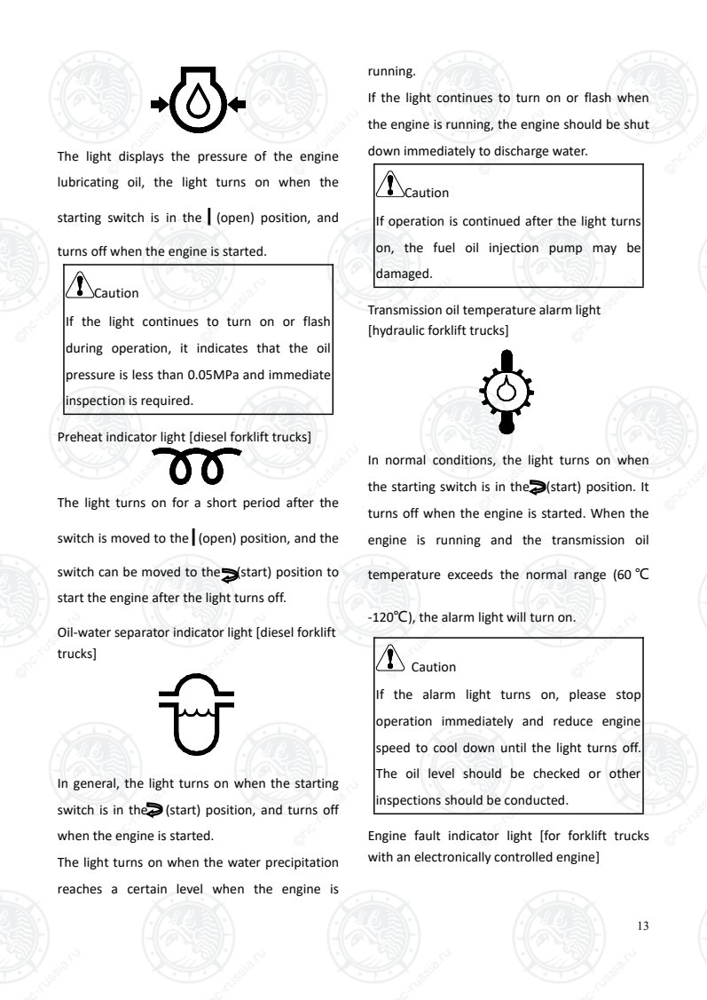
When the light turns on, it indicates that there is
a fault and the forklift truck must be stopped
immediately and the fault must be addressed
based on the engine fault code table.
Maintenance personnel can diagnose the faults
based on the fault code displayed on the fault
code indicator light or connect the ECU
diagnosis interface with the diagnostic
equipment to read the fault code information
stored in the ECU.
See the engine manual for details.
Neutral start indicator light
When the truck is temporarily stopped, the
direction lever should be in the neutral position;
in this position the light will turn on.
The truck can only be started when it is in
neutral.
The truck must not be in the neutral position
when driving downhill.
Vehicle-mounted terminal fault indicator light
(standard configuration for domestic vehicles),
OPS indicator light (optional function for export
vehicles)
Vehicle-mounted terminal fault indicator light:
the light “!” turns on when there are any faults
in the vehicle-mounted terminal communication
antenna, positioning antenna and CAN bus, the
signal is not normal, or the vehicle is in a
dismantled state. When the light is on, it is
necessary to check the vehicle-mounted
terminal and notify the service provider.
OPS indicator light: When the light turns on, it
indicates that the driver is not on the driver's
seat or is not sitting properly.
Parking indicator light
When the light turns on, it indicates that the
parking brake is applied. In order to drive the
truck, the parking brake lever (i.e. hand brake
lever) should be released and the light will turn
off.
Warning
Driving the truck when the light is on may
cause damage to the engine, drive system
and other parts.
Major fault indicator light [for forklift trucks with
an electronically controlled engine]
Air filter alarm indicator light
Оригинальная страница: таблицы и схемы
Страница 19
15
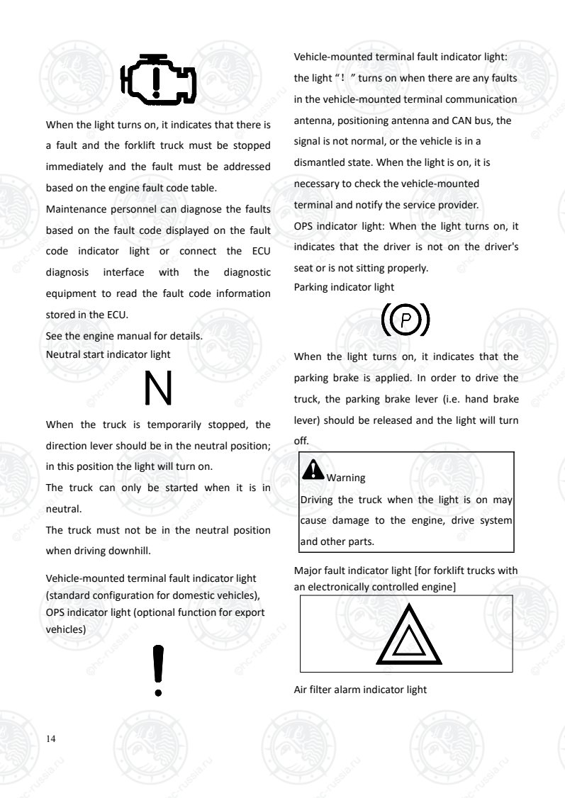
When the light turns on, it indicates that the air
filter in the air intake system is blocked and the
truck must be stopped to clean the air filter.
Seat safety belt alarm indicator light (optional
configuration)
When the start key is in the “┃”, position, the
engine is not started and the driver is not on the
driver's seat. If the safety belt is not fastened
properly, the safety belt alarm indicator light will
turn on.
If the safety belt is not fastened or loose when
the driver is operating the vehicle, the buzzer
alarm will sound and the safety belt alarm
indicator light will turn on at the same time. This
is to remind the driver to safely park and
refasten the safety belt; the buzzer alarm will
then stop and the safety belt alarm indicator
light will turn off.
Low brake pressure alarm indicator light
The indicator light in the 1.5t -5.0t forklift truck
is not operative.
Fault indicator light
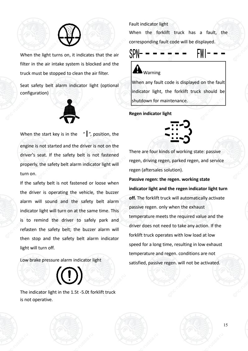
When the forklift truck has a fault, the
corresponding fault code will be displayed.
Warning
When any fault code is displayed on the fault
indicator light, the forklift truck should be
shutdown for maintenance.
Regen indicator light
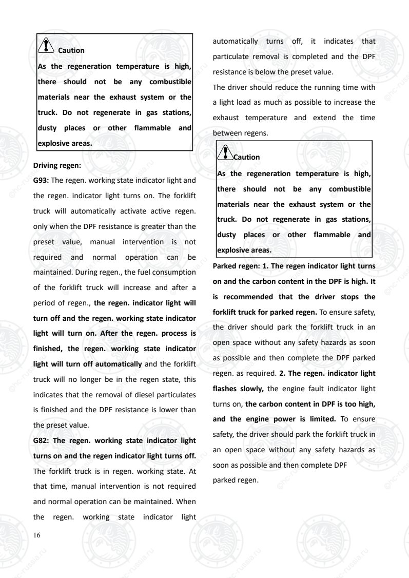
There are four kinds of working state: passive
regen, driving regen, parked regen, and service
regen (aftersales solution).
Passive regen: the regen. working state
indicator light and the regen indicator light turn
off. The forklift truck will automatically activate
passive regen. only when the exhaust
temperature meets the required value and the
driver does not need to take any action. If the
forklift truck operates with low load at low
speed for a long time, resulting in low exhaust
temperature and regen. conditions are not
satisfied, passive regen. will not be activated.
Оригинальная страница: таблицы и схемы
Страница 20
16
Caution
As the regeneration temperature is high,
there should not be any combustible
materials near the exhaust system or the
truck. Do not regenerate in gas stations,
dusty places or other flammable and
explosive areas.
Driving regen:
G93: The regen. working state indicator light and
the regen. indicator light turns on. The forklift
truck will automatically activate active regen.
only when the DPF resistance is greater than the
preset value, manual intervention is not
required and normal operation can be
maintained. During regen., the fuel consumption
of the forklift truck will increase and after a
period of regen., the regen. indicator light will
turn off and the regen. working state indicator
light will turn on. After the regen. process is
finished, the regen. working state indicator
light will turn off automatically and the forklift
truck will no longer be in the regen state, this
indicates that the removal of diesel particulates
is finished and the DPF resistance is lower than
the preset value.
G82: The regen. working state indicator light
turns on and the regen indicator light turns off.
The forklift truck is in regen. working state. At
that time, manual intervention is not required
and normal operation can be maintained. When
the regen. working state indicator light
automatically turns off, it indicates that
particulate removal is completed and the DPF
resistance is below the preset value.
The driver should reduce the running time with
a light load as much as possible to increase the
exhaust temperature and extend the time
between regens.
Caution
As the regeneration temperature is high,
there should not be any combustible
materials near the exhaust system or the
truck. Do not regenerate in gas stations,
dusty places or other flammable and
explosive areas.
Parked regen: 1. The regen indicator light turns
on and the carbon content in the DPF is high. It
is recommended that the driver stops the
forklift truck for parked regen. To ensure safety,
the driver should park the forklift truck in an
open space without any safety hazards as soon
as possible and then complete the DPF parked
regen. as required. 2. The regen. indicator light
flashes slowly, the engine fault indicator light
turns on, the carbon content in DPF is too high,
and the engine power is limited. To ensure
safety, the driver should park the forklift truck in
an open space without any safety hazards as
soon as possible and then complete DPF
parked regen.
Оригинальная страница: таблицы и схемы
Страница 21
17
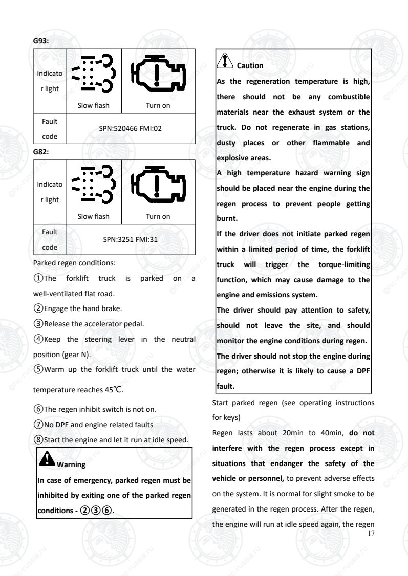
G93:
Indicato
r light
Slow flash Turn on
Fault
code
SPN:520466 FMI:02
G82:
Indicato
r light
Slow flash Turn on
Fault
code
SPN:3251 FMI:31
Parked regen conditions:
①The forklift truck is parked on a
well-ventilated flat road.
②Engage the hand brake.
③Release the accelerator pedal.
④Keep the steering lever in the neutral
position (gear N).
⑤Warm up the forklift truck until the water
temperature reaches 45℃.
⑥The regen inhibit switch is not on.
⑦No DPF and engine related faults
⑧Start the engine and let it run at idle speed.
Warning
In case of emergency, parked regen must be
inhibited by exiting one of the parked regen
conditions - ②③⑥.
Caution
As the regeneration temperature is high,
there should not be any combustible
materials near the exhaust system or the
truck. Do not regenerate in gas stations,
dusty places or other flammable and
explosive areas.
A high temperature hazard warning sign
should be placed near the engine during the
regen process to prevent people getting
burnt.
If the driver does not initiate parked regen
within a limited period of time, the forklift
truck will trigger the torque-limiting
function, which may cause damage to the
engine and emissions system.
The driver should pay attention to safety,
should not leave the site, and should
monitor the engine conditions during regen.
The driver should not stop the engine during
regen; otherwise it is likely to cause a DPF
fault.
Start parked regen (see operating instructions
for keys)
Regen lasts about 20min to 40min, do not
interfere with the regen process except in
situations that endanger the safety of the
vehicle or personnel, to prevent adverse effects
on the system. It is normal for slight smoke to be
generated in the regen process. After the regen,
the engine will run at idle speed again, the regen
Оригинальная страница: таблицы и схемы
Страница 22
18
indicator light will automatically turn off, regen
is finished and the driver can operate the forklift
truck normally.
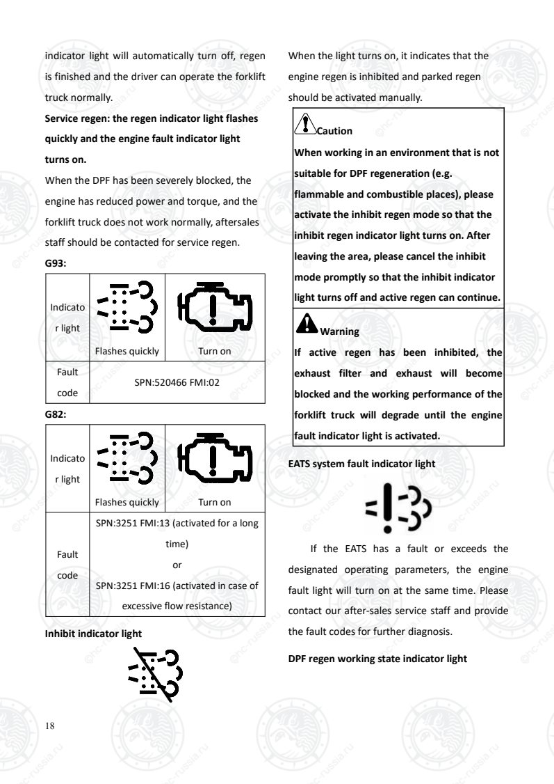
Service regen: the regen indicator light flashes
quickly and the engine fault indicator light
turns on.
When the DPF has been severely blocked, the
engine has reduced power and torque, and the
forklift truck does not work normally, aftersales
staff should be contacted for service regen.
G93:
Indicato
r light
Flashes quickly Turn on
Fault
code
SPN:520466 FMI:02
G82:
Indicato
r light
Flashes quickly Turn on
Fault
code
SPN:3251 FMI:13 (activated for a long
time)
or
SPN:3251 FMI:16 (activated in case of
excessive flow resistance)
Inhibit indicator light
When the light turns on, it indicates that the
engine regen is inhibited and parked regen
should be activated manually.
Caution
When working in an environment that is not
suitable for DPF regeneration (e.g.
flammable and combustible places), please
activate the inhibit regen mode so that the
inhibit regen indicator light turns on. After
leaving the area, please cancel the inhibit
mode promptly so that the inhibit indicator
light turns off and active regen can continue.
Warning
If active regen has been inhibited, the
exhaust filter and exhaust will become
blocked and the working performance of the
forklift truck will degrade until the engine
fault indicator light is activated.
EATS system fault indicator light
If the EATS has a fault or exceeds the
designated operating parameters, the engine
fault light will turn on at the same time. Please
contact our after-sales service staff and provide
the fault codes for further diagnosis.
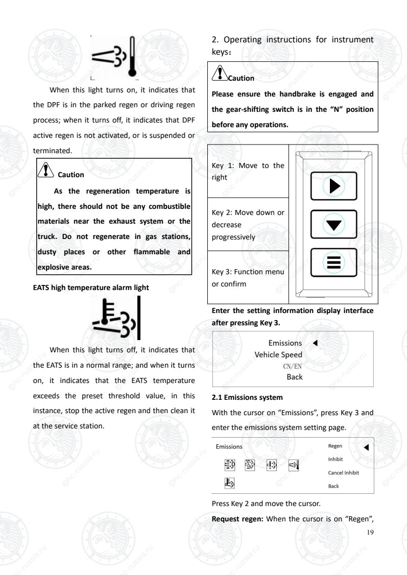
DPF regen working state indicator light
Оригинальная страница: таблицы и схемы
Страница 23
19
When this light turns on, it indicates that
the DPF is in the parked regen or driving regen
process; when it turns off, it indicates that DPF
active regen is not activated, or is suspended or
terminated.
Caution
As the regeneration temperature is
high, there should not be any combustible
materials near the exhaust system or the
truck. Do not regenerate in gas stations,
dusty places or other flammable and
explosive areas.
EATS high temperature alarm light
When this light turns off, it indicates that
the EATS is in a normal range; and when it turns
on, it indicates that the EATS temperature
exceeds the preset threshold value, in this
instance, stop the active regen and then clean it
at the service station.
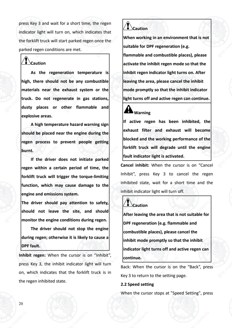
2. Operating instructions for instrument
keys:
Caution
Please ensure the handbrake is engaged and
the gear-shifting switch is in the “N” position
before any operations.
Key 1: Move to the
right
Key 2: Move down or
decrease
progressively
Key 3: Function menu
or confirm
Enter the setting information display interface
after pressing Key 3.
2.1 Emissions system
With the cursor on “Emissions”, press Key 3 and
enter the emissions system setting page.
Press Key 2 and move the cursor.
Request regen: When the cursor is on “Regen”,
Оригинальная страница: таблицы и схемы
Страница 24
20
press Key 3 and wait for a short time, the regen
indicator light will turn on, which indicates that
the forklift truck will start parked regen once the
parked regen conditions are met.
Caution
As the regeneration temperature is
high, there should not be any combustible
materials near the exhaust system or the
truck. Do not regenerate in gas stations,
dusty places or other flammable and
explosive areas.
A high temperature hazard warning sign
should be placed near the engine during the
regen process to prevent people getting
burnt.
If the driver does not initiate parked
regen within a certain period of time, the
forklift truck will trigger the torque-limiting
function, which may cause damage to the
engine and emissions system.
The driver should pay attention to safety,
should not leave the site, and should
monitor the engine conditions during regen.
The driver should not stop the engine
during regen; otherwise it is likely to cause a
DPF fault.
Inhibit regen: When the cursor is on “Inhibit”,
press Key 3, the inhibit indicator light will turn
on, which indicates that the forklift truck is in
the regen inhibited state.
Caution
When working in an environment that is not
suitable for DPF regeneration (e.g.
flammable and combustible places), please
activate the inhibit regen mode so that the
inhibit regen indicator light turns on. After
leaving the area, please cancel the inhibit
mode promptly so that the inhibit indicator
light turns off and active regen can continue.
Warning
If active regen has been inhibited, the
exhaust filter and exhaust will become
blocked and the working performance of the
forklift truck will degrade until the engine
fault indicator light is activated.
Cancel inhibit: When the cursor is on “Cancel
Inhibit”, press Key 3 to cancel the regen
inhibited state, wait for a short time and the
inhibit indicator light will turn off.
Caution
After leaving the area that is not suitable for
DPF regeneration (e.g. flammable and
combustible places), please cancel the
inhibit mode promptly so that the inhibit
indicator light turns off and active regen can
continue.
Back: When the cursor is on the “Back”, press
Key 3 to return to the setting page.
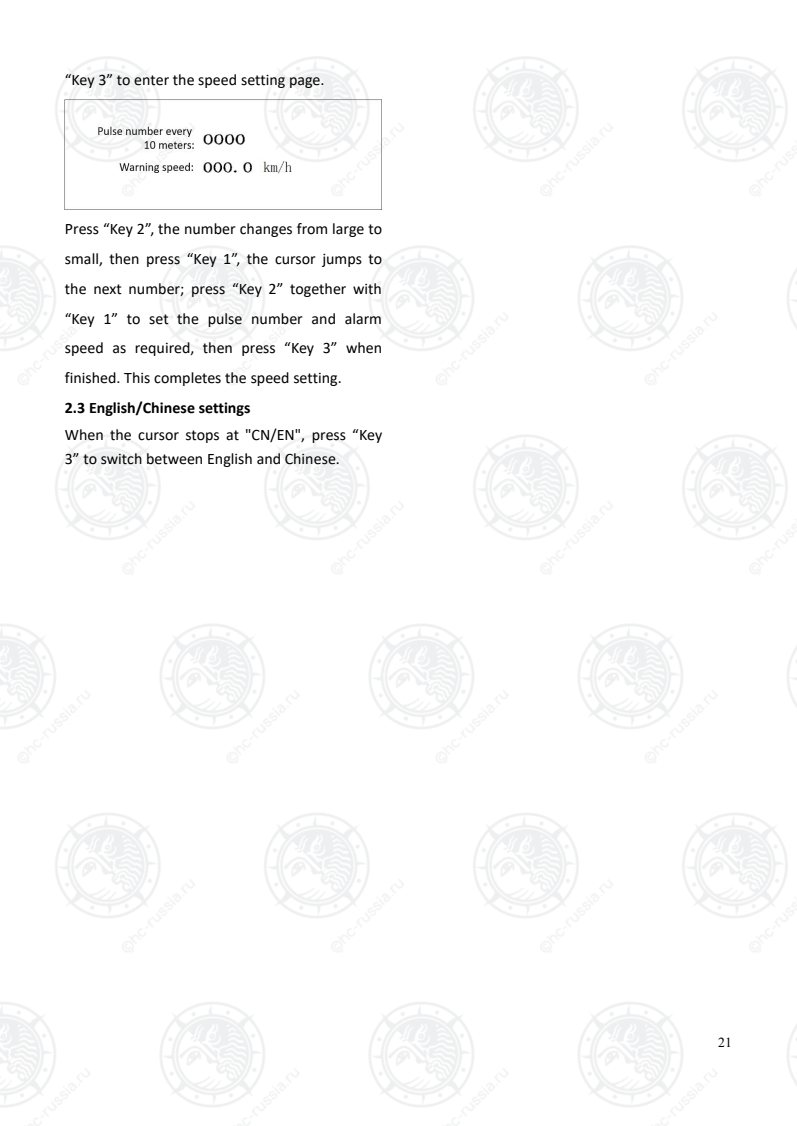
2.2 Speed setting
When the cursor stops at "Speed Setting", press
Оригинальная страница: таблицы и схемы
Страница 25
21
“Key 3” to enter the speed setting page.
Press “Key 2”, the number changes from large to
small, then press “Key 1”, the cursor jumps to
the next number; press “Key 2” together with
“Key 1” to set the pulse number and alarm
speed as required, then press “Key 3” when
finished. This completes the speed setting.
2.3 English/Chinese settings
When the cursor stops at "CN/EN", press “Key
3” to switch between English and Chinese.
Оригинальная страница: таблицы и схемы
Страница 26
22
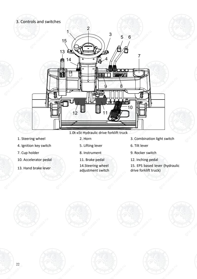
3. Controls and switches
15
1 2
3 65
4 7
89
12 11
10
14
13
1.0t-x5t Hydraulic drive forklift truck
1. Steering wheel 2. Horn 3. Combination light switch
4. Ignition key switch 5. Lifting lever 6. Tilt lever
7. Cup holder 8. Instrument 9. Rocker switch
10. Accelerator pedal 11. Brake pedal 12. Inching pedal
13. Hand brake lever 14.Steering wheel
adjustment switch
15. EPS based lever (hydraulic
drive forklift truck)
Оригинальная страница: таблицы и схемы
Страница 27
23
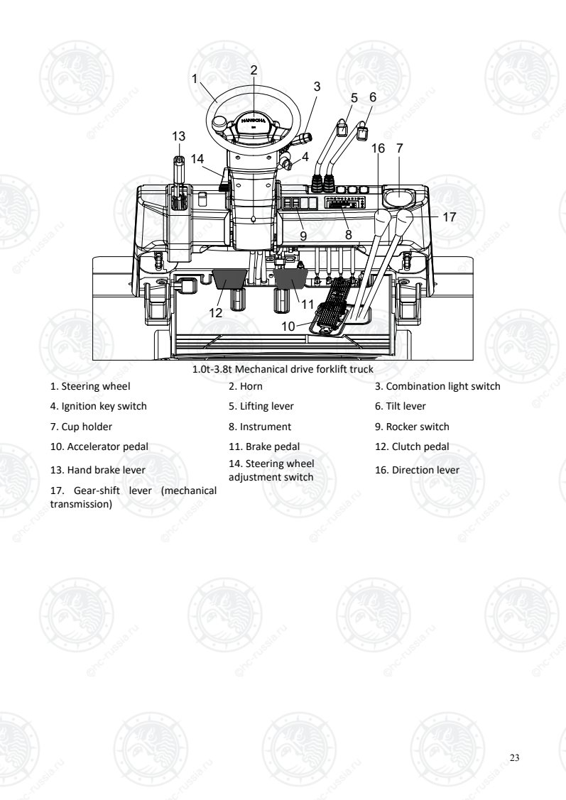
17
16
1 2
3
65
4 7
89
12 11
10
14
13
1.0t-3.8t Mechanical drive forklift truck
1. Steering wheel 2. Horn 3. Combination light switch
4. Ignition key switch 5. Lifting lever 6. Tilt lever
7. Cup holder 8. Instrument 9. Rocker switch
10. Accelerator pedal 11. Brake pedal 12. Clutch pedal
13. Hand brake lever 14. Steering wheel
adjustment switch 16. Direction lever
17. Gear-shift lever (mechanical
transmission)
Оригинальная страница: таблицы и схемы
Страница 28
24
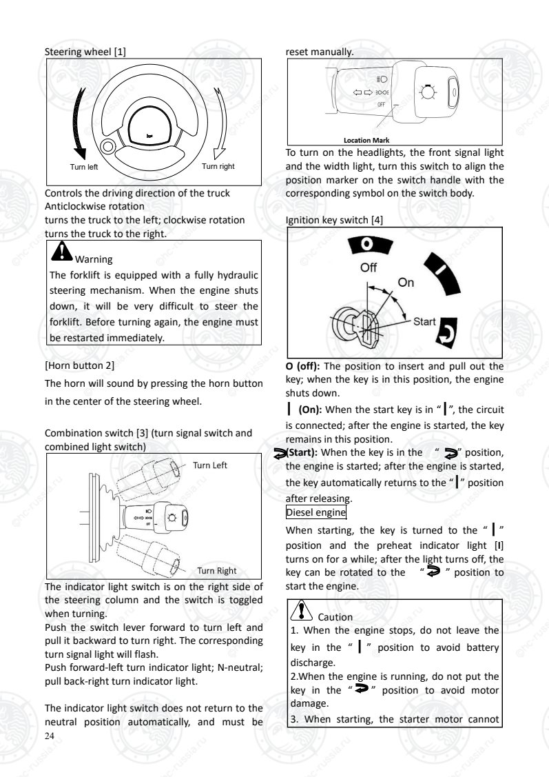
Steering wheel [1]
Turn left Turn right
Controls the driving direction of the truck
Anticlockwise rotation
turns the truck to the left; clockwise rotation
turns the truck to the right.
Warning
The forklift is equipped with a fully hydraulic
steering mechanism. When the engine shuts
down, it will be very difficult to steer the
forklift. Before turning again, the engine must
be restarted immediately.
[Horn button 2]
The horn will sound by pressing the horn button
in the center of the steering wheel.
Combination switch [3] (turn signal switch and
combined light switch)
The indicator light switch is on the right side of
the steering column and the switch is toggled
when turning.
Push the switch lever forward to turn left and
pull it backward to turn right. The corresponding
turn signal light will flash.
Push forward-left turn indicator light; N-neutral;
pull back-right turn indicator light.
The indicator light switch does not return to the
neutral position automatically, and must be
reset manually.
To turn on the headlights, the front signal light
and the width light, turn this switch to align the
position marker on the switch handle with the
corresponding symbol on the switch body.
Ignition key switch [4]
O (off): The position to insert and pull out the
key; when the key is in this position, the engine
shuts down.
┃ (On): When the start key is in “┃”, the circuit
is connected; after the engine is started, the key
remains in this position.
(Start): When the key is in the “ ” position,
the engine is started; after the engine is started,
the key automatically returns to the “┃” position
after releasing.
Diesel engine
When starting, the key is turned to the “ ┃ ”
position and the preheat indicator light [I]
turns on for a while; after the light turns off, the
key can be rotated to the “ ” position to
start the engine.
Caution
1. When the engine stops, do not leave the
key in the “ ┃ ” position to avoid battery
discharge.
2.When the engine is running, do not put the
key in the “ ” position to avoid motor
damage.
3. When starting, the starter motor cannot
Оригинальная страница: таблицы и схемы
Страница 29
25
continuously rotate for more than 5s and the
interval between consecutive starts should be
120s.
Lifting lever [5]
This lever is used to lift or lower the forks.
Push forward - Down; Pull back - Up
The lifting speed is controlled by the backward
tilt angle of the lever and the accelerator pedal.
The lowering speed is only controlled by the
forward tilt angle of the lever.
Tilt lever [6]
This lever is used to tilt the mast forward and
backward.
Push forward - Forward tilt; Pull back -
Backward tilt
The tilt speed is determined by the tilt angle of
the lever and the throttle control.
Caution
The multi-way valve is equipped with a
forward tilt self-locking valve. Therefore
when the engine shuts down, the mast
cannot tilt forward even if the tilt lever is
pushed forward.
Sideshift control lever
This lever is used to move the side shift
frame to the left or right.
Push forward – Move left; Pull back –
Move right
The side shift speed is determined by the tilt
angle of the lever and the throttle control.
Accessory control lever
The accessory control lever refers to side
shift control lever, turning control lever or other
accessory control levers, depending on the
installed equipment.
Cup holder [7]
A cup holder is set on the right side of the
instrument stand for the driver to place a cup.
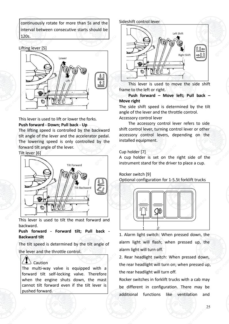
Rocker switch [9]
Optional configuration for 1-5.5t forklift trucks
1. Alarm light switch: When pressed down, the
alarm light will flash; when pressed up, the
alarm light will turn off.
2. Rear headlight switch: When pressed down,
the rear headlight will turn on; when pressed up,
the rear headlight will turn off.
Rocker switches in forklift trucks with a cab may
be different in configuration. There may be
additional functions like ventilation and
Оригинальная страница: таблицы и схемы
Страница 30
26
demisting.
Standard configuration for 4-5.5t China IV
forklift trucks
Accelerator pedal [10]
When the accelerator pedal is pressed, the
engine speed and the forklift speed will increase;
when the accelerator pedal is released the
engine speed and the forklift speed will
decrease.
Brake pedal [11]
When the brake pedal is pressed the truck slows
down; when the brake pedal is pressed to the
bottom, the truck stops. When the pedal is
released the truck runs freely.
Caution
Avoid emergency braking. Emergency
braking can easily cause the truck to tilt or
cargo to fall, resulting in accidents.
Inching pedal [12]
When the pedal is pressed, the oil pressure of
the hydraulic clutch will drop. When the pedal is
pressed harder, the forklift truck will be braked.
The pedal can be used when the forklift truck
slows down to approach cargo or conducts
loading and unloading operations.
Caution
Do not use the inching pedal excessively. If
the pedal is used as a footrest or used for a
long time, it may cause overheating of the
automatic transmission oil or clutch slip.
Clutch pedal [12] (manual transmission)
Depress the clutch pedal to separate the engine
and transmission; release the clutch pedal to
transmit the power from the engine to the
transmission via the clutch.
Caution
Do not drive the forklift truck when the
clutch is not fully engaged.
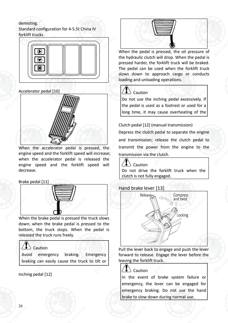
Hand brake lever [13]
Pull the lever back to engage and push the lever
forward to release. Engage the lever before the
leaving the forklift truck.
Caution
In the event of brake system failure or
emergency, the lever can be engaged for
emergency braking. Do not use the hand
brake to slow down during normal use.
Оригинальная страница: таблицы и схемы
Страница 31
27
Adjusting lever for steering wheel tilt angle [14]
14
The position of the steering wheel can be
adjusted. To perform adjustment, pull the
adjusting lever installed on the left side of the
steering hub column, move the steering wheel
to the desired position, and push down the
adjusting lever to lock.
Caution
a. Adjust the steering wheel tilt angle only
after the forklift truck has stopped and the
hand brake is engaged.
b. Forcibly move the steering wheel up and
down to ensure that it has been locked after
adjusting.
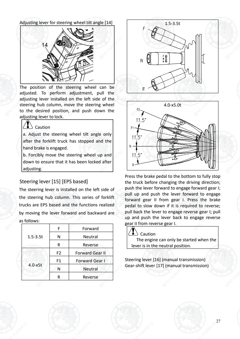
Steering lever [15] [EPS based]
The steering lever is installed on the left side of
the steering hub column. This series of forklift
trucks are EPS based and the functions realized
by moving the lever forward and backward are
as follows:
1.5-3.5t
F Forward
N Neutral
R Reverse
4.0-x5t
F2 Forward Gear II
F1 Forward Gear I
N Neutral
R Reverse
1.5-3.5t
4.0-x5.0t
Press the brake pedal to the bottom to fully stop
the truck before changing the driving direction;
push the lever forward to engage forward gear I;
pull up and push the lever forward to engage
forward gear II from gear I. Press the brake
pedal to slow down if it is required to reverse;
pull back the lever to engage reverse gear I; pull
up and push the lever back to engage reverse
gear II from reverse gear I.
Caution
The engine can only be started when the
lever is in the neutral position.
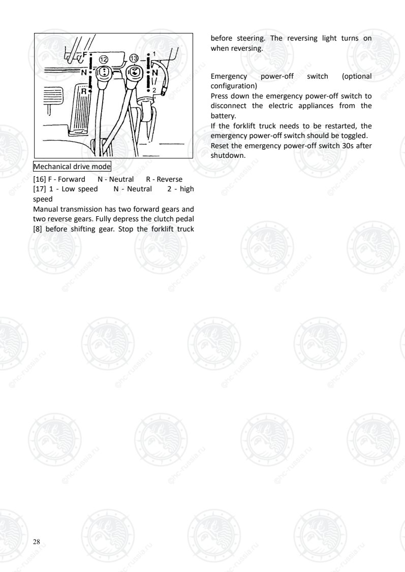
Steering lever [16] (manual transmission)
Gear-shift lever [17] (manual transmission)
Оригинальная страница: таблицы и схемы
Страница 32
28
Mechanical drive mode
[16] F - Forward N - Neutral R - Reverse
[17] 1 - Low speed N - Neutral 2 - high
speed
Manual transmission has two forward gears and
two reverse gears. Fully depress the clutch pedal
[8] before shifting gear. Stop the forklift truck
before steering. The reversing light turns on
when reversing.
Emergency power-off switch (optional
configuration)
Press down the emergency power-off switch to
disconnect the electric appliances from the
battery.
If the forklift truck needs to be restarted, the
emergency power-off switch should be toggled.
Reset the emergency power-off switch 30s after
shutdown.
Оригинальная страница: таблицы и схемы
Страница 33
29
4. Body and other parts
Load-backrest
The load-backrest ensures the stable loading of
cargo. The forklift truck must not be operated
without a load-backrest.
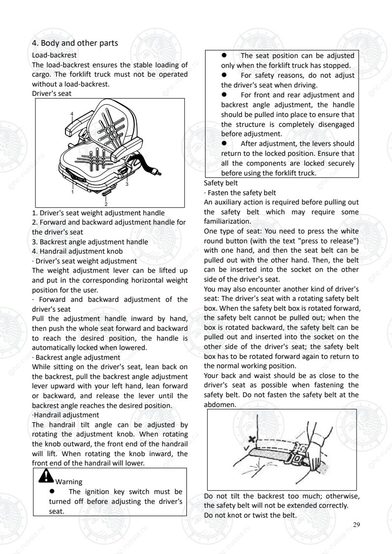
Driver's seat
1
2
3
4
1. Driver's seat weight adjustment handle
2. Forward and backward adjustment handle for
the driver's seat
3. Backrest angle adjustment handle
4. Handrail adjustment knob
· Driver's seat weight adjustment
The weight adjustment lever can be lifted up
and put in the corresponding horizontal weight
position for the user.
· Forward and backward adjustment of the
driver's seat
Pull the adjustment handle inward by hand,
then push the whole seat forward and backward
to reach the desired position, the handle is
automatically locked when lowered.
· Backrest angle adjustment
While sitting on the driver's seat, lean back on
the backrest, pull the backrest angle adjustment
lever upward with your left hand, lean forward
or backward, and release the lever until the
backrest angle reaches the desired position.
·Handrail adjustment
The handrail tilt angle can be adjusted by
rotating the adjustment knob. When rotating
the knob outward, the front end of the handrail
will lift. When rotating the knob inward, the
front end of the handrail will lower.
Warning
The ignition key switch must be
turned off before adjusting the driver's
seat.
The seat position can be adjusted
only when the forklift truck has stopped.
For safety reasons, do not adjust
the driver's seat when driving.
For front and rear adjustment and
backrest angle adjustment, the handle
should be pulled into place to ensure that
the structure is completely disengaged
before adjustment.
After adjustment, the levers should
return to the locked position. Ensure that
all the components are locked securely
before using the forklift truck.
Safety belt
· Fasten the safety belt
An auxiliary action is required before pulling out
the safety belt which may require some
familiarization.
One type of seat: You need to press the white
round button (with the text "press to release")
with one hand, and then the seat belt can be
pulled out with the other hand. Then, the belt
can be inserted into the socket on the other
side of the driver's seat.
You may also encounter another kind of driver's
seat: The driver's seat with a rotating safety belt
box. When the safety belt box is rotated forward,
the safety belt cannot be pulled out; when the
box is rotated backward, the safety belt can be
pulled out and inserted into the socket on the
other side of the driver's seat; the safety belt
box has to be rotated forward again to return to
the normal working position.
Your back and waist should be as close to the
driver's seat as possible when fastening the
safety belt. Do not fasten the safety belt at the
abdomen.
Do not tilt the backrest too much; otherwise,
the safety belt will not be extended correctly.
Do not knot or twist the belt.
Оригинальная страница: таблицы и схемы
Страница 34
30
Keep the safety belt fastened tightly during daily
operation to protect yourself and reduce injury
if the truck rolls over.
·Unfasten the safety belt
Press the red button (with the text "PRESS") on
the socket with your left thumb to unfasten the
safety belt.
·Check the safety belt
Frequently check whether the bolt to fix the
safety belt is secure. Do not press the safety belt
on hard or fragile objects and do not rub the
safety belt with sharp objects to avoid damage.
Do not disassemble components on the safety
belt without permission. Visual inspections
should be routinely conducted for belts that
have been used frequently.
Cutting or fraying;
Wear or damage of metal parts, including
the locating point;
Buckle or retractor fault;
Damage.
If any abnormality is found, a new belt should be
fitted immediately; the service life of the belt is
3 years; if any abnormality is found, the belt
should be replaced in advance.
Overhead guard
The overhead guard protects the operator
from falling objects. It must have sufficient
impact strength. The forklift truck must not be
used without an overhead guard.
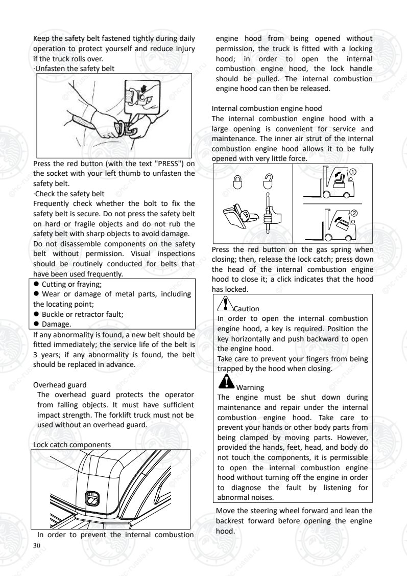
Lock catch components
In order to prevent the internal combustion
engine hood from being opened without
permission, the truck is fitted with a locking
hood; in order to open the internal
combustion engine hood, the lock handle
should be pulled. The internal combustion
engine hood can then be released.
Internal combustion engine hood
The internal combustion engine hood with a
large opening is convenient for service and
maintenance. The inner air strut of the internal
combustion engine hood allows it to be fully
opened with very little force.
1
2
WARNING
Press the red button on the gas spring when
closing; then, release the lock catch; press down
the head of the internal combustion engine
hood to close it; a click indicates that the hood
has locked.
Caution
In order to open the internal combustion
engine hood, a key is required. Position the
key horizontally and push backward to open
the engine hood.
Take care to prevent your fingers from being
trapped by the hood when closing.
Warning
The engine must be shut down during
maintenance and repair under the internal
combustion engine hood. Take care to
prevent your hands or other body parts from
being clamped by moving parts. However,
provided the hands, feet, head, and body do
not touch the components, it is permissible
to open the internal combustion engine
hood without turning off the engine in order
to diagnose the fault by listening for
abnormal noises.
Move the steering wheel forward and lean the
backrest forward before opening the engine
hood.
Оригинальная страница: таблицы и схемы
Страница 35
31
Return the steering wheel and backrest to
original positions after closing the engine
hood.
②
①
Water tank cover plate
The water tank cover plate can be removed
when the internal combustion engine hood is
closed to check the coolant quantity.
Caution
Reinstall the water tank cover plate and
fasten the bolt with your hands.
Trucks exported to Europe should be fixed with
a hexagon bolt; before moving, it should be
released with a socket spanner; the bolt should
be tightened with a socket spanner during
reinstallation
Water tank lid and additional water tank
The additional water tank is in the internal
combustion engine hood.
The water tank lid is under the rear cover plate
of the internal combustion engine hood.
Warning
· Do not open the water tank lid when the
engine water temperature is higher than 70
℃. Press the lid down and slightly rotate it
to the left to reduce the pressure in the
water tank.
· Do not open the water tank lid when
wearing gloves.
· The antifreeze is corrosive and toxic and
should be rinsed off when your skin and
body are exposed to it. Keep children away
from the antifreeze.
Fork positioning pin
It is used when adjusting the fork spacing. Pull
out the stop dowel, rotate by 180°, and adjust
the forks to the required position for the cargo
to be unloaded.
1
2
3
Warning
The fork spacing adjustment should be
based on the center line of the forklift
truck and symmetrical on the left and right
sides; the stop dowel should be tight after
adjusting.
There is an opening on the lower beam of
the fork arm carrier for loading and
unloading forks.
Do not use the fork in the open position to
prevent the fork from falling off from the
open position. Regularly check the bolt in
the middle of the fork arm, which prevents
the fork from being used in the open
position.
Step and handrail for getting on and off the
forklift truck
The body is provided with a step for getting on
and off on both sides; the handrails are installed
on the left and right pillars of the overhead
guard. Please use the handrails for safety when
getting on and off the forklift truck.
Оригинальная страница: таблицы и схемы
Страница 36
32
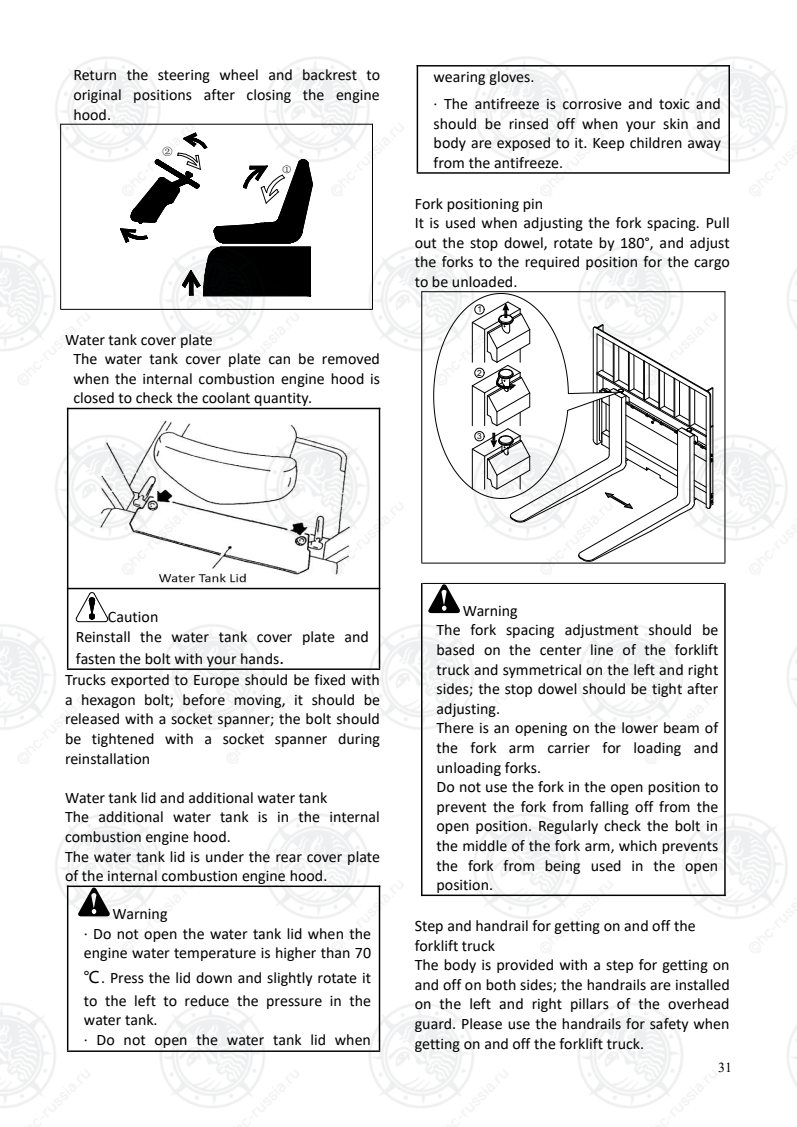
Hydraulic oil tank lid
The hydraulic oil tank lid is on the right frame of
the internal combustion engine hood that can
be opened when refilling. Replenish with clean
hydraulic oil through the oil filling port and
screw down the lid after refilling.
Fuel tank lid
Fuel tank lid without a lock
Fuel tank lid with a lock (LPG single-fuel
trucks only)
The fuel tank lid is on the left rear side of the
body. There is a vent in the fuel oil tank and the
vent should be checked for blockages when
refuelling.
Note: Do not pour the gasoline into the fuel
tank, because gasoline is not used for the LPG
single-fuel trucks. To prevent the incorrect fuel
being added, the fuel tank lid is equipped with a
lock.
Caution
1. When refueling, the forklift truck
must be stopped, the engine must be shut
down, and the hand brake lever must be
engaged; the driver must get off and there
should be no naked flames nearby.
2. The lid has to be screwed down after
refuelling; otherwise the fuel will leak, which
may result in a fire.
3. The engine can be started only after
wiping up the spilled fuel.
4. Naked flames are prohibited when
checking the fuel level.
Mirror
A mirror is installed on the upper right of the
overhead guard for observing conditions behind
the truck or when reversing.
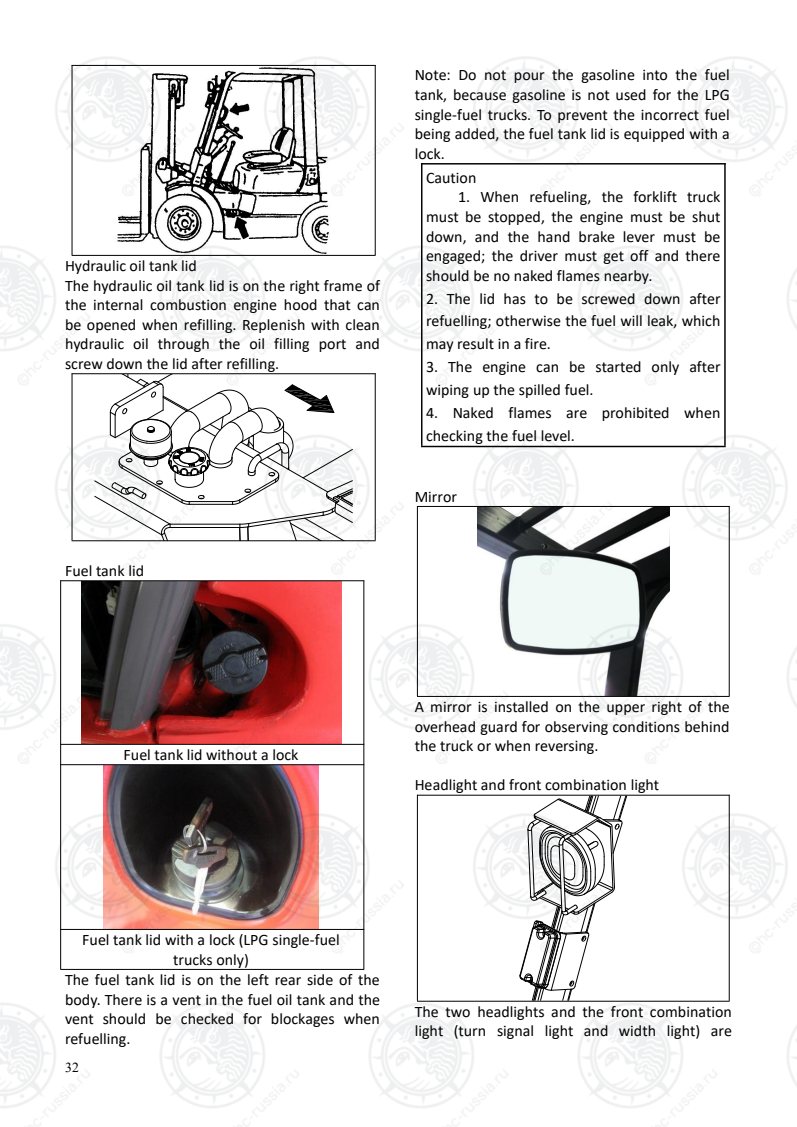
Headlight and front combination light
The two headlights and the front combination
light (turn signal light and width light) are
Оригинальная страница: таблицы и схемы
Страница 37
33
mounted on the front support of the overhead
guard. Pay attention to the protecting lights; if
there is any dust, they should be wiped clean; if
there is any damage, they should be replaced.
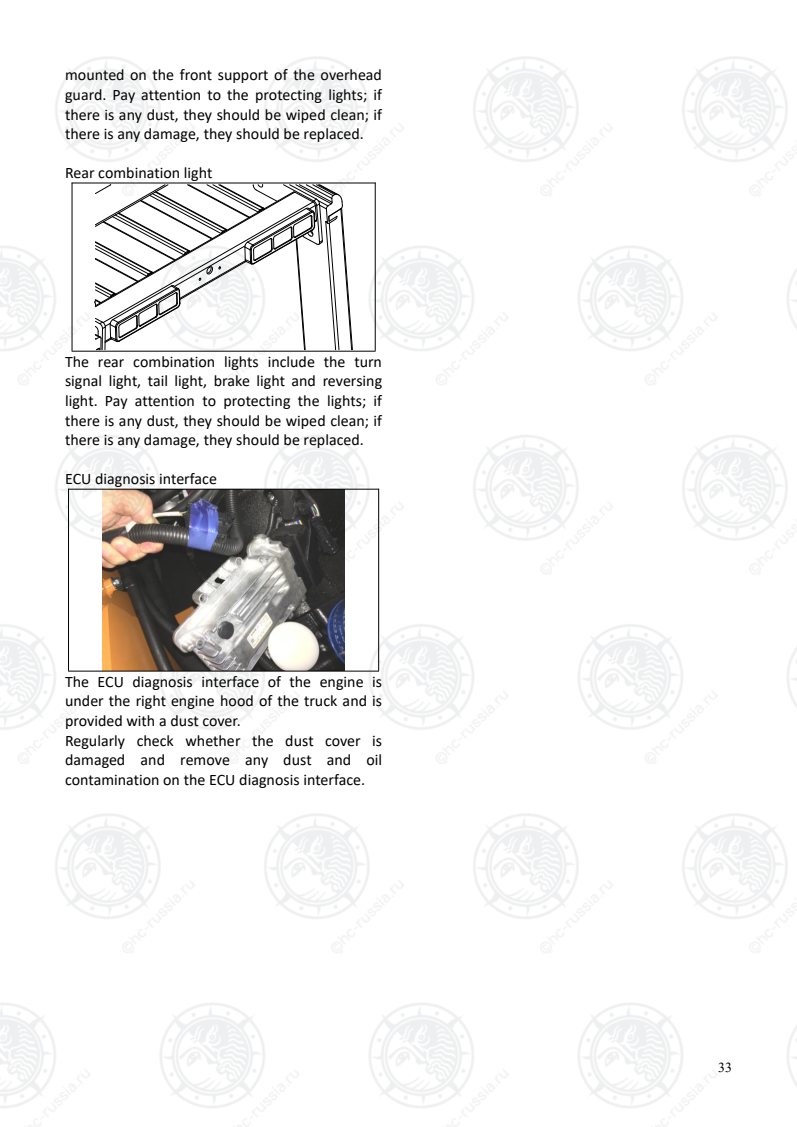
Rear combination light
The rear combination lights include the turn
signal light, tail light, brake light and reversing
light. Pay attention to protecting the lights; if
there is any dust, they should be wiped clean; if
there is any damage, they should be replaced.
ECU diagnosis interface
The ECU diagnosis interface of the engine is
under the right engine hood of the truck and is
provided with a dust cover.
Regularly check whether the dust cover is
damaged and remove any dust and oil
contamination on the ECU diagnosis interface.
Оригинальная страница: таблицы и схемы
Страница 38
34
III. Safety regulations
1. Only trained and approved operators can
operate the forklift truck.
2. Oil/water leakage, deformation and
looseness should be regularly checked;
otherwise, the service life of the truck will be
shortened; in severe cases, it may cause an
accident.
Ensure that “key safety parts” are replaced in
regular checks.
Wipe off oil, grease or water on the baseplate,
pedal and control lever.
Shut down the engine, especially the fan when
checking the engine and associated parts.
Take care to avoid scalding when checking the
water tank or silencer.
3. Whenever the truck is found to be faulty,
you should stop operations and report the
condition to the management personnel.
During maintenance at height (such as the
mast, front light and back light), take care to
avoid getting trapped and slipping.
If the alarm indicator light turns on or in case
of any other fault, the truck should be driven to
a safe place for checks or troubleshooting.
Protect your hands, head and body from
scratching at corners and sharp edges you may
touch during maintenance and repair.
Hang the “fault” sign on the truck as a
reminder.
4. Do not check the fuel oil level, electrolyte,
cooling water and leakages when there is a
naked flame nearby.
Do not smoke to avoid explosions when
checking the battery, refilling with fuel oil or
checking the fuel oil system.
The workplace should be provided with a fire
extinguisher.
Do not refuel when the engine is running.
5. Warm up the forklift truck until the water
temperature is 70℃ before operation.
Do not open the water tank lid when the water
temperature is higher than 70℃.
6. The exhaust gas (carbon monoxide - CO) is
harmful to the human body; there should be
sufficient ventilation when the forklift truck is
operated in an enclosed space; and an exhaust
fan should be provided if necessary.
Caution
The truck should not be used in flammable
and explosive environments.
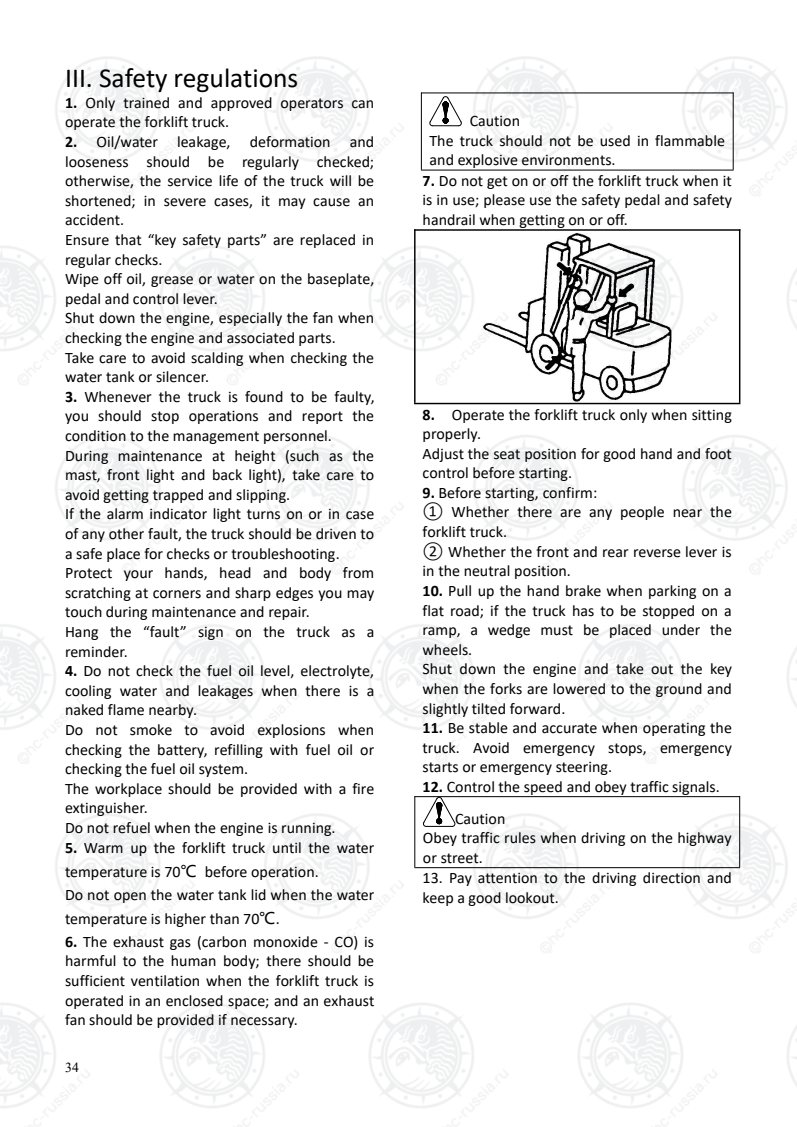
7. Do not get on or off the forklift truck when it
is in use; please use the safety pedal and safety
handrail when getting on or off.
8. Operate the forklift truck only when sitting
properly.
Adjust the seat position for good hand and foot
control before starting.
9. Before starting, confirm:
① Whether there are any people near the
forklift truck.
② Whether the front and rear reverse lever is
in the neutral position.
10. Pull up the hand brake when parking on a
flat road; if the truck has to be stopped on a
ramp, a wedge must be placed under the
wheels.
Shut down the engine and take out the key
when the forks are lowered to the ground and
slightly tilted forward.
11. Be stable and accurate when operating the
truck. Avoid emergency stops, emergency
starts or emergency steering.
12. Control the speed and obey traffic signals.
Caution
Obey traffic rules when driving on the highway
or street.
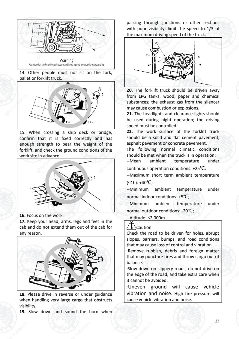
13. Pay attention to the driving direction and
keep a good lookout.
Оригинальная страница: таблицы и схемы
Страница 39
35
14. Other people must not sit on the fork,
pallet or forklift truck.
15. When crossing a ship deck or bridge,
confirm that it is fixed correctly and has
enough strength to bear the weight of the
forklift, and check the ground conditions of the
work site in advance.
16. Focus on the work.
17. Keep your head, arms, legs and feet in the
cab and do not extend them out of the cab for
any reason.
18. Please drive in reverse or under guidance
when handling very large cargo that obstructs
visibility.
19. Slow down and sound the horn when
passing through junctions or other sections
with poor visibility; limit the speed to 1/3 of
the maximum driving speed of the truck.
20. The forklift truck should be driven away
from LPG tanks, wood, paper and chemical
substances; the exhaust gas from the silencer
may cause combustion or explosions.
21. The headlights and clearance lights should
be used during night operation; the driving
speed must be controlled.
22. The work surface of the forklift truck
should be a solid and flat cement pavement,
asphalt pavement or concrete pavement.
The following normal climatic conditions
should be met when the truck is in operation:
--Mean ambient temperature under
continuous operation conditions: +25℃;
--Maximum short term ambient temperature
(≤1h): +40℃;
--Minimum ambient temperature under
normal indoor conditions: +5℃;
--Minimum ambient temperature under
normal outdoor conditions: -20℃;
--Altitude: ≤2,000m.
Caution
Check the road to be driven for holes, abrupt
slopes, barriers, bumps, and road conditions
that may cause loss of control and vibration.
·Remove rubbish, debris and foreign matter
that may puncture tires and throw cargo out of
balance.
·Slow down on slippery roads, do not drive on
the edge of the road, and take extra care when
it cannot be avoided.
·Uneven ground will cause vehicle
vibration and noise. High tire pressure will
cause vehicle vibration and noise.
Оригинальная страница: таблицы и схемы
Страница 40
36
Warning
Do not use the forklift truck in sand, snow,
lightning, rain, wind and other bad weather
conditions.
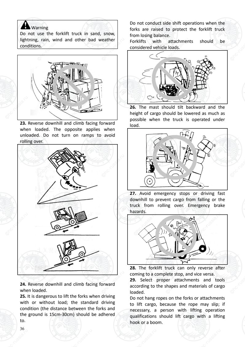
23. Reverse downhill and climb facing forward
when loaded. The opposite applies when
unloaded. Do not turn on ramps to avoid
rolling over.
24. Reverse downhill and climb facing forward
when loaded.
25. It is dangerous to lift the forks when driving
with or without load; the standard driving
condition (the distance between the forks and
the ground is 15cm-30cm) should be adhered
to.
Do not conduct side shift operations when the
forks are raised to protect the forklift truck
from losing balance.
Forklifts with attachments should be
considered vehicle loads.
26. The mast should tilt backward and the
height of cargo should be lowered as much as
possible when the truck is operated under
load.
27. Avoid emergency stops or driving fast
downhill to prevent cargo from falling or the
truck from rolling over. Emergency brake
hazards.
28. The forklift truck can only reverse after
coming to a complete stop, and vice versa.
29. Select proper attachments and tools
according to the shapes and materials of cargo
loaded.
Do not hang ropes on the forks or attachments
to lift cargo, because the rope may slip; if
necessary, a person with lifting operation
qualifications should lift cargo with a lifting
hook or a boom.
Оригинальная страница: таблицы и схемы
Страница 41
37
Caution
Do not let the forks touch the road surface to
avoid damaging the fork tip and road surface.
30. Know the load curves of the forklift truck
and attachments, and do not overload. It is
very dangerous to use artificial additional
counterweights.
31. The overhead guard can protect you from
being hit by falling cargo. The load-backrest
ensures the stable loading of cargo. Forklifts
should not be used without overhead guards
and load-backrests.
32. Do not stand or walk under the forks or
attachments.
Do not stand on the fork.
33. Do not place your head or body between
the mast and the overhead guard. You may be
injured if your head or body is trapped.
Do not stretch your hands between the inner
mast and the outer mast.
34. When the noise near the driver's ear is
greater than 80dB, the driver should take
hearing protection measures.
Caution
Rough or bumpy working surfaces and high tire
deformation will increase the noise level.
35. Enter the area from the front and carefully
insert the forks into the pallet when taking
cargo from the stack.
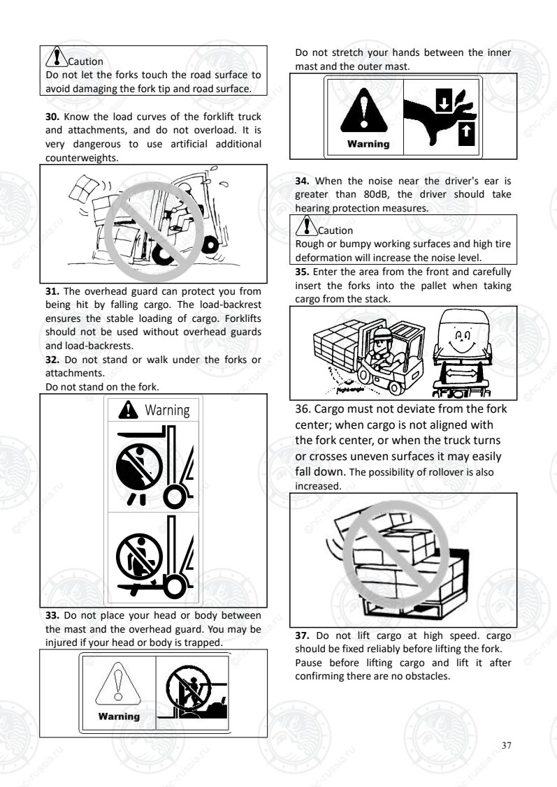
36. Cargo must not deviate from the fork
center; when cargo is not aligned with
the fork center, or when the truck turns
or crosses uneven surfaces it may easily
fall down. The possibility of rollover is also
increased.
37. Do not lift cargo at high speed. cargo
should be fixed reliably before lifting the fork.
Pause before lifting cargo and lift it after
confirming there are no obstacles.
Оригинальная страница: таблицы и схемы
Страница 42
38
38. Ensure that the cargo is tied firmly and
placed flat on the two forks; do not lift cargo
with a single fork.
For forklift trucks with attachments (like flat
holding clamps), cargo should be tied firmly
and clamped; the multiway valve control lever
should then be pulled into place.
39. Do not lift cargo when the forklift truck is
on a slope and avoid loading and unloading
operations on ramps.
40. The stacking height of the cargo should not
exceed that of the load-backrest; if it cannot be
avoided, the cargo should be fixed firmly.
Please drive in reverse or under guidance when
handling large cargo obstructing visibility.
41. Reduce the forward tilt angle as much as
possible when stacking for unloading; when
the height of cargo is slightly higher or lower
than that of the stacking layer, cargo can tilt
forward.
When stacking at height and the distance to
the ground is 15cm-20cm, the mast should be
vertical and then lifted; be careful to not tilt
the mast when the cargo is lifted.
When picking up goods at height, insert the
fork into the pallet, slowly lift, back up and
then descend, lower the rear mast and tilt it
backward. Never tilt the mast when the goods
are at height.
42. Do not tow a forklift truck with a faulty
engine, abnormal steering system or damaged
brake system.
Obey traffic rules when towing a forklift truck
on the highway.
43. Wear overalls and other personal safety
protective devices, such as earplugs, safety hat,
goggles, dust mask, safety shoes, anti-static
clothing etc. at work as appropriate; do not
wear a tie or attachments for your own safety.
44. The workplace should be provided with a
fire extinguisher. The user can choose to
provide a fire extinguisher for the truck, which
is generally installed on the rear leg of the
safety frame for easy access.
The driver and management personnel should
be familiar with the position and operation of
the fire extinguisher.
45. Use a pallet when handling small objects
and do not place them on the forks directly.
46. There are warnings and operation methods
on the truck labels. Please operate according to
the directions of the manual and truck labels.
Check labels, signs and marks, and replace
damaged or missing labels, signs and marks.
47. Various attachments are provided from
HANGCHA for the user, such as rotating clamps,
flat holding clamps, side shift forks, and booms,
which are to be used exclusively. If attachments
are required to be refitted, the permission of
the manufacturer must be obtained. Do not
refit your attachments without permission.
48. As improper use of a cell phone by the
driver will endanger life and property safety,
safety rules prohibit the driver from using a cell
phone: the use of cell phones or other
electronic communication devices unrelated to
the truck is prohibited during operation.
49.It is strictly prohibited to use two or more
forklifts to jointly transport the same object, as
this can easily lead to the forklifts overturning
or tipping over, potentially causing personal
injuries or fatalities.
Оригинальная страница: таблицы и схемы
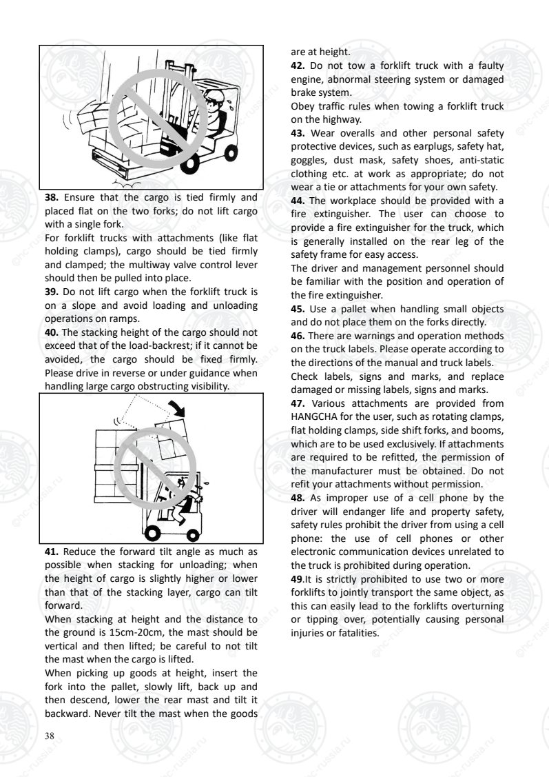
Страница 43
39
Warning
Exhaust fumes
The exhaust fumes from internal
combustion engines contain carbon
monoxide and other harmful chemicals.
Carbon monoxide is a colorless and
odorless toxic substance and can cause
loss of consciousness or death without any
symptoms. Long-term exposure to exhaust
fumes or emission chemicals may cause
cancer, birth defects and other
reproductive harm. Avoid exposure to
engine exhaust fumes.
If the engine is operating in an enclosed
space, proper ventilation should be
provided and the exhaust fumes should be
vented to the outside. Do not exceed the
acceptable air pollutant limits.
Follow the inspection and maintenance
schedules and procedures in this manual
and the engine manual. Do not modify or
refit the emissions, ignition or fuel system.
Warning
Fire risk
If there are flammable gases, vapors,
liquids, dust or fibers in the operating area
of internal combustion engined forklift
trucks, fires may be caused when the hot
engine surface and exhaust fumes are
exposed to them. The surface temperature
of engine and exhaust parts may exceed
the ignition temperatures of common
solvents, fuel oil, engine oil, paper and
other organic materials (wood, agricultural
weeds/grains, cotton and wool, etc).
Sparks from exhaust fumes can also ignite
these materials. The surface temperature
of the engine and exhaust pipe will rise
after the engine is turned off, thus the risk
of fires may be increased. The engine
compartment should be inspected
immediately after the forklift truck was
operated in an area containing flammable
dust, fibers or paper, and all debris should
be removed.
Оригинальная страница: таблицы и схемы
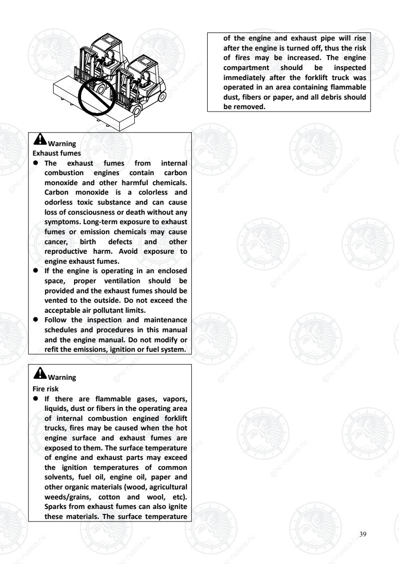
Страница 44
40
IV. Maintenance
For more detailed maintenance information,
please refer to the Regular Maintenance and
Lubrication Cycle Table.
1. Daily maintenance (8 hours)
Daily maintenance also doubles as a pre-drive
inspection.
1. Leakage check: Electrolyte, hydraulic oil,
cooling liquid and hydraulic transmission oil
Warning
Do not drive the truck if a fuel leak is found
before work; start the engine only after
eliminating the leakage.
Check whether there are any fuel leaks or
water leaks in the engine, hydraulic pipe
connectors, water tank and drive system by
hand and visual inspection.
2. Visual inspection
Check whether lights and instruments work
normally.
Check tires, air pressure and bolts for
looseness.
Check whether the tires are damaged and
whether tire pressures are normal.
3. Fuel quantity check
The fuel gauge is installed on the instrument
panel to check the fuel level everyday before
work. Fill up the fuel tank every day after work.
The fuel filler is on the left leg of the overhead
guard.
4. Engine oil level check
Caution
·The forklift truck must placed on a flat
surface to conduct the oil level check.
· When the engine has cooled, the level can
be checked accurately.
Pull out the oil dipstick first, wipe the scale
head, reinsert it and pull it out to check
whether the oil level is between the two scale
marks.
5. Engine coolant quantity check
Check the coolant level in the additional water
tank when the engine is cool. If it is lower than
“MIN”, it should be supplemented to “MAX”. If
there is no coolant in the additional water tank,
the coolant quantity in the main water tank
should be checked. If the coolant quantity in
the main water tank is insufficient, coolant
with a freezing point of -36.5℃ should be
added to the water tank lid; the coolant should
be supplemented to the “MAX” level of the
additional water tank.
Caution
The water added to the water tank should
be clean tap water. If antifreeze is used, the
same antifreeze should be added.
Pay special attention to the water tank and
cooling system in hot seasons.
Оригинальная страница: таблицы и схемы
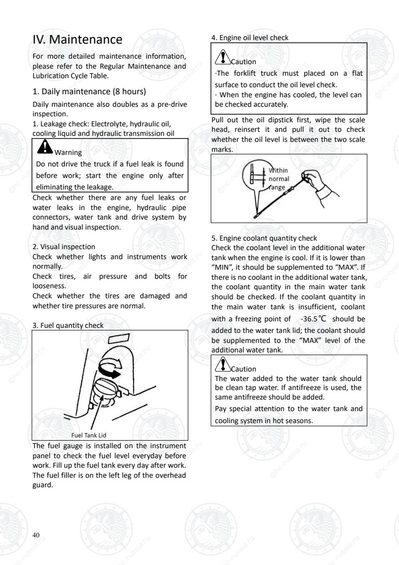
Страница 45
41
Warning
·Do not open the water tank lid when the
engine water temperature is higher than
70℃. Press the lid and slowly turn to the
left to allow the steam to escape, place a
thin cloth around the lid and unscrew it.
·Do not screw the water tank lid with
gloves to avoid being scalded by high
pressure hot water.
·Antifreeze contains substances harmful to
the human body. If you swallow it by
accident, you should induce vomiting
immediately and go to hospital.
· Keep children away from the antifreeze.
6.Hydraulic oil tank level check
Check the oil level in the hydraulic oil tank
1. The scale line “L” marks the lower limit of
the hydraulic oil level, and the hydraulic oil
level must be higher than this scale line for
trucks with a mast no greater than 4 m.
2. The scale line “M” marks the lower limit of
the high mast, and the hydraulic oil level must
be higher than this scale line for trucks with a
mast over 4 m and trucks equipped with
attachments.
3. The scale line “H” marks the upper limit of
hydraulic oil level, but it may be higher than
this limit for trucks equipped with
attachments.
7. Brake fluid quantity check (1.0t-X5.0t)
Check the brake fluid reservoir. Check whether
the brake fluid quantity is within the scale; if
the liquid quantity is insufficient, please top it
up and check whether there is air in the brake
line.
Caution
Prevent dust and water from mixing with the
brake fluid when adding it.
Brake fluid is toxic and corrosive and should
be rinsed off if you are exposed to it.
Replacement of brake fluid
See the Daily maintenance (1000 hours)
8. Light check
Ensure that the light turns on when the ignition
key switch is on.
9. Indicator light check
Toggle the indicator light control lever and
check whether the indicator light operates
normally.
10. Hand brake check
① The truck slows down.
② The truck brakes and stops when the hand
brake lever is pulled up. The truck must not
deviate.
11. Reversing light and reversing buzzer check
When the shift lever is in the R position, the
reversing light turns on and the reversing
buzzer sounds.
12. Steering
① The truck should be driven slowly.
② Turn the steering wheel three turns
clockwise and anticlockwise, respectively.
Check whether the left and right steering force
are the same.
13. Horn
Press the horn button and check whether the
sound is normal.
14. Seat adjustment and safety belt check
Pull the seat adjusting lever back, adjust the
Оригинальная страница: таблицы и схемы
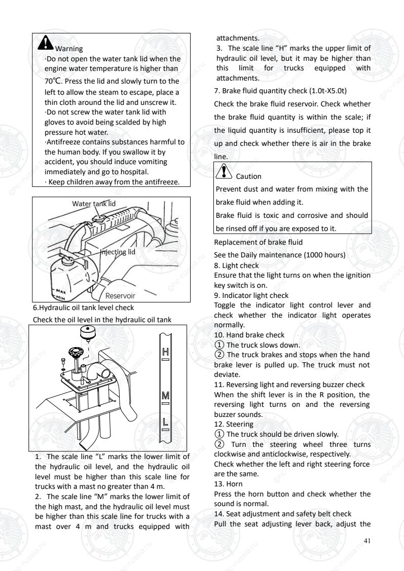
Страница 46
42
driver's seat to a comfortable position for your
hands and feet, release the seat adjusting lever,
and lock it.
Check whether the safety belt works normally.
15. Shift lever
Check whether the shift lever is loose and
whether it is stable when shifting gear.
16. Lift lever, tilt lever and accessory lever
Check that the lift lever, tilt lever and accessory
lever are secure and they return properly.
Increase the engine speed, respectively
operate the lift lever, tilt lever, and accessory
lever, and ensure that the forks can be fully
lifted and lowered and the mast can tilt
forward and backward.
17. Instruments and sensors
Check whether the stopwatch,
water-thermometer, oil thermometer,
transmission oil temperature sensor, fuel
sensor, engine water temperature sensor, oil
pressure sensor and others are normal.
18. Clutch pedal, brake pedal and inching pedal
Depress the clutch pedal to make it fully
disengage.
Slow down and step on the brake pedal; after
stepping on the brake pedal, the brake light
should turn on.
Slow down and step on the inching pedal;
check whether the inching pedal function is
normal.
19. Tire check and tire pressure check
Screw the cap back on after confirming that
there is no air leakage; check whether there is
damage on the tire surfaces and sides and
whether the rims are deformed.
Unscrew the cap anticlockwise and measure
the tire pressure with an air pressure gauge.
Increase the pressure to the specified value if
it is insufficient.
Warning
The forklift truck tires require very high
pressure to bear loads; tiny deformation of
the rim or surface damage to the tire may
cause an accident.
When using an air compressor, as the
maximum output pressure of the air
compressor is higher than the specified
pressure of tire, the pressure setting should be
adjusted first, see the following table for
pressure values; over pressurizing may cause a
serious accident.
In order to ensure safety, the tire should be
placed in a protective frame during air
inflation.
Tire pressures should adopt the new standard
GB/T2982-2014:
Model Driving wheel
(front wheel)
Steering wheel
(rear wheel)
1t-1.8t 790kPa 1000kPa
2t-2.5t 860kPa 860kPa
3t-3.5t 830kPa 790kPa
4t-X5t 830kPa 860kPa
5.5t 930kPa 860kPa
Оригинальная страница: таблицы и схемы
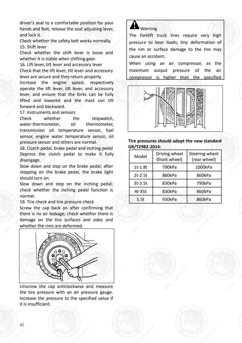
Страница 47
43
2. Weekly maintenance (40 hours)
Add the following maintenance items in
addition to daily maintenance.
1. Air filter maintenance
In general: Please service the filter after the
truck has been operated for 50-250 hours.
Please replace the filter after six maintenance
cycles.
Caution
If the truck is used in harsh working
conditions, the maintenance and
replacement cycle of the filter should be
more frequent.
For trucks in a harsh working environment with
a large amount of dust, the maintenance and
replacement cycle should be shortened
according to the actual situation, and it is
recommended to maintain the filter every 8-50
hours and replace it with a new one every
100-300 hours.
Maintenance procedures for 1.0t-X5.5t trucks:
1 Remove the end cover of the air filter.
2 Remove the main filter cartridge and the
safety filter cartridge and then separate them.
3 The main filter cartridge is the outer filter
cartridge. Blow out the dust inside and outside
the main filter cartridge with compressed air.
4 The safety filter cartridge is the inner filter
cartridge: clean it by tapping with your hand,
but not by blowing with air. Special attention
should be paid to this requirement.
Warning
1、 Airborne dust may get into your eyes, so
protective glasses should be used before
blowing.
2、 Failure to maintain and replace the filter
cartridges on time as required will lead to
early engine damage.
For forklift trucks equipped with air filter
maintenance indicators (optional):
Scale line: Engine air intake resistance
Viewing
window
Engine air intake resistance
Yellow
No air intake resistance, no
maintenance needed
currently.
Yellow + Red Slight air intake resistance,
maintenance needed
Red
or the air
pressure is
larger than
6.2kPa
Severe air intake
resistance, maintenance
required or replace the
main filter cartridge
Оригинальная страница: таблицы и схемы
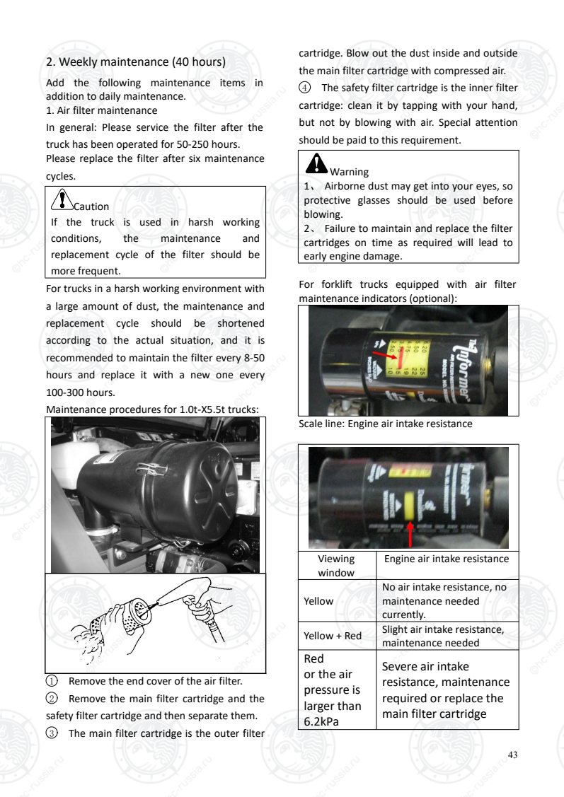
Страница 48
44
① It is not necessary to remove all the filter
cartridges during the maintenance of the main
filter cartridge since the safety filter cartridge
does not need any maintenance.
② If the main cartridge has been serviced 3
times or the viewing window still shows red
after the maintenance, the main filter cartridge
and the safety filter cartridge need to be
replaced at the same time.
③ After maintaining or replacing the filter
cartridges, please press the reset button on the
top to reset the viewing window.
Maintenance procedures for 4.0t-X5.0t W58
trucks:
① Unlock 4 buckles on the access lid of the air
filter.
② Hold the buckles with your hands and pull
the access lid outward to open it.
③ Slightly shake the main cartridge with your
hands and slowly take it out.
④ It is not necessary to service the safety
filter cartridge. Replace the safety filter
cartridge: Slightly shake it with your hands and
slowly take it out.
⑤ Clean the two inner sides of the housing
with a cloth to ensure it is properly mounted
and sealed.
⑥ Check the safety filter cartridge and mount
it into the housing.
⑦ Check the main filter cartridge and mount
it into the housing.
⑧ Mount the lid with the dust cap downward.
⑨ Lock the buckles to complete the assembly.
Warning
Failure to maintain and replace the filter
cartridges on time as required will lead to
early engine damage.2.Fan belt
Shut the engine down.
Use your finger to apply 10kg force downward
in the middle of the two pulleys to check
whether the deflection complies with the
specified value.
Оригинальная страница: таблицы и схемы
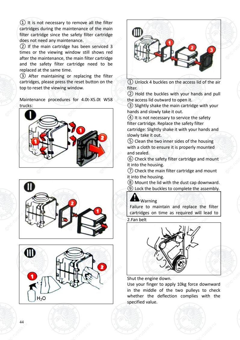
Страница 49
45
Engine Deflection (mm)
1.0t-3.5t
K21, K25 11-13
4TNE92
4TNE98
New 8-12 (<5min)
Old 10-14 (≥5min)
4TNV94L New 5-8 (<5min)
Old 7-10 (≥5min)
C240 8-12
S4S 12
Use your finger to apply 4 kg - 5kg force
downward in the middle of the two pulleys to
check whether the deflection complies with
the specified value.
Engine Deflection (mm)
4D27XG31
4D32XG31
4D32RG30
4D32XG40
CY4BG531
4D35Y41
YCF3657-T480
C490BPG-416
10-15
Use your finger to apply 6kg force downward in
the middle of the two pulleys to check whether
the deflection complies with the specified
value.
Engine Deflection (mm)
GM4.3L ≤13
Perkins 1104D engine: check items
A suitable gauge should be used to accurately
check the belt tension.
Place the belt tension meter (1) in the center of
the longest free length to measure its tension.
The correct tension of a new belt is 535N. If the
belt tension is lower than 250N, please adjust
it to 535N.
If two belts are used, please check and adjust
the tension of them both.
Perkins 1104D engine: adjustment
1. Loosen the AC generator pivot bolt (2) and
(3).
2. Move the AC generator to increase or reduce
the belt tension. Tighten the AC generator
pivot bolts and connecting rod bolts with a
torque of 22N.m.
QSB3.3, QSB4.5, QSF2.8 and F2.8CS449
Cummins engines are equipped with
auto-tensioning pulleys, so it is not necessary
to adjust the fan belt tension.
Caution
If the belt has been stretched beyond the
adjustment margin or is cut or cracked, it
should be replaced.
The belt deflection can only be checked when
the engine is stopped to prevent fingers from
being trapped or clothing being caught by the
machine.
3. Oil level of hydrodynamic transmission
Open the inspection cover, pull out the level
scale and check whether the oil level is
between the scale range as required.
Оригинальная страница: таблицы и схемы
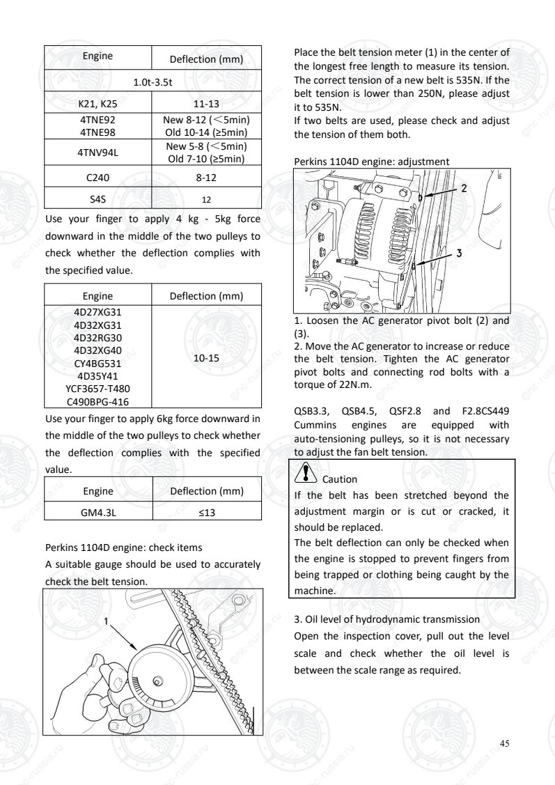
Страница 50
46
4. Mast and fork inspection
Check the mast and forks to ensure that:
① The fork is not cracked or bent and firmly
and correctly mounted on the fork arm.
② Check the oil cylinder and oil pipe for any
oil leakage.
③ Check the rotation of the rollers.
④ Check the mast for cracks and
deformation.
⑤ Manipulate the lifting, tilting, and metal
handle to check whether the mast works
normally and whether there is any abnormal
noise.
5. Chain tension check
① Raise the fork by 10cm-15cm with the
mast vertical.
② Press the middle of the chain with your
thumb to check whether the tension of the
left and right chains are the same.
③ Tension adjustment: loosen locknut 1,
screw nut 2 to adjust the chains so that the
tension of the two chains are the same, and
then tighten locknut 1.
6. Lubrication of the mast
According to the requirements of the regular
maintenance and lubrication cycle, the
following parts should be lubricated regularly.
① The lubrication cycle should be changed
according to the operating conditions. In the
busy months of operation, the lubrication cycle
should be shortened.
② In order to ease the forklift operation,
apply a layer of grease to the contact surface of
the lifting guide wheel and the inner & outer
mast.
Mast
Оригинальная страница: таблицы и схемы
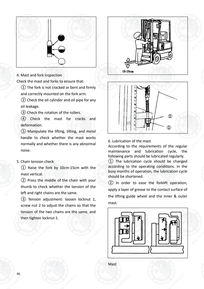
Страница 51
47
Apply a layer of grease on the supporting guide
rails.
Warning
When applying grease, park the forklift on a
flat road, turn off the engine and engage the
hand brake. Take care to avoid your hands and
body from being caught when lubricating, and
take care to avoid falling when lubricating at
high level.
7. Chain lubrication
Use a brush dipped in engine oil to lubricate
the chains on the left and right sides.
8. For the lubrication of the following parts, see
the Lubrication System Diagram for details.
① Lubrication of mast seat bearing;
② Lubrication of inching brake pedal;
③ Lubrication of steering axle support shaft;
④ Lubrication of steering knuckle spindle;
⑤ Lubrication of steering linkage pin;
⑥ Lubrication of steering cylinder pin.
9. Bolt and nut tightening
See the maintenance cycle table.
10.Tire nut tightening torque check
Check whether the tightening torque of the
wheel nuts meets the requirements.
Driving wheel (front wheel)
① Wheel nuts; ② Split rim bolts (only
applicable for 1-1.8t forklift trucks); ③ Half
shaft bolts
Tonnage Tightening
torque (N·m)
Wheelnut
1.0t-1.8t 157-176
2.0t-3.5t 363-490
4.0t-X5.0t 441-558
Steering wheel (rear wheel)
5 Rear wheel nut;
Оригинальная страница: таблицы и схемы
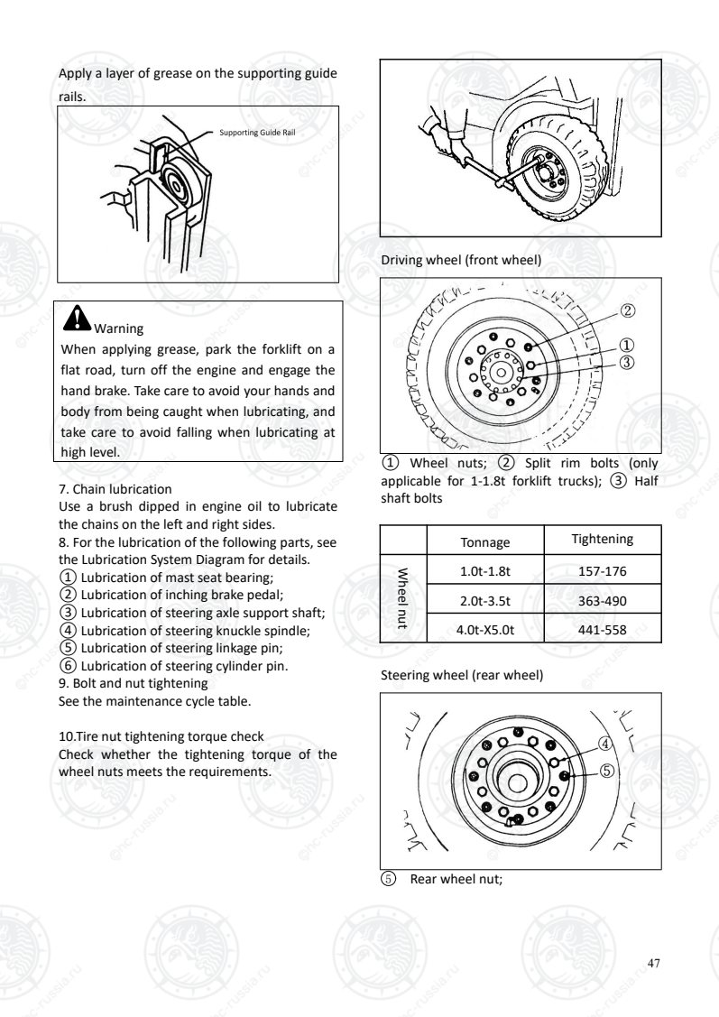
Страница 52
48
Tonnage Tightening
torque (N·m)
Wheelnut
1.0t-1.8t 78-98
2.0t-3.5t 157-176
4.0t-X5.0t 363-490
⑤ Split rear rim bolts.
11. Brake pedal, inching pedal and clutch check
With the engine still running, press the brake
pedal fully down, the distance between the
surface of the brake pedal and the floor should
be 60mm or more.
Check the height of the inching pedal and
clutch pedal in the same way.
1.0t-3.8t height and free clearance: mm
Height Free clearance Pedal idle
travel
Brake
pedal 1355 1-3 1-3
Inchi
ng
pedal
1355
Inching pedal
contact bolt -
brake pedal:
0mm
Clutc
h
pedal
1355 2-5 30-40
4.0-X5.0t height and free clearance: mm
Height Free clearance Pedal idle
travel
Brake
pedal 1405 1-3 1-3
Inchi
ng
pedal
1405
Inching pedal
contact bolt -
brake pedal:
0mm
Clutc
h
pedal
1405 2-5 24-30
12. Hand brake
Make sure the hand brake handle acts normally
after it is tightened and then loosened to its
original position.
1.0t-X5.0t Tension requirement: 245N-295N
13.Cylinder frame (LPG trucks only)
Pull the cylinder outward to check whether its
frame is secure and put it back to check
whether it is fixed safely.
Оригинальная страница: таблицы и схемы
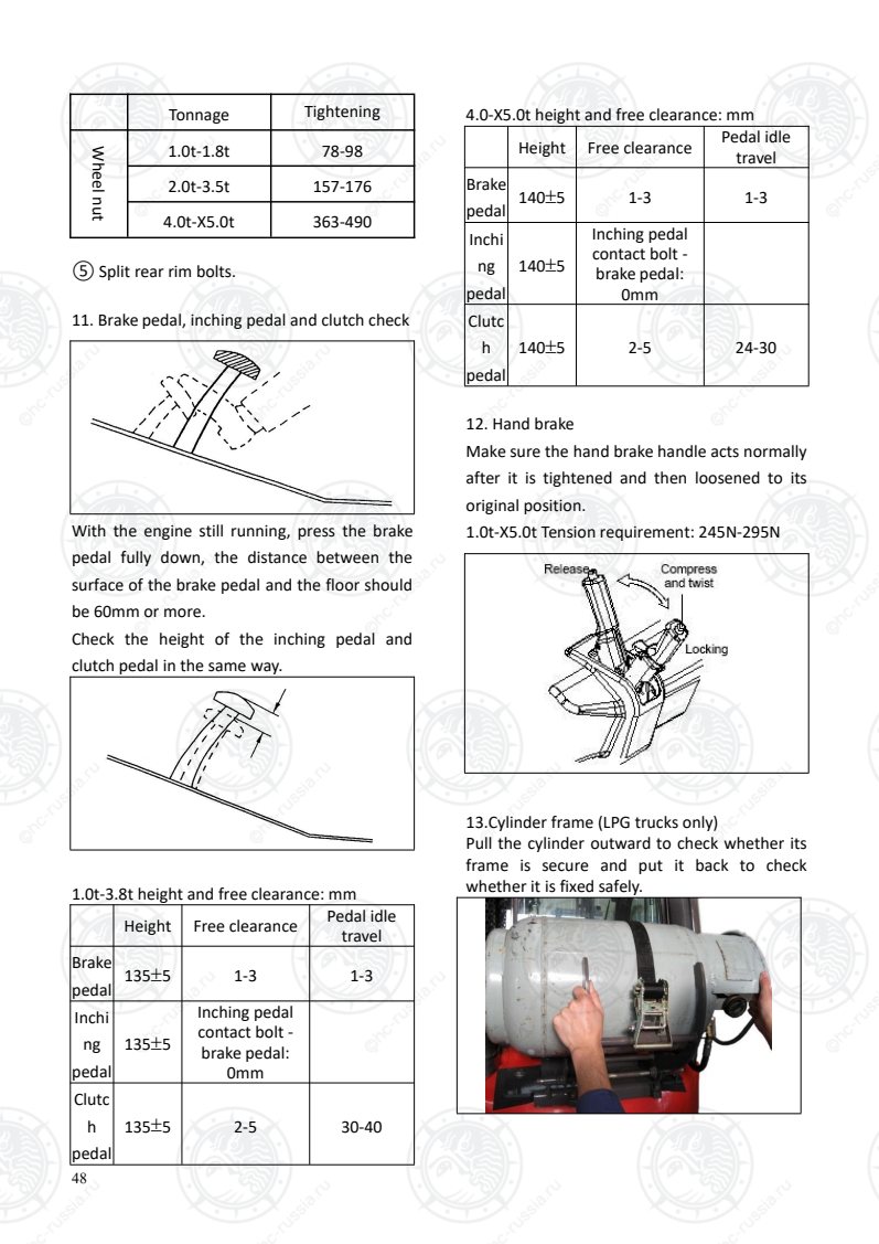
Страница 53
49
3. Every one-and-a-half-month
maintenance (250 hours)
Add the following maintenance items in
addition to the weekly maintenance.
1. Replace the engine oil and oil filter (the first
100h and then every 250 hours thereafter)
① Start the engine, warm it up fully, and then
turn it off.
② Remove the oil filler cap and oil pan drain
plug and drain the engine oil.
Warning
Be careful not to scald yourself as the engine
oil may be hot.
·Emulsified oil indicates that coolant has mixed
with the oil and the cause should be found and
corrected.
·Thin oil indicates that the oil contains gasoline.
③ Wipe clean and install the drain plug and
gasket. Tightening torque of oil drain plug:
29N·m - 39 N·m
④ Remove the oil filter with a suitable tool.
⑤ Wipe the oil filter mounting surface with a
clean cloth.
⑥ Apply a small amount of oil to the rubber
ring of the new oil filter.
⑦ Install the new oil filter by hand only, do
not use a wrench to tighten it.
⑧ Refer to the Forklift Oil List and add the
recommended oil.
⑨ Start the engine and check if there is any oil
leakage in the area around the oil drain plug
and oil filter.
If there is any visible leakage, it indicates that
the part is not properly installed.
⑩ Warm up the engine sufficiently, then shut
it down for a while to check the oil level. Add
more engine oil if necessary.
When checking the oil level, the forklift should
be parked on level ground.
2. Add lubricating grease on the front and rear
pins of the tilt cylinder.
Wipe the filling point clean and then squeeze
out the old oil.
3. Check the gear oil of the drive axle housing
and add more if necessary.
If the working environment is dusty, it is
recommended that after the truck has worked
for the first 200 hours the gear oil in the drive
axle housing is changed.
4. Replace the transmission oil filter (only for
the first time, and then every six months
Оригинальная страница: таблицы и схемы
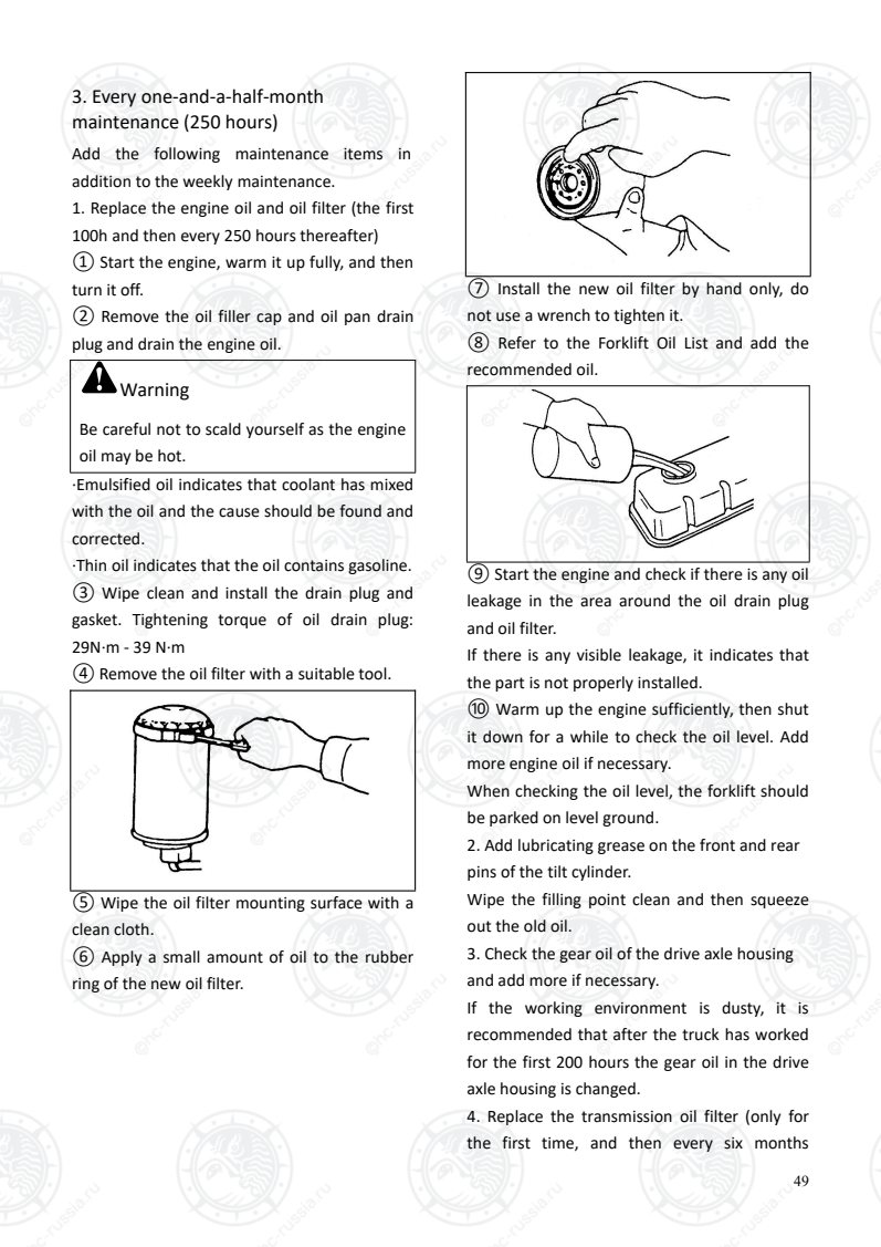
Страница 54
50
thereafter).
Check the condition of the hydrodynamic
transmission fluid, taking into account the
application environment, e.g. if the working
environment is dusty, then the Automatic
Transmission Fluid (ATF) should be changed.
This is only applicable for the initial change.
① Park the forklift truck on a horizontal road,
lower the forks to the ground, tilt the mast
back, pull up the hand brake handle firmly, put
the transmission in neutral and turn off the
engine.
Warning
Hot hydraulic oil, ATF and components may
scald the human body. Do not touch hot
hydraulic oil or associated components.
② Remove the rubber gasket and front base.
③ Remove the filter and dispose of it
according to local regulations.
④ Wipe the filter base and make sure the old
gasket on the base has been removed.
⑤ Apply a small amount of ATF to the new
filter cartridge gasket.
⑥ Fit the filter by hand. When the filter
touches the base, re-tighten it 1/2 to 3/4 turn.
5. Change the hydrodynamic transmission ATF
(only for the first time, and then every six
months afterwards).
Park the forklift truck on a horizontal road,
lower the forks to the ground, pull up the hand
brake handle firmly, put the transmission box in
neutral and turn off the engine.
Warning
Hot hydraulic oil, ATF and components may
scald the human body. Do not touch hot
hydraulic oil or associated components.
① Put a container under the transmission
(with a volume of 20 liters or more).
② Remove the oil drain plug and drain the oil
into the container.
③ Clean the oil drain plug and install it.
④ Take out the oil dipstick, add the ATF (see
the Forklift Oil List) and then replace the
dipstick.
⑤ Start the engine. With the brake pedal
depressed, while the engine is idling, place the
transmission in forward and reverse to prime
the clutch.
⑥ Put the transmission in neutral and pull the
hand brake up.
⑦ Remove the dipstick and observe the fluid
level. If the fluid level is insufficient, add more
ATF to keep the fluid level between the
maximum scale line and the minimum scale
line.
⑧ Check the filter and oil drain plug for any
leakage.
⑨ Turn off the engine and install the front
base.
6. Fuel system exhaust [diesel engines]
Bleed air from the pipelines of the fuel system
in the following cases:
·After running out of fuel and then refuelling.
·After maintenance of the fuel system (e.g.
replacing the fuel filter, draining water from
the fuel filter/oil-water separator or replacing
the fuel system components).
Caution
If the fuel system contains any air, it must be
bled out before the diesel engine is started.
Air bleeding process for trucks with electric
fuel pumps:
① Place a suitable container under the air
outlet.
② Loosen the air outlet by 2 or 3 turns.
③ Rotate the switch to the “ON” position and
hold it for 10-15s until fuel with no bubbles
flows out of the air outlet.
Оригинальная страница: таблицы и схемы
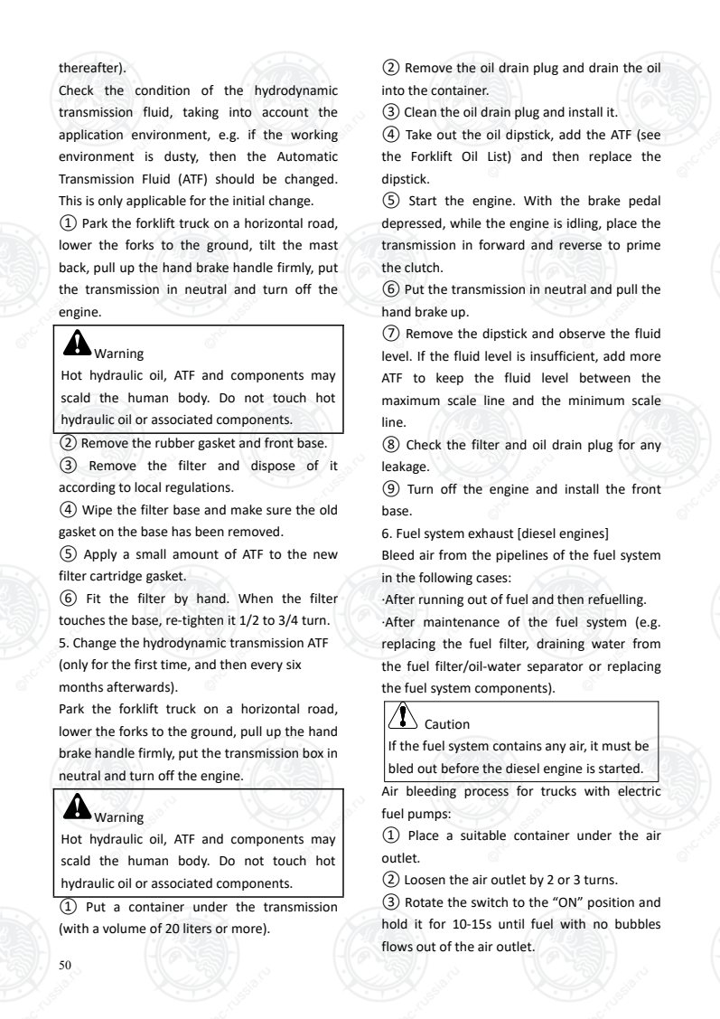
Страница 55
51
④ Tighten the air outlet.
⑤ Clear away the spilled fuel and dispose of it
properly.
⑥ Do not fill the fuel system by turning the
engine with the the starter motor. It may lead
to the starter motor overheating or damage to
the coil, pinion and/or gear ring.
Manual air bleed process:
① Place a suitable container under the air
outlet.
② Loosen the air outlet (1) by 2 or 3 turns.
③ Operate the fuel filling pump (2) until fuel
with no bubbles flows out of the air outlet.
④ Tighten the air outlet.
⑤ Clear away the spilled fuel and dispose of it
properly.
⑥ Do not fill the fuel system by turning the
engine with the the starter motor. It may lead
to the starter motor overheating or damage to
the coil, pinion and/or gear ring.
7. Oil-water separator water drainage [diesel
engines]
Please drain the accumulated water if the fuel
filter alarm light turns on while the engine is
running.
For non-Cummins diesel engines:
① Place a suitable container under the fuel
filter to collect the dirt.
② Loosen the drain plug (2) at the bottom of
the fuel filter. Drain all the water that has
accumulated inside.
③ Tighten the drain plug by hand.
④ After completing these operations, be sure
to fill the diesel system with fuel.
Cummins diesel engine:
Tanked type:
① Turn off the engine;
② Place a container under the fuel filter;
③ Lift the drain valve lever until the fluid is
completely drained from the drain tube and
the fuel is clean;
④ Push up the drain lever until the fluid is
completely drained from the tube.
Оригинальная страница: таблицы и схемы
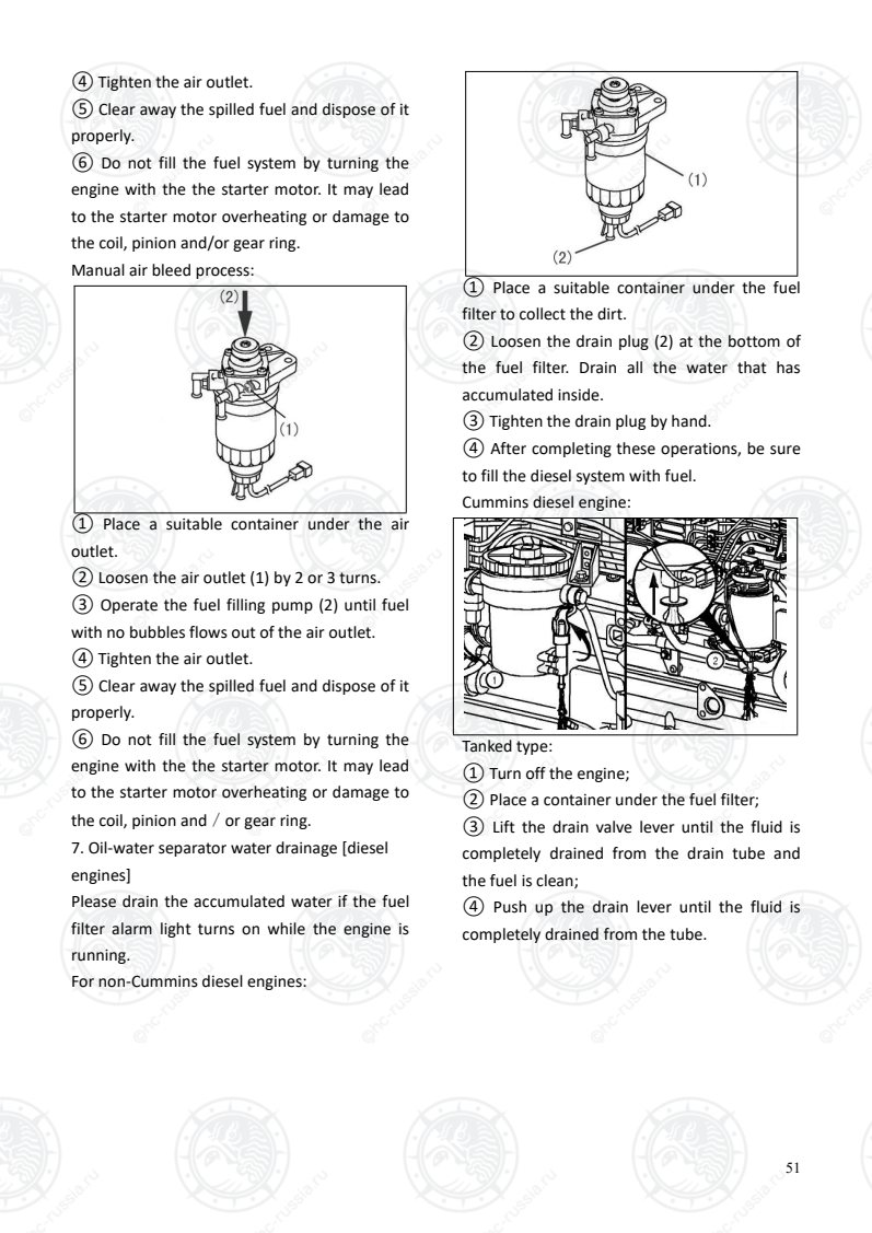
Страница 56
52
Rotating type:
① Turn off the engine;
② Place a container under the fuel filter;
③ Open the drain valve by hand. Rotate the
valve about 3.5 turns counterclockwise until
the valve drops by 25.4mm and starts to drain.
④ Drain the water in the separator until clean
fuel is seen.
Caution
Do not overtighten when closing the drain
valve. Overtightening will damage the threads.
To close the valve, lift the valve and rotate it
clockwise until it is hand tight.
8. Exhaust check
Colorless Complete combustion -
normal
Black Incomplete combustion -
abnormal
Blue Engine oil burning - abnormal
White Water in combustion chamber
- abnormal
Warning
Do not run the engine in places with poor
ventilation because the exhaust contains
carbon monoxide which is poisonous to
humans.
9. Battery and electrolyte inspection
For details, please refer to the procedures for
Using and Maintaining Lead-Acid Batteries.
Оригинальная страница: таблицы и схемы
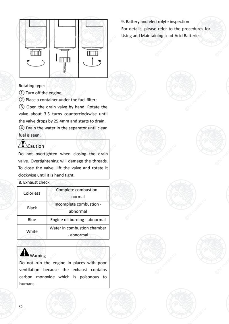
Страница 57
53
4. Semi-annual maintenance (1000
hours)
Add the following maintenance items in
addition to the monthly maintenance.
Add the following maintenance items in
addition to the monthly maintenance.
1. Replacement of brake fluid (1.0t-X5.0t)
① Park the forklift truck on a horizontal road
at the designated maintenance place, lower
the forks to the ground, pull up the hand brake
handle firmly, put the transmission in neutral
and turn off the engine.
② Take off the rubber dust cap on the drain
port, put the two ends of a prepared
transparent hose in the drain port and the
waste oil collection bottle respectively, and
then use a wrench to loosen the drain port
screw counterclockwise while the other person
on the forklift repeatedly presses the brake
pedal. The brake fluid will be sprayed from the
drain port, pay attention to the level of the
brake fluid reservoir, and add new brake fluid
as the fluid level drops. Tighten the drain port
screws after clear brake fluid flows out.
③ Repeatedly press the brake pedal to the
bottom and hold it there while the person
under the forklift loosens the drain port screws,
then tightens the screws after clear brake fluid
comes out and asks the person on the forklift
to release the brake pedal. Repeat the above
operation several times until there are no air
bubbles in the released brake fluid. Pay
attention to the fluid level in the brake fluid
reservoir and add new brake fluid as the level
drops.
Caution
Prevent dust and water from mixing with the
brake fluid when adding it.
Brake fluid is toxic and corrosive and should
be rinsed off if you are exposed to it.
2. Lubrication of the steering wheel locking
device
Apply lubricating grease to the steering
wheel locking device.
3. Check, clean and replace the hydraulic
return oil filter, breathing apparatus and filter
screen
Park the forklift truck on a horizontal road,
lower the forks to the ground, tilt the mast
back, engage the handbrake firmly, put the
transmission box in neutral and turn off the
engine.
① Loosen the bolts on the upper cover
assembly of the hydraulic oil reservoir.
② Remove the return oil filter from the upper
cover.
③ Install the new return oil filter by hand.
④ Remove the filter screen from the oil
reservoir.
⑤ Install a new filter screen by hand.
⑥ Install the upper cover of the oil reservoir
and tighten the bolts.
⑦ Remove the breathing apparatus, clean and
dry it with a clean and non-flammable cleaning
agent and a number of separate air filter
screens.
⑧ Install the breathing apparatus.
⑨ Start the engine and operate the hydraulic
system so that the entire system is primed with
hydraulic oil. Check for leaks.
⑩ Turn off the engine to check the oil level.
Retract all cylinder rods so that the oil level
remains between the scales of the dipstick.
Оригинальная страница: таблицы и схемы
Страница 58
54
4. Check, clean and replace the fuel filter
Caution
In dusty or dirty operating environments, it is
necessary to clean the fuel filter once a
month and replace it every six months.
① Remove the fuel filter assembly.
② Remove the sensor assembly.
③ Install the existing sensor assembly and
apply a little clean fuel to the filter sealing
point before installing a new one.
Caution
Do not refill the filter with fuel before
installation. Otherwise, it will accelerate the
wear of the fuel system components.
④ Install the new filter assembly.
⑤ Turn the new filter until the gasket is
attached to the sealing surface.
⑥ Tighten it by 2/3 turn.
Оригинальная страница: таблицы и схемы
Страница 59
55
5. Annual maintenance (2,000 hours)
Add the following maintenance items in
addition to the semi-annual maintenance.
1. Change hydraulic oil
Park the forklift truck on a horizontal road,
lower the forks to the ground, tilt the mast
back, engage the handbrake firmly, put the
transmission box in neutral and turn off the
engine.
Warning
Hot hydraulic oil, ATF and components may
scald the human body. Do not touch hot
hydraulic oil or associated components.
① Place a container (with a volume over 60
liters) under the hydraulic oil reservoir, remove
the hydraulic oil reservoir drain plug and drain
the hydraulic oil into the container.
② Remove the hydraulic oil dipstick and
hydraulic oil reservoir cover.
③ Take out the magnet in the reservoir to
clean it, and at the same time flush the drain
port at the bottom of the reservoir with
hydraulic oil.
④ Clean and install the oil drain plug.
⑤ Fill the hydraulic oil reservoir. See the
Forklift Oil List. Install the hydraulic oil reservoir
cover and dipstick.
⑥ Start the engine and operate the
multi-valve lever and steering system to fill the
whole system with hydraulic oil.
⑦ Check each hydraulic component and
pipeline for oil leakage.
⑧ Turn off the engine, retract all the cylinder
rods, and check the oil level of the hydraulic oil
reservoir. Add hydraulic oil to the required
scale line.
2. Change the hydrodynamic transmission ATF
See the Change the hydrodynamic transmission
ATF in the Monthly Maintenance Sheet
3. Change the front wheel bearing lubricating
grease
Refer to the content on the drive axle hub in
the Maintenance Manual, disassemble the
wheel bearing, and then change the grease.
4. Change the rear wheel bearing lubricating
grease
Refer to the content on the steering axle in the
Maintenance Manual.
5. Change drive axle gear oil
Park the forklift on horizontal ground. Put it in
neutral and turn off the engine.
① Take off the oil drain plug and drain the oil
into a container. Clean the oil drain plug.
② Install the oil drain plug.
③ Remove the air vent plug and oil level plug.
Add oil into the drive axle housing from the
curved plug seat hole until the oil overflows
from the horizontal plug hole. See the "Refilling
Amount".
④ Install the horizontal plug and curved plug
holder.
⑤ Start the forklift truck. Let the engine idle
and put the direction control handle in the
neutral position.
⑥ Remove the horizontal plug. Maintain the
oil level until the oil overflows.
Оригинальная страница: таблицы и схемы
Страница 60
56
6. Two-yearly maintenance (4,000 hours)
1. Change the engine coolant (every 2-4 years)
① Open the radiator cover and drain plug to
drain the coolant, then flush the cooling
system.
② Tighten the drain plug.
③ Fill the radiator with coolant up to the port.
④ Let the engine run fully.
⑤ Stop the engine, fill the radiator with
coolant up to the port after it has cooled down
completely, then add coolant to the reservoir
up to the Max. level.
⑥ Check if there is any leakage from the drain
plug.
Warning
To avoid the risk of scalding, never change
the coolant when the engine coolant
temperature is higher than 70℃.
The engine coolant added must be an anti-rust
& anti-freeze coolant. Refer to the Forklift Oil
List.
Оригинальная страница: таблицы и схемы
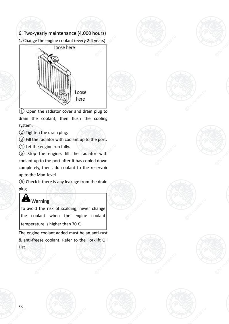
Страница 61
57
7. Others
1.Fuses and relays
① Before replacing any defective fuse or relay,
please find out the cause of failure.
② Replace the fuse with a new one of the
correct specifications.
The forklift control unit is installed on the left
side of the engine inside the internal
combustion engine hood.
2. Tire replacement
Warning
• When using an air compressor, as the
maximum output pressure of the air
compressor is higher than the specified
pressure of the tire, the pressure setting
should be adjusted first; otherwise it may
cause a serious accident.
• In order to ensure safety, the tire should be
placed in a protective frame during inflation.
Front wheel tires
a)Park the forklift on level and solid ground.
b)Start the engine and raise the mast by
approximately 100 mm.
c)Place wooden blocks behind the rear wheels
to prevent the forklift from moving.
d)Loosen each wheel nut 1-2 turns
counterclockwise.
e)Tilt the mast backward and place wooden
blocks at the sides of the outer mast.
f)Tilt the mast forward until the front wheels
are lifted off the ground.
Caution
Do not loosen the nuts until the front wheels
have been lifted off the ground.
g)Place wooden blocks on each front side of
the forklift frame to support the forklift and
then turn off the engine.
h)Remove the wheel nuts and replace the
front wheels.
Caution
a. When removing the tire from the hub, the
rim bolts and nuts should not be removed
until deflating.
b.The wooden blocks should be solid and
strong enough.
c. When the forklift is supported with wooden
blocks only, do not lay under the forklift.
i)Put on the nuts in sequence as shown in the
diagram and lock them temporarily.
j)Start the engine and remove the wooden
blocks from the forklift frame.
k)Tilt the forklift frame backward so that the
forklift is slowly lowered, and then take out the
wooden blocks under the forklift frame and at
the rear wheels.
l)Tighten the tire bolts symmetrically and
crosswise in sequence.
m)Adjust the tire pressure to the specified
value.
Оригинальная страница: таблицы и схемы
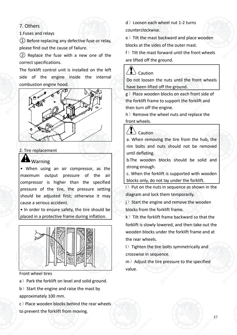
Страница 62
58
Rear wheel tires
a)Park the forklift on level and solid ground.
b)Engage the hand brake and place wooden
blocks behind the front wheels to prevent the
forklift from moving.
c)Place the jack at the bottom cut of the
counterweight as shown in the diagram.
Note: Make sure the minimum bearing weight
of the jack is 2/3 of the total weight of the
forklift truck.
d)Loosen the nuts on the wheel 1-2 turns
counterclockwise.
Warning
Do not remove the nuts until the rear
wheels are lifted off the ground.
e) Slowly lift the forklift with a jack until the
rear wheels are completely off the ground.
Place wooden blocks on each rear side of the
forklift frame to support the forklift as shown
in the diagram.
f)Remove the wheel nuts and replace the rear
tires.
Warning
a. When removing the tire from the hub, the
rim bolts and nuts should not be removed
until deflating.
b. Make sure that the wooden blocks used to
support the forklift are solid and strong
enough.
c. When the forklift is supported with
wooden blocks only, do not lay under the
forklift.
g)Put on the nuts in sequence as shown in the
diagram and lock them temporarily.
h)Remove the wooden blocks under the frame,
lower the forklift slowly to the ground and
remove the wooden blocks and jack behind
the front wheels.
i)Tighten the nuts to the specified torque in a
crosswise manner. Please refer to the
Tightening Torque Table.
j)Adjust the tire pressure to meet the specified
parameters.
Оригинальная страница: таблицы и схемы
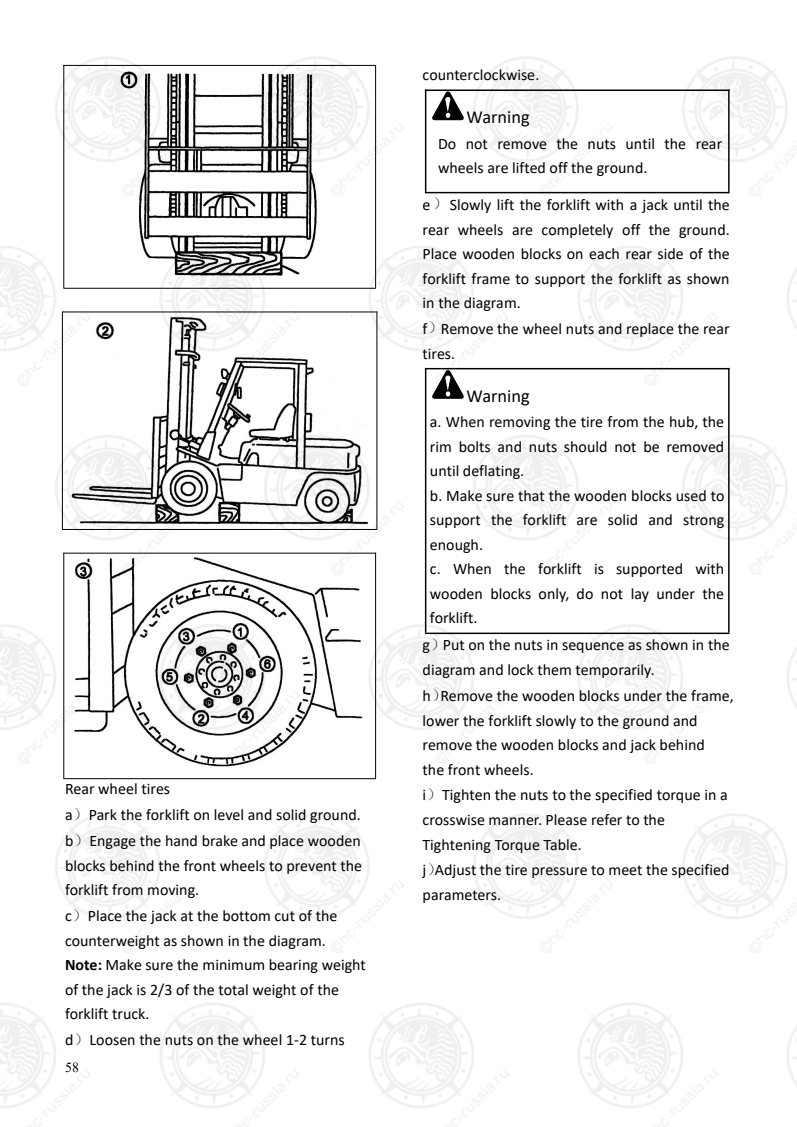
Страница 63
59
3. Preparation for hot/cold conditions
Select oil with an appropriate viscosity for the
ambient temperature.
4. Clean the radiator fins
Warning
Airborne dust may get into your eyes, so
protective glasses or dust goggles should be
used.
If the radiator fins are blocked, it will cause
overheating, so compressed air, steam or
water should be used to blow the fins.
Caution
When using compressed air or steam to
clean the radiator fins, place the nozzle at a
right angle to the radiator.
5. Operations for an overheated engine
If the engine is overheated, do not stop the
engine immediately, the following steps should
be taken:
①Run the engine at low speed.
②Open the hood to improve the ventilation of
the engine bay.
③Stop the engine when the water
temperature decreases.
④Check the coolant and add water if
necessary.
6. DPF ash removal
The longer the DPF is run, the more ash
(combustion residue) will be collected in the
filter. Excessive ash accumulation can adversely
affect DPF performance.
If there is an alarm or every 4,000 working
hours (every 2,000-3,000 hours for Yuchai
engines), it is necessary to contact the
after-sales service to clean the DPF with a
professional ash cleaning device.
For any queries, please contact the sales
company or agent of HANGCHA GROUP CO.,
LTD.
Оригинальная страница: таблицы и схемы
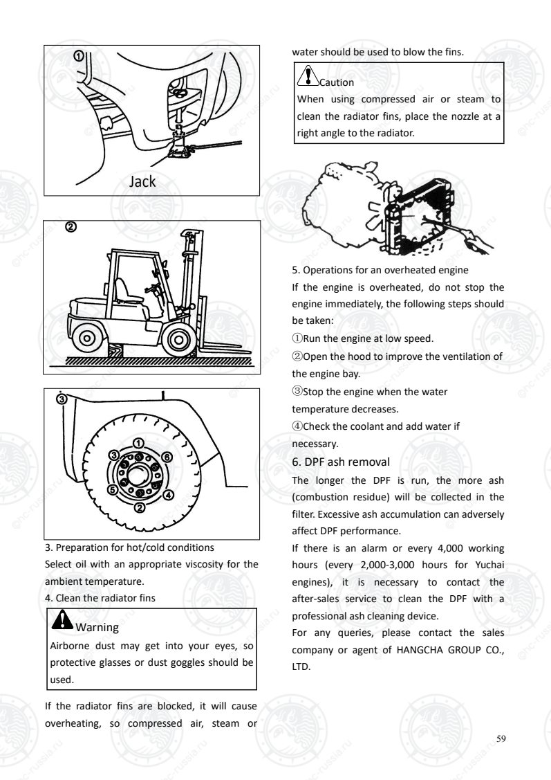
Страница 64
60
V. Forklift truck structure and stability
Be aware that the structure and stability of the forklift truck are very important to safe operation.
Caution
Forklift truck structure
The basic components of the forklift truck are the lifting device
(forks and mast) and the forklift truck itself at the rear (with tires).
The front wheels of the forklift truck can be used as a fulcrum to
keep balance between the center of gravity of the forklift truck and
that of the load.
The relationship between the center of gravity of the forklift truck
and that of the load is critical to the operation of the forklift truck.
Cautio
n
Center of gravity of load
The load profiles handled with the forklift truck vary; in
order to evaluate the forklift truck and stability, it is very
important to identify the center of gravity for loads in
different shapes from boxes to boards and rectangular
objects.
Warning
Do not jump out of the truck if the forklift truck starts to roll over. The forklift truck will roll over
much faster than you can jump out of the truck; you should extend your feet and keep your hands
on the steering wheel firmly to hold you in
the cab.
Please fasten the safety belt securely. WARNING Faste Seatblet Do Not Jump! Brace
Feet
Hold
 on
Tight
 Lean Away
 From Impact
Truck can
TIP OVER!
Risk of serious
INHURY
 or DEATH!
Оригинальная страница: таблицы и схемы
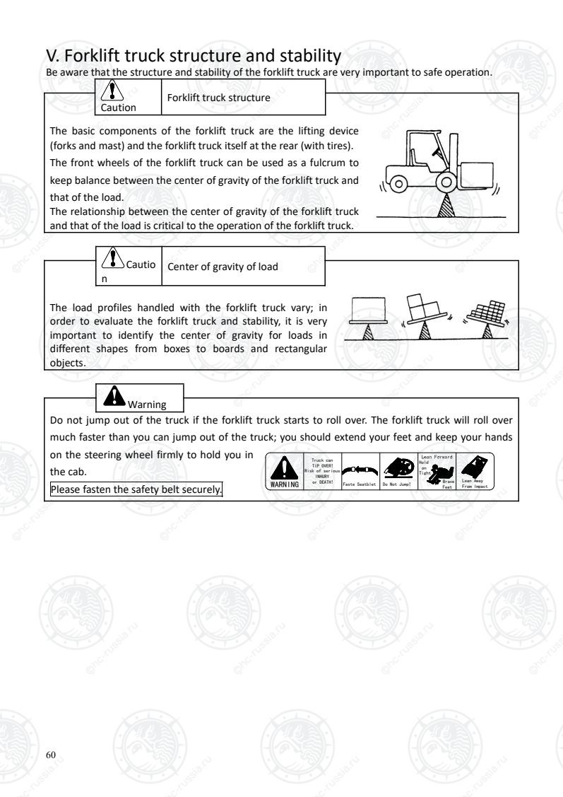
Страница 65
61
Caution
Center of gravity and stability
The center of gravity of the forklift truck depends on the combined center of gravity of the forklift
truck.
When the forklift truck is unloaded, the center of gravity remains unchanged; when it is loaded, the
center of gravity is formed by the combined center of gravity of the forklift truck and the load.
The center of gravity of the load is determined by
whether the mast is tilted forward or backward or
whether it is lifted or lowered, thus the combined center
of gravity can change.
The combined center of gravity of the forklift truck is
determined by the following factors:
· Load magnitude, weight and shape;
· Lift height;
· Tilt angle of the mast;
· Tire inflation pressure;
· Acceleration, deceleration and turning radius;
· Road conditions and road tilt angle;
· Accessory type.
Cautio
n
Stable center of gravity region
In order to make the forklift truck stable, the combined
center of gravity has to be within the triangle formed by
contact point of the front left and right tires and the
midpoint of the rear axle.
If the combined center of gravity is on the rear axle, the two
front tires will form a fulcrum and the forklift truck will tilt
forward. If the combined center of gravity moves out of the stable center of gravity triangle, the
forklift truck will roll over in the direction towards the combined center of gravity.
Caution
Maximum load (weight and load
center distance)
The horizontal distance between the center of gravity of the load
on a fork and the load-backrest of the fork or the front surface of
the fork (whichever is smaller) is called the load center distance.
The maximum load refers to the maximum load that the fork can
bear at the standard load center distance. The relationship
between the maximum load and the load center distance is
shown on the Bearing Capacity Chart of the forklift truck. If the load center distance moves towards
the front fork, the overall center of gravity will move forward, thus the load has to be reduced.
Оригинальная страница: таблицы и схемы
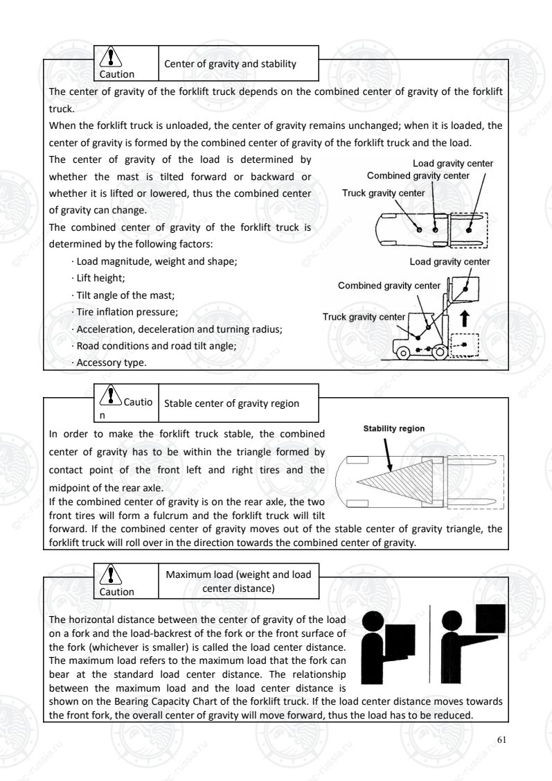
Страница 66
62
Caution
Bearing Capacity Chart
The chart shows the relationship between the
location of the load center distance and the
maximum load. Check whether the load and the
load center distance are within the allowable range
of the Bearing Capacity Chart before loading. If the
load shape is complicated, the heaviest part should
be placed in the center of the fork and close to the
load-backrest.
Caution
Speed and acceleration
A static object should remain static without an external force. Similarly, a moving object continues to
move at the same speed without an external force, which is referred to as inertia.
Due to inertia, when the forklift truck starts to move forward, a force acts backwards; when the
truck stops, a force acts forward. It is dangerous to suddenly apply the brake, because the forklift
truck will roll over or the load will slide when a large force acts forward.
When the forklift truck turns, a centrifugal force will be applied outwards from the turning center.
The forklift truck can be pulled out and rolled over by the force. The left and right stability regions
are small; thus, the forklift truck should slow down to avoid rolling over when turning. If the forklift
truck carries a high load and the overall center of gravity is high, the forklift truck may easily tilt
forward, to the left or to the right.
Оригинальная страница: таблицы и схемы
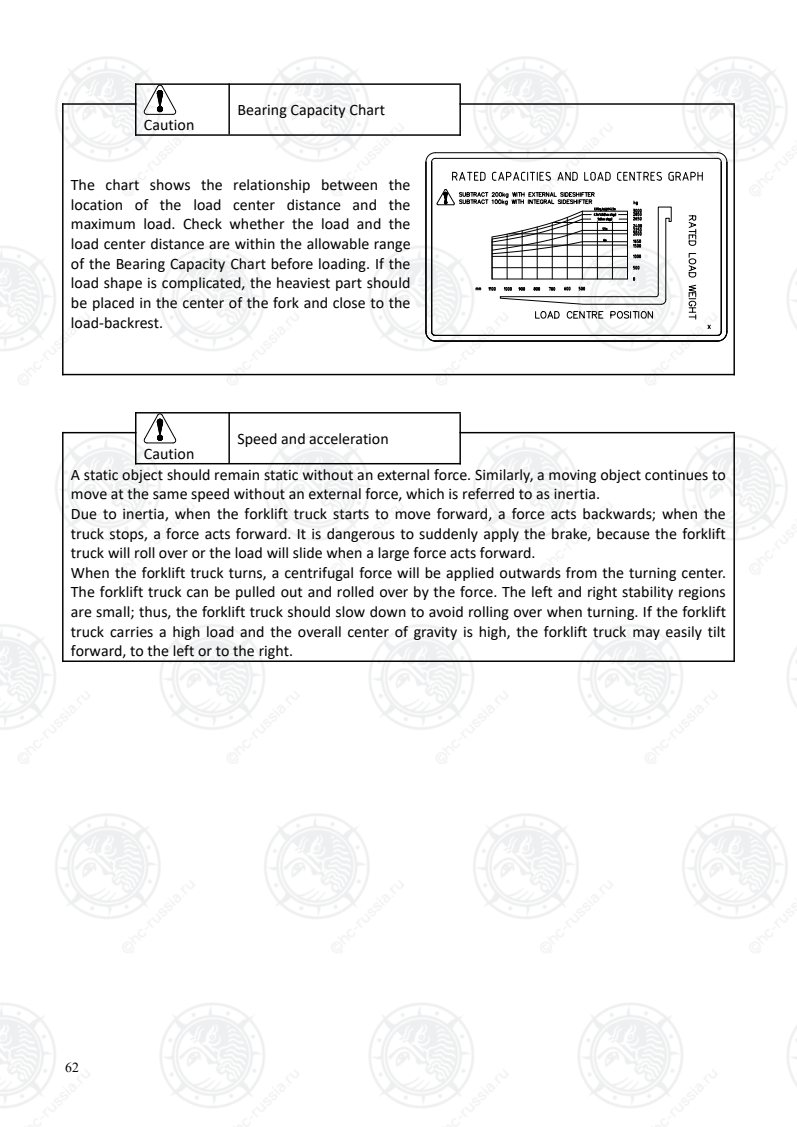
Страница 67
63
VI. Operation
Warning
If the forklift truck has any damage or faults,
it should not be started before repairing.
1. Start
Starting the diesel forklift truck
① Pull the shift lever in the neutral position.
②Start after rotating the starting switch to
“ ” position, and then put the key back to
“┃”.
Caution
·If the truck fails to start within 5s, the
starting switch should be rotated to “O” and
the truck should be restarted after an
interval of 2 min.
·If the truck fails to start three consecutive
times, the cause should be investigated.
Caution
·When the ambient temperature is lower
than -5℃ , the key should be rotated to the
right in the “┃” position for preheating; after
the preheat indicator light turns off, the key
can be rotated to “ ” for starting.
Starting gasoline forklift trucks
① Engage the gear shift lever in the neutral
position.
② Cool the engine down.
Open the choke knob fully, depress the
accelerator pedal 2-3 times and release it,
rotate the key switch to the “START” position to
start the engine and then release it.
③ Warm up the engine.
Do not open the choke knob, depress the
accelerator pedal halfway and hold it, rotate the
key switch to the “START” position to start the
engine and then release it.
Caution
Do not depress the accelerator pedal to the
bottom when starting a hot engine as it may
cause failure to start. The engine will not
start easily even if the accelerator pedal is
depressed several times.
Caution
The starting time should not exceed 5s and
the intervals between starting attempts
should not be less than 2min.
After the engine is started
① Preheat the engine for about 5min.
② Check the operating conditions of the
engine.
Caution
Diesel engine
Depress the accelerator to make it run at an
intermediate speed (1,800r/min -
2,000r/min) after the diesel engine is started
to preheat the engine without load.
Gasoline engines
After the gasoline engine is started, gradually
push the choke forward, observe the warm
up condition and the stability of the gasoline
engine speed, and then push the choke fully
forward after confirming that the engine has
warmed up.
· Check the compression (no ignition) sound.
· Check exhaust conditions.
· Confirm that all indicator lights have turned
off.
· Operate the multi-way valve control lever
2-3 times throughout the process and check
the operations of the mast after the engine is
fully warmed up.
Оригинальная страница: таблицы и схемы
Страница 68
64
2. Operation
○1 Hold the steering wheel lever with your left
hand. Put your right hand on the steering wheel
gently to get ready for loading/unloading
operations.
○2 When the distance between the fork bottom
and the ground is 15cm-20cm, the mast will tilt
backwards in place.
○3 Look around the forklift truck to see if there
are any pedestrians and sound the horn.
Manual transmission forklift trucks
·Depress the clutch pedal and operate the gear
shift lever.
·Release the hand brake.
·Depress the accelerator pedal and slowly
release the clutch pedal at the same time to
drive the truck.
Caution
Do not step on the clutch pedal when driving
the truck.
Hydraulic drive forklift trucks
·Step on the brake pedal and operate the
front/rear changeover switch.
·Release the hand brake.
· When the brake pedal is released and the
accelerator pedal is depressed, the truck will
start moving.
Gear shift
Manual transmission forklift trucks
·Stop the truck before shifting gear.
·Depress the clutch pedal, and toggle the shift
lever, release the clutch pedal and then depress
the accelerator pedal.
Hydraulic drive forklift trucks
·Stop the truck before shifting gear.
·Toggle the shift lever.
Slowing down
Manual transmission forklift trucks
The mechanical transmission is equipped with a
synchronizer, release the accelerator pedal,
depress the clutch pedal to the bottom, place
the shift lever in Gear I, release the clutch pedal
and then depress the accelerator pedal.
Hydraulic drive forklift trucks
Slightly release the accelerator pedal, and step
on the brake pedal, if necessary.
Steering
The forklift truck is different from ordinary
vehicles, because its rear wheels are used for
steering; the rear counterweight is rotated
outwards at the time of steering.
Slow down and rotate the steering wheel
towards the side to turn; the steering wheel
needs to be rotated a little bit earlier than front
steered vehicles.
Parking
① Slow down, step on the brake pedal to stop
the truck (on manual transmission forklift trucks,
step on the clutch at the same time).
② Place the shift lever in the neutral position.
③ Pull up the hand brake.
④ Lower the forks to the ground and tilt the
mast forward to the maximum extent.
⑤ Shut down the engine when the
ignition key switch is in the “O” position;
pull out the engine shutdown lever from
the diesel forklift truck, take out the key
and keep it safe.
Caution
·Be careful when getting off the truck and do
not jump out.
·The truck should not stop on the driving route.
Оригинальная страница: таблицы и схемы
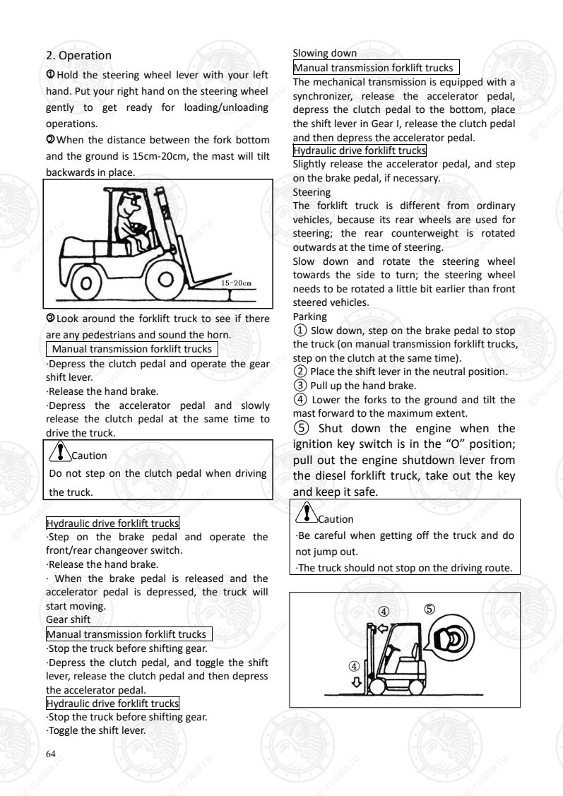
Страница 69
65
3. Loading
·Adjust the fork spacing to keep cargo balanced.
·The truck should be facing the cargo when
loading.
·The pallets should be symmetrically placed on
the two forks.
·The forks should be inserted into the pallets.
·Lifting cargo:
○1 First lift the forks 5cm-10cm above the ground
to confirm whether the cargo is secure.
○2 Then, tilt the mast backwards, lift the cargo
5cm-10cm above the ground, and start to drive.
· Please drive in reverse when handling large
cargo that obstructs visibility, except when
climbing ramps.
4. Stacking
·Slow down when approaching the place to
store the cargo.
·Park the truck in front of the place to store the
cargo.
·Check the place to store the cargo.
·Tilt the mast forward to the fork level and lift
the forks to a position slightly higher than the
unloading site.
·Move forward, put the cargo on the unloading
site and stop.
·Slowly lower the forks after confirming that the
cargo is above the unloading site and confirm
that the cargo is safe and in place.
·Conduct necessary lifting and tilting operations,
move the forklift truck back and take the forks
out from the cargo.
·Lower forks to 15cm-20cm above the ground
after fork tips are clear from the cargo.
·Tilt the mast backwards.
Warning
·Do not tilt the mast when the load is lifted
above 2m.
·Do not get off the truck or leave the truck
when the load is at a high level.
5. Unstacking
·Slow down when the forklift truck approaches
the place to pick up the cargo.
·Park when the forklift truck is 30cm away from
the cargo.
· Check the cargo condition.
·Tilt the mast forward to the fork level and lift
the forks to the position of the pallet or crosstie.
·Confirm whether the forks are aligned with the
pallets, move forward slowly, try to insert forks
into the pallets and stop.
Caution
·If it is difficult to insert forks fully into the
pallets, the truck can move forward to insert
the forks 3/4 of the way into the pallets. Lift
the forks 5cm-10cm, move the truck
backwards 10cm-20cm, lower the pallets or
crossties, and move the truck forward to fully
insert the forks into the pallets or crossties.
Оригинальная страница: таблицы и схемы
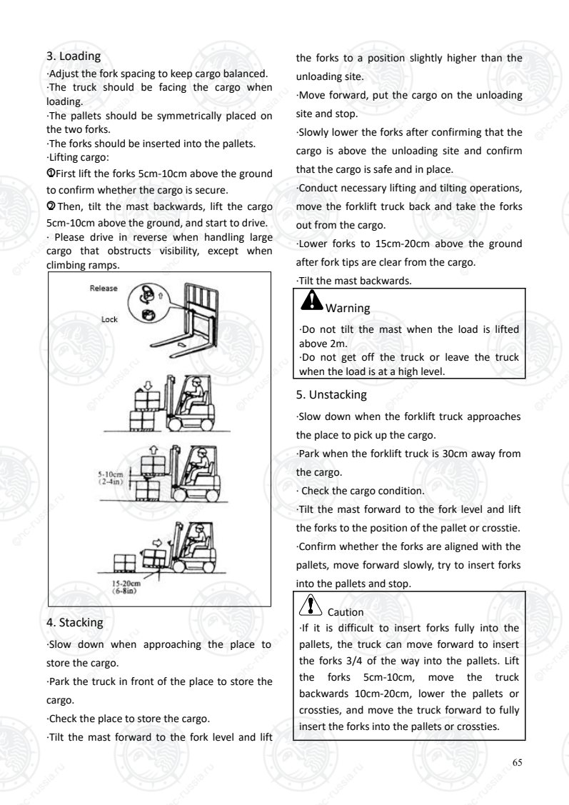
Страница 70
66
·Lift the forks 5cm-10cm above the stacking
place.
·Look around the truck, confirm whether there
are any obstacles, and move backwards slowly.
·Lower the forks to 15cm-20cm above the
ground, tilt the mast backwards, and transport
the cargo to the destination.
Оригинальная страница: таблицы и схемы
Страница 71
67
VII. Storage
1. Daily storage
a)Park the forklift at the designated place and
use wedge blocks to support the wheels.
b)Place the shift lever in the neutral position.
c)Pull up the hand brake handle.
d)Turn off the engine and operate the
multi-valve handle several times to release the
remaining pressure in the oil cylinder and
pipeline.
e)Remove the key and keep it in a safe place.
Warning
Once a forklift is found to be defective, it
should be reported to the management and
repaired immediately.
Then the following maintenance items should be
carried out.
a)Remove oil and grease from the vehicle body
with a cloth and water.
b)Check the overall condition of the vehicle, in
particular check whether the tires are damaged
or have any foreign objects such as nails.
c)Fill the fuel tank with specified fuel.
d)Check for leaks of hydraulic fluid, engine oil,
fuel or coolant.
e)Apply lubricating grease.
f)Check whether the mating surface of the
wheel nut and cylinder piston rod is loose and
whether the surface of the piston rod is
scratched.
g)Check whether the mast rollers act smoothly.
h)Raise the lifting cylinder to the top to fill the
cylinder with oil.
i)In winter or cold environments, long-lasting
antifreeze does not need to be drained, but if
cooling water is used, the reservoir should be
emptied.
2. Long-term storage
When the forklift is parked for a long time, use
wooden blocks to support the vehicle body and
counterweight to reduce the loading on the rear
wheels.
Warning
a. The wooden block must be solid and
should be strong enough to support the
weight of the forklift truck.
b. Do not use blocks higher than 300 mm
(11.81 inches).
c. Raise the forklift just enough to place it
on the supporting blocks.
d. Place blocks of the same size under the
left and right sides of the forklift frame.
e. After supporting the forklift with the
blocks, push the forklift back and forth &
left and right to check whether it is stable.
Carry out the following maintenance and checks
in addition to maintenance as required in Daily
Storage.
a)Remove the battery from the forklift, put it in
a dry and cool place, and charge it once a
month.
b)Apply anti-rust oil to exposed parts such as
the piston rod and shaft that may rust.
c)Parts such as vent plugs and air filters should
be covered to prevent water ingress.
d)Start the forklift truck once a week. If the
cooling water was drained out, it should be
refilled. Install the battery. Remove the anti-rust
oil on the piston rod and shaft, start the engine
and warm up fully, run slowly back and forth,
operate the mast to raise and lower, and tilt
back and forth several times.
Оригинальная страница: таблицы и схемы
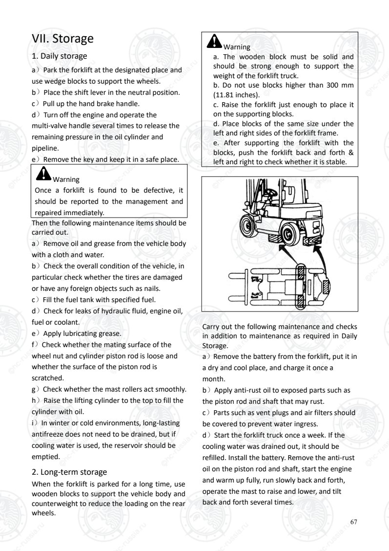
Страница 72
68
e)Forklift trucks should not be parked on
asphalt roads in summer.
3. Operation of forklift trucks after
long-term storage
a)Remove the anti-rust oil from the exposed
parts.
b)Drain the oil from the engine crankcase, drain
the gear oil or ATF in the drive axle housing and
hydrodynamic transmission (only for
hydrodynamic transmission forklift trucks), clean
the interior and add new oil.
c)Clear away the foreign matter and water in
the hydraulic oil tank and fuel tank.
d)Remove the engine cylinder head, valve and
rocker arm shaft, and check whether each valve
clearance is normal.
e)Add coolant to the specified scale line.
f)Charge the battery, mount it on the forklift
and connect the battery leads.
g)Carefully carry out the pre-start inspection to
check the starting, forward, reverse, steering,
lifting, lowering, front and rear tilting functions
of the forklift truck.
h)Preheat the forklift truck.
Оригинальная страница: таблицы и схемы
Страница 73
69
VIII. Maintenance
Note:
a)Do not repair forklifts without training.
b)It is necessary to perform regular checks and maintenance to keep the performance of the truck at
optimum.
c)When operating in dusty or polluted environments, it is necessary to increase the frequency of
maintenance.
d)Checks and maintenance are often neglected, so it is better to find the problems early and solve
them in time.
e)When changing or adding oil, do not use oil which is not the same as the original.
f)If the engine power drops, there is any black smoke or the engine noise becomes louder before
maintenance is due, inspections and checks should be carried out and the opening pressure of the
diesel nozzle and fuel atomization state should be adjusted if necessary.
g)The used oil/fluid and used battery should be recycled according to the local environmental
protection laws and regulations to prevent pollution of the environment, rather than poured away or
disposed of at will.
h)Develop a comprehensive maintenance and repair plan.
i)Complete records should be made after each maintenance and repair.
j)Use the spare parts from Hangcha.
1. Regular maintenance schedule
○——Check, correction, adjustment
×——Replacement
Note:
(1) When operating in dusty or polluted environments, it is necessary to increase the frequency of
maintenance. The tips on maintenance dates from the intelligent module are only for reference.
Please see this Manual for the maintenance cycle and items.
(2) If the engine power drops, there is any black smoke or engine noise becomes louder before the
maintenance period arrives, inspections and checks should be carried out and the opening pressure of
the diesel nozzle and fuel atomization state should be adjusted if necessary.
(3) Replace the engine lubricating oil at the first 100h and then every 250 hours thereafter. For
common-rail engines, the maintenance cycle may be appropriately shortened. (For details, please
refer to the Engine Maintenance Manual).
Оригинальная страница: таблицы и схемы
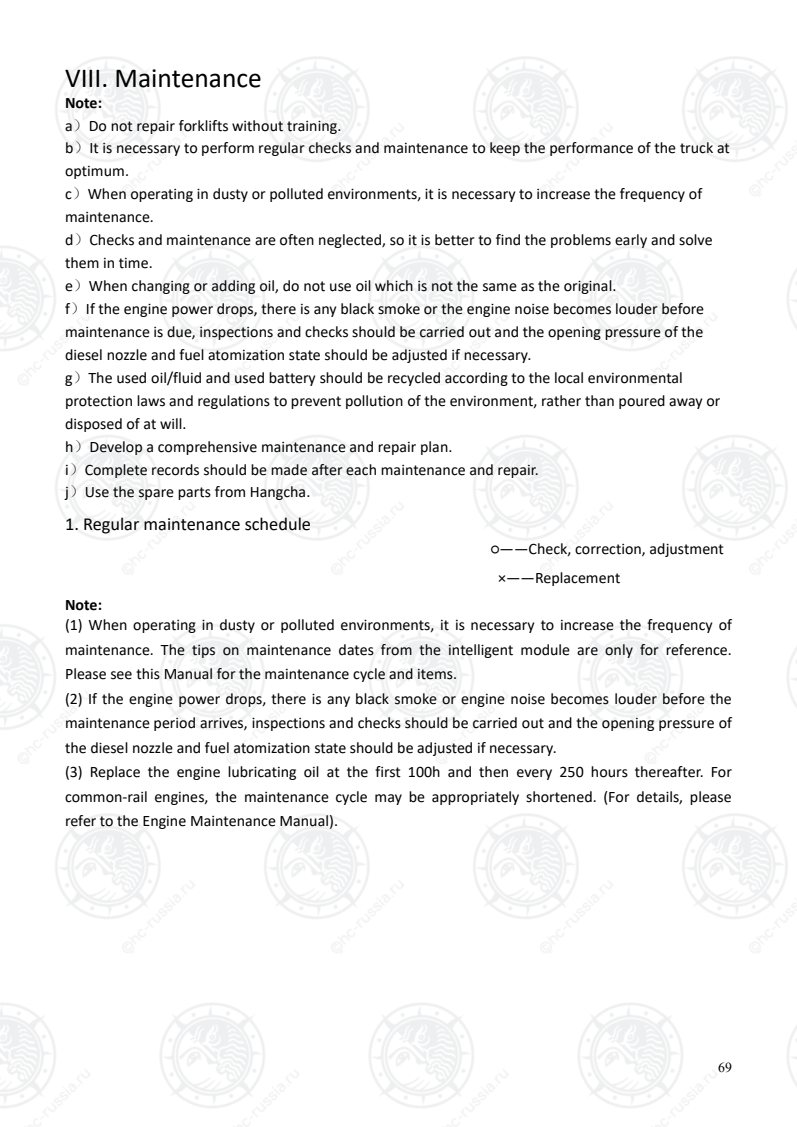
Страница 74
70
Engine Regular Maintenance Schedule
Mainten
ance
Item
Maintenance Content Tool Daily
(8h)
Every month
and a half
(250h)
Trimonthly
(500h)
Semi-annua
lly
(1,000h)
Annually
(2,000h)
Engine
.
.
Visual inspection of the
engine running
condition (including
sound, exhaust color)
○ ○ ○ ○ ○
Clean or replace the air
filter cartridge (Blow the
outer filter cartridge
and pat the inner filter
cartridge, i.e. safety
filter cartridge)
○ ○ ○ × ×
Oil-water separator
water drainage (Diesel
engines)
○ ○ ○ ○ ○
Check crankcase and
remove dirt ○ ○ ○
Check and adjust valve
clearance
Plug
gauge
First time
○ ○ ○ ○
Tighten the cylinder
cover bolts
Torque
wrench
First time
○ ○ ○ ○
Ignition plug (gasoline
engine) ○ ○ ○ ○
Check the distributor
block contact, lid and
rotor (gasoline engine)
(1)
○ ○ ○ ○
Check the distributor
block interior (IC
ignition system) (1)
○
Commo
n-rail
engine
Check whether the rail
pressure sensor and its
line operation is normal
○ ○ ○ ○ ○
Check whether the
accelerator pedal is
normal.
○ ○ ○ ○ ○
Check the functions of
the rail pressure relief
valve and check for
leaks
○ ○ ○ ○ ○
Check the ECU function
and wiring ○ ○ ○ ○ ○
Check the camshaft
sensor and its line ○ ○ ○
Check the crankshaft
sensor and its line ○ ○ ○
Fill with specified fuel ○ ○ ○ ○ ○
Оригинальная страница: таблицы и схемы
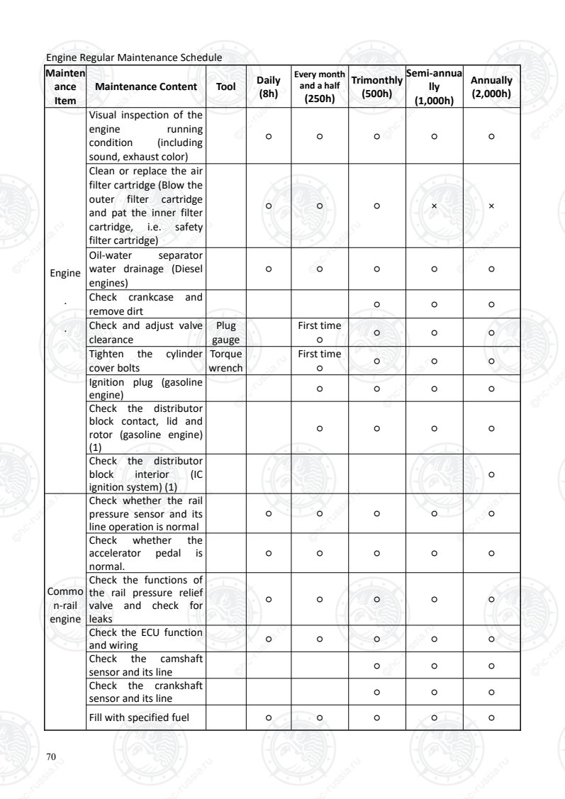
Страница 75
71
Mainten
ance
Item
Maintenance Content Tool Daily
(8h)
Every month
and a half
(250h)
Trimonthly
(500h)
Semi-annua
lly
(1,000h)
Annually
(2,000h)
DPF Cleaning Clean the DPF in case of an alarm or every 4000 working
hours.
Mainten
ance
Item
Maintenance Content Tool Daily
(8h)
Every month
and a half
(250h)
Trimonthly
(500h)
Semi-annua
lly
(1,000h)
Annually
(2,000h)
L
P
G
Engine
.
.
1. Check the LPG
pipelines and the joints
for any leakage (1)
○ ○ ○ ○ ○
2. Drain the tar from
the pressure reducing
regulator
○ ○ ○ ○ ○
3. Check the pipelines
and the joints for any
damage
○ ○ ○ ○ ○
4. Check the LPG tank
mounting bracket for
any looseness or
damage
○ ○ ○ ○ ○
5. LPG Filter ○ ○ ×
Cranksh
aft
ventilat
or
Check for clogged or
damaged PCV valves
and tubes
○ ○
Speed
controller
or
injection
pump
Check maximum speed
while unloaded
Tachom
eter ○
Lubricat
ion
.
System
.
Check the engine for
leaks ○ ○ ○ ○ ○
Check the oil level and
cleanliness ○ ○ ○ ○ ○
Change the engine oil
(1)
×
First time
(100h)
× × ×
Change the engine oil filter
cartridge (1)
×
First time
(100h)
× × ×
Fuel
.
System
.
Visual inspection of oil
pipes, oil pumps and oil
tanks for leaks
○ ○ ○ ○ ○
Replace the fuel filter × × × ×
Check the nozzle and
adjust the pressure
state (diesel engine) (2)
Fuel
injection
testbed
○ ○ ○
Ignition timing
(gasoline engine) ○ ○ ○ ○
Оригинальная страница: таблицы и схемы
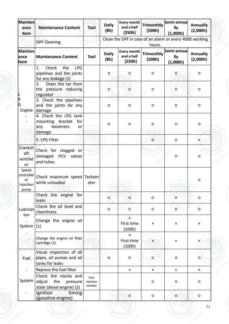
Страница 76
72
Mainten
ance
Item
Maintenance Content Tool Daily
(8h)
Every month
and a half
(250h)
Trimonthly
(500h)
Semi-annua
lly
(1,000h)
Annually
(2,000h)
Injection time ( diesel
engine) ○
Water drainage of fuel
tank ○ ○ ○
Clean the fuel tank ○ ○
Check the fuel amount ○ ○ ○ ○ ○
Cooling
.
System
.
Coolant amount ○ ○ ○ ○ ○
Check for any leakage ○ ○ ○ ○ ○
Change the engine
coolant
×
(2-4) years
Check the fan belt
tension and check for
any damage
○ ○ ○ ○ ○
Clean the water tank
outer surface
Monthly in
summer ○ ○ ○
Performance and
mounting condition of
water tank cover
○ ○ ○ ○
Condition of the
inlet/outlet tube ○ ○
Regular Maintenance Schedule for Transmission System
Maint
enanc
e
Item
Maintenance Content Tool Daily
(8h)
Every month
and a half
(250h)
Trimonthly
(500h)
Semi-annua
lly
(1,000h)
Annually
(2,000h)
Clutch
Check and adjust the
height and free
clearance of the clutch
pedal
○ ○ ○ ○
Check the clutch
release bearing
lubrication
○ ○ ○
Manu
al
trans
missio
n
Check the oil level and
replace it if necessary ○ ○ ○ ×
Hydra
ulic
.
trans
missio
Clean the coarse filter
screen ○ First time ○ ○
Replace the oil filter × ×
Check for any leakage ○ ○ ○ ○ ○
Check the oil amount
or change it
×
First time ○ ○ ×
Оригинальная страница: таблицы и схемы
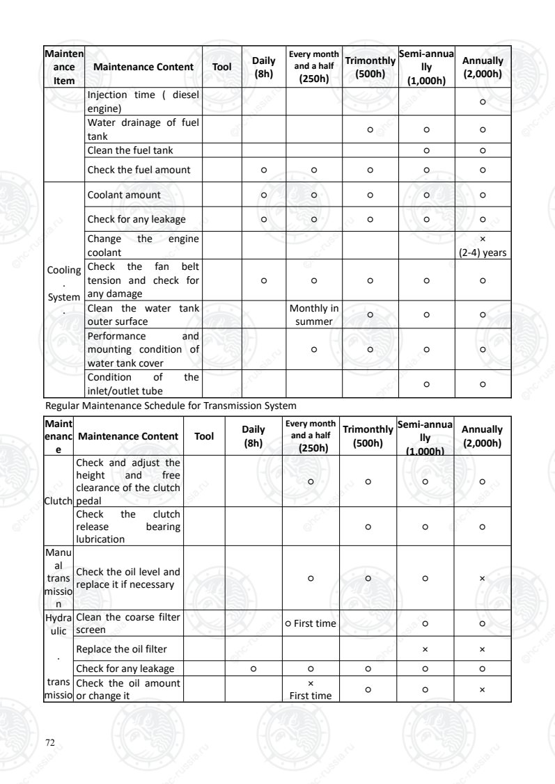
Страница 77
73
Maint
enanc
e
Item
Maintenance Content Tool Daily
(8h)
Every month
and a half
(250h)
Trimonthly
(500h)
Semi-annua
lly
(1,000h)
Annually
(2,000h)
n
.
.
Idle running state of
inching pedal
.
○ ○ ○ ○ ○
Performance of
control valve and
hydrodynamic
clutch
○ ○ ○ ○ ○
Performance of
inching valve ○ ○ ○ ○ ○
Operation and
looseness of the shift
lever
.
○ ○ ○ ○
Driveaxle(frontaxle)
Check the hub bearing
for looseness and
noise
.
○ ○ ○ ○
Clean and refill
lubricating oil × ×
Check for leakage ○ ○ ○ ○ ○
Check the axle body
for any deformation,
cracks
or damage
○ ○ ○
Check the tightness of
the bolts in the joints
of the vehicle frame
.
○ ○ ○
Check the tightening
torque of the hub nuts
.
Torque
wrench ○ ○ ○ ○ ○
Regular Maintenance Schedule for Wheels (Front/Rear)
Maint
enanc
e
Maintenance Content Tool Daily
(8h)
Every month
and a half
(250h)
Trimonthly
(500h)
Semi-annua
lly
(1,000h)
Annually
(2,000h)
Tires
.
Inflation pressure Pressure
gauge ○ ○ ○ ○ ○
Wear, cracks or
damage ○ ○ ○ ○ ○
Check the tires for any
nails,
stones or other foreign
matter
○ ○ ○ ○
Check the rim for any
damage ○ ○ ○ ○ ○
Looseness of split rim
bolts
.
Inspecti
on
hammer
○ ○ ○ ○ ○
Оригинальная страница: таблицы и схемы
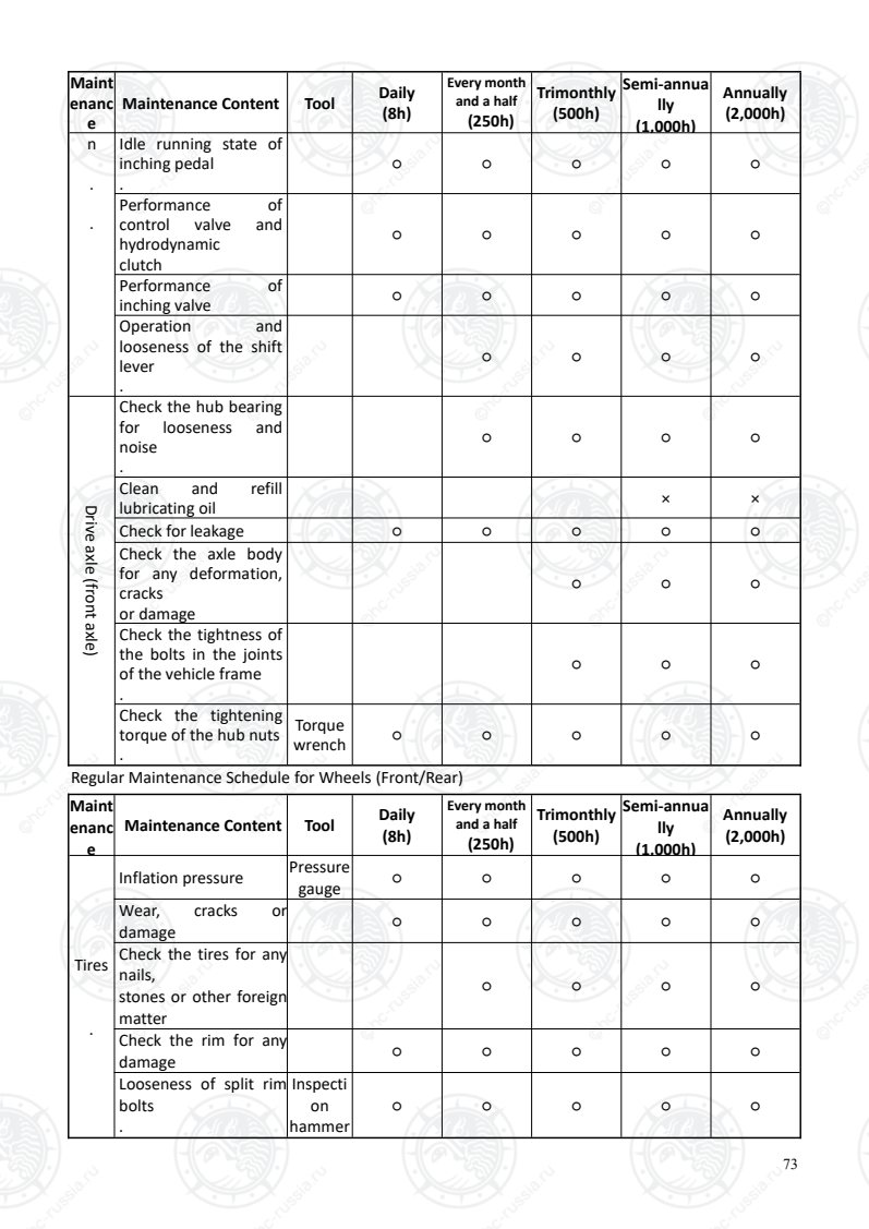
Страница 78
74
Regular Maintenance Schedule for Steering System
Maint
enanc
e
Maintenance Content Tool Daily
(8h)
Every month
and a half
(250h)
Trimonthly
(500h)
Semi-annua
lly
(1,000h)
Annually
(2,000h)
Steerin
g
wheel
.
Check the clearance ○ ○ ○ ○ ○
Check for looseness in
the axial direction ○ ○ ○ ○ ○
Check for looseness in
the radial direction ○ ○ ○ ○ ○
Check the operating
condition ○ ○ ○ ○ ○
Steerin
g
.
Check the bolts for
looseness ○ ○ ○ ○
Steerin
g
knuckl
e
of
rear
axle
Check the pin for
looseness ○ ○ ○ ○
Check for any
deformation, cracks or
damage
○ ○ ○ ○
Check the installation
condition
Inspecti
on
hammer
○ ○ ○ ○
Steerin
g
cylinde
r
.
Check the operating
condition ○ ○ ○ ○ ○
Check for any leakage ○ ○ ○ ○ ○
Check for any
looseness
of the installation and
knuckle joint
○ ○ ○ ○
Regular Maintenance Schedule for Brake System
Maint
enanc
e
Maintenance Content Tool Daily
(8h)
Every month
and a half
(250h)
Trimonthly
(500h)
Semi-annu
ally
(1,000h)
Annually
(2,000h)
Brake
.
pedal
.
Idle running Calibrat
ed scale ○ ○ ○ ○ ○
Pedal travel ○ ○ ○ ○ ○
Check the operating
condition ○ ○ ○ ○ ○
Check the brake line for
air ○ ○ ○ ○ ○
Parkin
g
brake
opera
tion
Check whether the brake
is safe and reliable,
and has enough travel.
○ ○ ○ ○ ○
Operating performance ○ ○ ○ ○ ○
Rod, Operating performance ○ ○ ○ ○
Оригинальная страница: таблицы и схемы
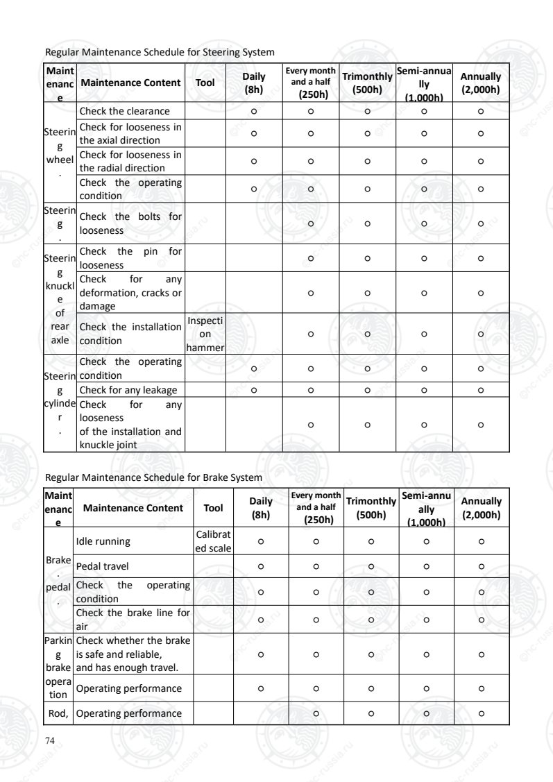
Страница 79
75
Maint
enanc
e
Maintenance Content Tool Daily
(8h)
Every month
and a half
(250h)
Trimonthly
(500h)
Semi-annu
ally
(1,000h)
Annually
(2,000h)
dragli
ne,
and
other
s
Check the joint for
looseness ○ ○ ○ ○
Pipeli
ne
.
Damage, leaks, cracks ○ ○ ○ ○
Check the joints and
clamping parts for any
looseness
○ ○ ○ ○
Brake
maste
r
cylind
er
,
Whee
l
cylind
er
Brake
maste
r
cylind
er
,
Whee
l
cylind
er
Check for any leakage ○ ○ ○ ○
Check the oil level, or
change it ○ ○ ○ × ×
Operating condition of
brake master cylinder
and wheel cylinder
○
Check the brake master
cylinder and wheel
cylinder for any leaks or
damage
○
Check the brake master
cylinder, piston cup and
non-return valve for any
wear or damage and
replace if necessary.
×
Brake
drum
.
and
Brake
shoe
.
Check the components of the
brake drum for any looseness
Inspecti
on
hammer
○ ○ ○ ○
Wear of friction lining Vernier
caliper ○
Operating condition of
the brake shoe ○
Check the fixed pin for
any rusting ○
Check the return spring
for any damage
Calibrat
ed scale ○
Check whether the
clearance is appropriate
during the
operation of the
self-adjusting device
○
Check the brake drum ○
Оригинальная страница: таблицы и схемы
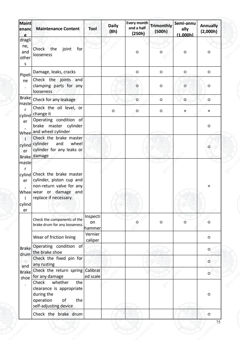
Страница 80
76
Maint
enanc
e
Maintenance Content Tool Daily
(8h)
Every month
and a half
(250h)
Trimonthly
(500h)
Semi-annu
ally
(1,000h)
Annually
(2,000h)
for any wear or damage
Brake
backi
ng
plate
Check for any
deformation ○
Check for any cracks Flaw
detector ○
Check for any looseness
during the installation
Inspecti
on
hammer
○
Regular Maintenance Schedule for Hydraulic System
Maint
enanc
e
Maintenance Content Tool Daily
(8h)
Every month
and a half
(250h)
Trimonthly
(500h)
Semi-annua
lly
(1,000h)
Annually
(2,000h)
Hydra
ulic oil
tank
Check the oil level or
change it (1) ○ ○ ○ ○ ×
Clean the oil
absorption filter (1) ○ ○
Replace the return oil
filter (1) × ×
Clear away any foreign
objects ○ ○
Contro
l valve
stem
Check the joint for
looseness ○ ○ ○ ○ ○
Check the operating
condition ○ ○ ○ ○ ○
Filter Check for any leakage ○ ○ ○ ○
Multi
-way
valve
Check for any oil
leakage
○ ○ ○ ○ ○
Safety valve and tilt
self-locking valve
Check the operating
condition
○ ○ ○ ○
Measure the safety
valve pressure
Oil
pressure
gauge
○ ○
Pipelin
e
.
joint
.
Check for any leakage,
looseness, fracture,
deformation or
damage
○ ○ ○ ○
Replace the pipe ×
1-2 years
Оригинальная страница: таблицы и схемы
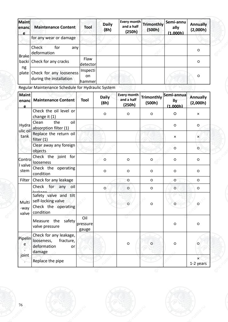
Страница 81
77
Regular Maintenance Schedule for Electrical System
Maint
enanc
e
Maintenance Content Tool Daily
(8h)
Every month
and a half
(250h)
Trimonthly
(500h)
Semi-annua
lly
(1,000h)
Annually
(2,000h)
Starti
ng
motor
Gear engagement ○ ○ ○
Stora
ge
batter
y
Check the electrolyte
level and add more
distilled water if
necessary.
○ ○ ○ ○ ○
Clean the storage
battery ○ ○ ○ ○
Wires
Wire harness damage,
any looseness
.
○ ○ ○ ○
Any looseness in
circuit connections ○ ○ ○
Steeri
ng
indica
tor
light
Check the operating
and installation
condition
○ ○ ○ ○ ○
Horn
Check the operating
and installation
condition
○ ○ ○ ○ ○
Lights
and
bulbs
Check the operating
and installation
condition
○ ○ ○ ○ ○
Backu
p
buzze
r
Check the operating
and installation
condition
○ ○ ○ ○ ○
Displa
y
Check the operating
condition ○ ○ ○ ○ ○
Regular Maintenance Schedule for Lifting System
Maint
enanc
e
Item
Maintenance Content Tool Daily
(8h)
Every month
and a half
(250h)
Trimonthly
(500h)
Semi-annu
ally
(1,000h)
Annually
(2,000h)
Chain
.
,
Chain
wheel
Check the chain tension and
check for any deformation,
damage or rust.
○ ○ ○ ○ ○
Lubricate the chain ○ ○ ○ ○
Check the riveted pin for
any looseness ○ ○ ○ ○
Check the chain wheel for
any deformation or damage ○ ○ ○ ○
Оригинальная страница: таблицы и схемы
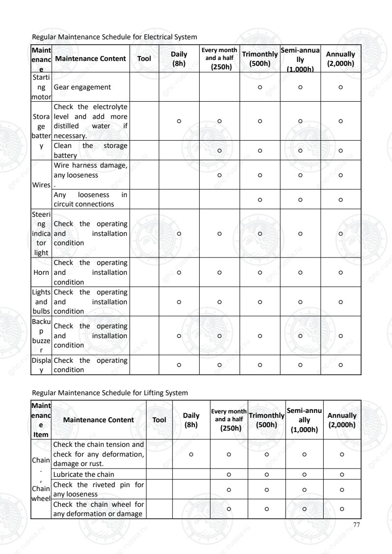
Страница 82
78
Maint
enanc
e
Item
Maintenance Content Tool Daily
(8h)
Every month
and a half
(250h)
Trimonthly
(500h)
Semi-annu
ally
(1,000h)
Annually
(2,000h)
Check the chain wheel gear
for any looseness ○ ○ ○ ○
attac
hmen
ts
Check the operating status ○ ○ ○ ○
Liftin
g
cylind
er
.
Tilt
cylind
er
.
Check the piston rod, the
thread and joint for any
looseness, deformation or
damage.
Inspecti
on
hamme
r
○ ○ ○ ○ ○
Check the operating
condition ○ ○ ○ ○ ○
Check for any leakage ○ ○ ○ ○ ○
Check the pin and
steel-backed bearing of the
cylinder for any wear or
damage
○ ○ ○ ○
Hydra
ulic
.
pump
Check the hydraulic pump
for any leakage or noise ○ ○ ○ ○ ○
Check the driving gear of
the hydraulic pump for any
wear and tear
○ ○ ○ ○
Fork
.
Check the forks for any
damage, deformation or
wear
○ ○ ○ ○ ○
Check the stop dowel for
any damage or wear ○ ○ ○
Check the welded part of
the hook at the root of fork
for any cracks or wear
○ ○ ○ ○
Mast
.
Fork
arm
carrie
r
Check the welding between
the inner/outer mast and
beam for any cracks or
damage
○ ○ ○ ○
Check the welded part
between the tilt cylinder
frame and mast for any
poor welding, cracks or
damage
○ ○ ○ ○
Check the inner/outer mast
for any poor welding, cracks
or damage
○ ○ ○ ○
Check the fork arm for any
poor welding, cracks or ○ ○ ○ ○
Оригинальная страница: таблицы и схемы
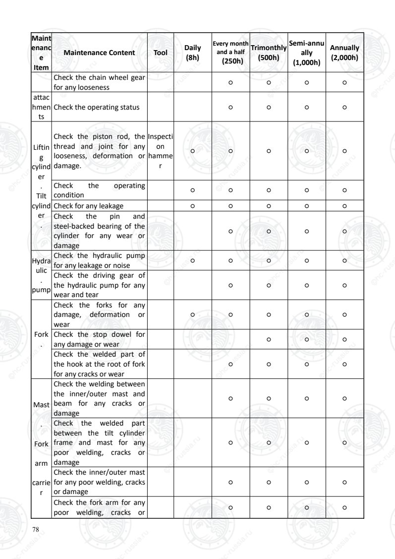
Страница 83
79
Maint
enanc
e
Item
Maintenance Content Tool Daily
(8h)
Every month
and a half
(250h)
Trimonthly
(500h)
Semi-annu
ally
(1,000h)
Annually
(2,000h)
damage
Check the roller for any
looseness ○ ○ ○ ○
Check the bearing shaft
bush of the mast for any
wear or damage
○
Check the bearing cap bolts
of the mast for any
looseness
Inspecti
on
hamme
r
○ ○ ○ ○
Check the bolts at the
bottom of the lifting
cylinder, bolts at the top of
piston rod, U-bolts and the
bolts of the movable beam
guide rail for any looseness
Inspecti
on
hamme
r
○ ○ ○ ○
Check the roller, roller shaft
and welded part for any
cracks or damage
○ ○ ○ ○
Regular Maintenance Schedule for Safety Devices and attachments
Mainten
ance
Item
Maintenance
Content Tool Daily
(8h)
Every month
and a half
(250h)
Trimonthly
(500h)
Semi-annua
lly
(1,000h)
Annually
(2,000h)
Overhea
d
Guard
and
load-
backrest
Check whether they
are secured
Inspectio
n
hammer
○ ○ ○ ○ ○
Check for any
deformation, cracks
or damage
○ ○ ○ ○ ○
Rearvie
w mirror
Check for any dirt or
damage ○ ○ ○ ○ ○
Check the rear
visibility ○ ○ ○ ○ ○
Driver's
seat
Check the bolts for
looseness or
damage
○ ○
Forklift
body
Check the frame and
beam for any
damage or cracks
○
Check the rivets and
bolts for any
looseness
○
Apply Check the
lubrication of the ○ ○ ○ ○
Оригинальная страница: таблицы и схемы
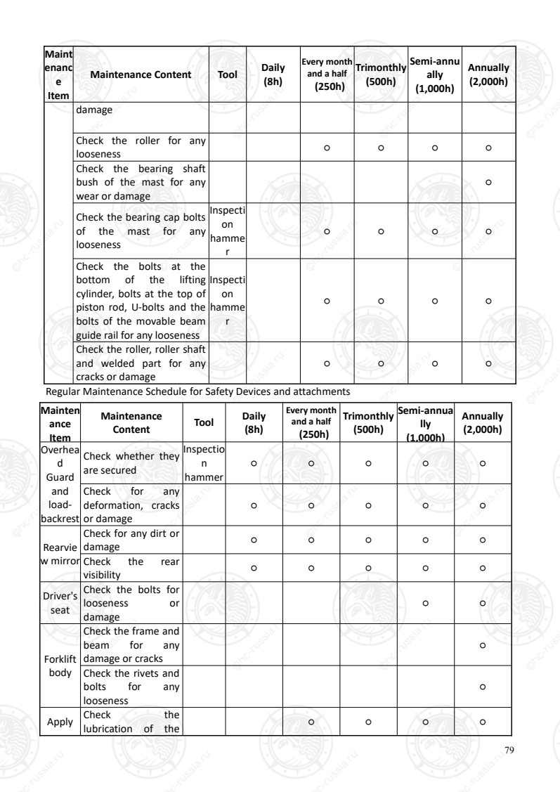
Страница 84
80
Mainten
ance
Item
Maintenance
Content Tool Daily
(8h)
Every month
and a half
(250h)
Trimonthly
(500h)
Semi-annua
lly
(1,000h)
Annually
(2,000h)
lubricati
ng
grease
or
change
the oil
chassis after
cleaning
Check the oil in the
reservoir ○
OPS
system
Check the operating
condition ○ ○ ○ ○ ○
2. Tightening Torque Table of Common Bolts
Nominal
Diameter
mm
Strength Grade
Unit: N·m
4.6 5.6 6.8 8.8
6 4 - 5 5 - 7 7 - 9 9 - 12
8 10 - 12 12 - 15 17 - 23 22 - 30
10 20 - 25 25 - 32 33 - 45 45 - 59
12 36 - 45 45 - 55 58 - 78 78 - 104
14 55 - 70 70 - 90 93 - 124 124 - 165
16 90 - 110 110 - 140 145 - 193 193 - 257
18 120 - 150 150 - 190 199 - 264 264 - 354
20 170 - 210 210 - 270 282 - 376 376 - 502
22 230 - 290 290 - 350 384 - 512 512 - 683
24 300 - 377 370 - 450 488 - 650 651 - 868
27 450 - 530 550 - 700 714 - 952 952 - 1269
30 540 - 680 680 - 850 969 - 1293 1293 - 1723
33 670 - 880 825 - 1100 1319 - 1759 1759 - 2345
36 900 - 1100 1120 - 1400 1694 - 2259 2259 - 3012
39 928 - 1237 1160 - 1546 1559 - 2079 2923 - 3898
Note:
• All key joints use bolts in 8.8 Grade.
• The bolt grade can be found in the head, if not it is 8.8 Grade
Оригинальная страница: таблицы и схемы
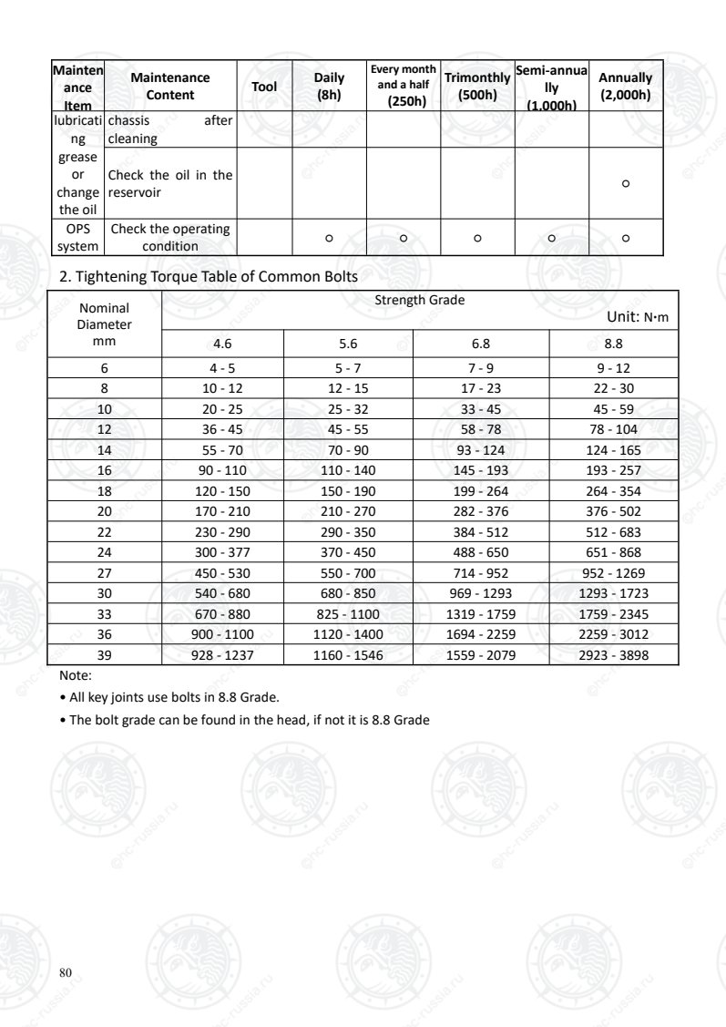
Страница 85
81
3. Regular replacement of key safety parts
It is difficult to find any damage to some parts through regular maintenance, thus in order to ensure
the safety of forklift operation, the user should regularly replace the parts given in the table below.
If the replacement time is not reached and there is any abnormality in these parts, the defective parts
should be replaced immediately.
Key Safety Part Service Life (Years)
Brake hose or rigid pipe l-2
Hydraulic rubber hose for the lifting system l-2
Lifting chain 2 - 4
High-pressure rubber hose and flexible tube for the
hydraulic system 2
Brake fluid reservoir 2 - 4
Fuel hose 2
Sealing parts and rubber parts in the hydraulic
system 2
Оригинальная страница: таблицы и схемы
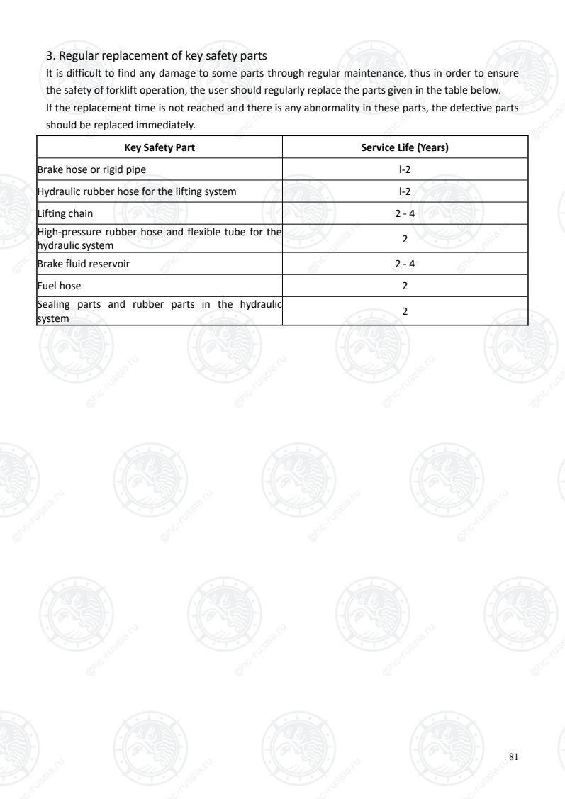
Страница 86
82
4. Forklift Oil List
1.0T-3.8t Forklift Oil List
Name Model/Code Volume (L) Remarks
Gasoline 92#/95#
93#/97#
45 1.0t-1.8t
60 2.0t-3.8t
Diesel 0# (Summer)
-10# to -35# (Winter)
45 1.0t-1.8t
60 2.0t-3.8t
LPG 40
Diesel engine oil
Normal weather: CH-4, 15W/40
Winter: CH-4, 10W/30
Severely cold environments: CH-4,
5W/30,
or refer to the Engine Maintenance
Manual
6.5-7.4 Except for W56
Normal weather: CH-4, 15W/40
Winter: CH-4, 10W/30
Severely cold environments: CH-4
5W-40,
or refer to the Engine Maintenance
Manual
6.3 W56
Diesel engine oil
Normal weather: CI-4 15W/40
Winter: CI-4, 10W/30
Severely cold environments: CI-4
5W-40,
or refer to the Engine Maintenance
Manual
6.5-7.4 China IV Engine
LPG engine oil
Normal weather: SF 15W/40
Winter: SF 10W/30
(Severely cold environments:
Caltex API SAE 5W-40)
or refer to the Engine Maintenance
Manual
3.5-4 K21, K25
Hydraulic oil
L-HM32
(Severely cold environments:
L-HV32)
36 - 41 1.0t-1.8t
45 - 51 2.0t-2.5t
49 - 55 3.0t-3.8t
Automatic
Transmission Fluid
(ATF)
(transmission)
6# Automatic Transmission Fluid
(ATF)
(Severely cold environments: 8#
ATF)
7 1.0t-1.8t XYQXD
Transmission
8.5 2.0t-3.5t XYQXD
Transmission
6.8 1.0t-3.5t XYQXF
Transmission
Great Wall ATF-IIIH (filled before 4.5 1.0t-3.8t Okamura
Оригинальная страница: таблицы и схемы
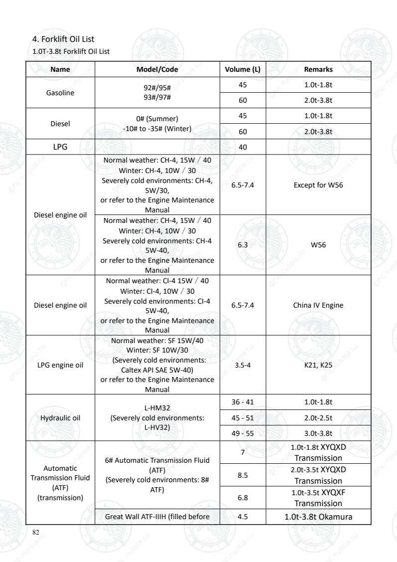
Страница 87
83
Name Model/Code Volume (L) Remarks
leaving the factory)
or the equivalent
in Class DEXRON-III.
Transmission
9 1.0t-3.8t B1 Trucks
Gear oil
85W/90 (GL-5),
(Severely cold environments:
80W/90 (GL-5))
4.5 1.0t-1.8t Mechanical truck
5.4 2.0t-2.5t Mechanical truck
10.3 3.0t-3.8t Mechanical truck
4.5 1.0t-1.8t Hydraulic truck
5 2.0t-2.5t Hydraulic truck
5.8 3.0t-3.8t Hydraulic truck
Brake fluid
(Added to brake
fluid reservoir)
Choice HZY3 brake fluid (filled
before leaving the factory) or DOT3
brake fluid
1.5
Antifreeze (water
tank) FD-2 multi-effect antifreeze coolant 10 - 11 1.0t-3.8t
Industrial vaseline 2# Battery electrode pole
Grease
(each lubrication
point)
General purpose automotive
lithium grease
Оригинальная страница: таблицы и схемы
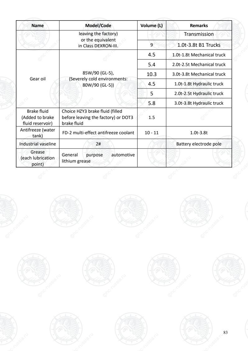
Страница 88
84
4.0t-X5.0t Forklift Oil List
Name Model/Code Volume (L) Remarks
Gasoline 92#/95#
93#/97# 80
Diesel
O# (summer) (w58 sulphur content:
<15ppm)
-10# to -35# (winter)
80
(Cummins
w58 sulphur content: <
15ppm)
LPG 40
Diesel engine oil
Normal weather: CH-4, 15W/40
Winter: CH-4, 10W/30
Severely cold environments: CH-4
5W/30,
or refer to the Engine Maintenance
Manual
12 Except for G93 and G82
Normal weather: CI-4 15W/40
Winter: CI-4, 10W/30
Severely cold environments: CI-4,
5W/30);
or refer to the Engine Maintenance
Manual
12 G93 engine
APE SAE 15W/40,CJ-4/SJ
≈11
See the
engine
manual or
dipstick scale
for specific
filling amount
Low-ash engine oil
G82
Gasoline engine
oil
Normal weather: SF 15W/40
Winter: SF 10W/30
(Severely cold environments: Caltex
API SAE 5W/40)
or refer to the Engine Maintenance
Manual
12 W57
Hydraulic oil
L-HM32
(Severely cold environments:
L-HV32)
About 80
When the mast is lifted by 1
meter,
5-5.5 liters of hydraulic oil
should be added.
Automatic
Transmission Fluid
(ATF)
6# Automatic Transmission Fluid
(ATF) 12 Except for trucks used for
handling stones
ATF3 12
CPCD55-XRXG73BN-S
CPCD55-XRXG76BN-S
CPCD55-XRXG82BN-S
Gear oil
85W/90 (GL-5),
(Severely cold environments:
80W/90 (GL-5) or 70W/90)
5.5 Hydraulic truck: for drive axle
14
Mechanical truck: 7 liters for
drive axle and mechanical
transmission respectively
Оригинальная страница: таблицы и схемы
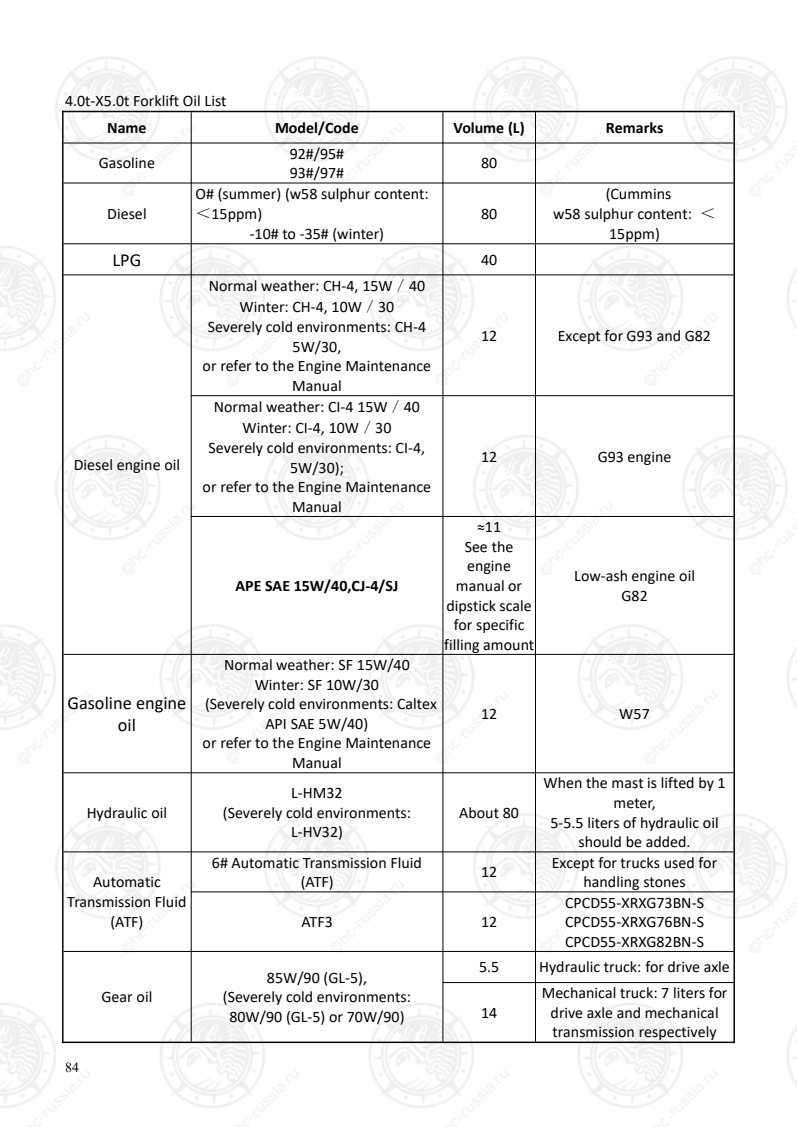
Страница 89
85
Mobil ATF 424 8
CPCD55-XRXG73BN-S
CPCD55-XRXG76BN-S
CPCD55-XRXG82BN-S
Brake fluid
Choice HZY3 brake fluid (filled before
leaving the factory) or DOT3 brake
fluid
1.5
Antifreeze coolant FD-2 multi-effect antifreeze coolant 18
Industrial vaseline 2# Battery electrode pole
Grease
(each lubrication
point)
General purpose automotive lithium
grease
Note:
• The forklift truck was filled with anti-rust and antifreeze coolant at the factory. It is not necessary to
drain the coolant even in winter. Fill its reservoir to the required level if necessary and change it once
every 2-4 years.
• If the forklift truck was not filled with anti-rust and antifreeze coolant at the factory, the user should
add it as required. In winter, the cooling water must be drained out of forklift trucks not filled with
anti-rust and antifreeze coolant.
Different brands of oil should not be mixed and used together.
- The quality of diesel oil should comply with GB 19147-2016, and the sulfur content of diesel oil
should not be greater than 10mg/kg.
- Great Wall hydraulic oil, ATF, and gear oil are added before the truck leaves the factory.
Recommended viscosity of diesel engine oil at different ambient temperatures
Recommended viscosity of gasoline engine oil at different ambient temperatures
Оригинальная страница: таблицы и схемы
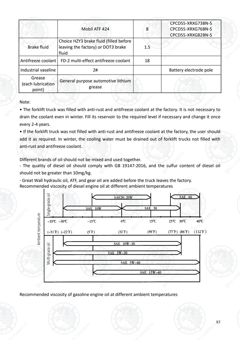
Страница 90
86
Оригинальная страница: таблицы и схемы
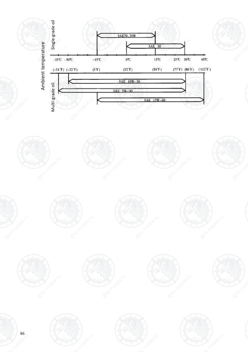
Страница 91
87
5. Lubricating System Diagram
LUBRICATION SYSTEM CHART
Note: 1. Please refill the truck with the specific lubrication oil according to the specific truck model
based on the Forklift Oil List.
2. Refer to the Weekly Maintenance (40h) for the lubrication of the mast and chain.
Environmental protection:
1. Clean, maintain and repair the vehicle at the designated place.
2. Before dismantling the pipeline, joints or related parts, special containers should be used to receive
used fluids (including coolant, engine oil, hydraulic oil, transmission oil, ATF, brake fluid, grease, etc.)
and used batteries.
3. The used oil/fluid should be recycled according to the local environmental protection laws and
regulations to prevent pollution of the environment, rather than poured away or disposed of at will.
Safety awareness:
The temperature of coolant, engine oil, hydraulic oil, transmission oil and ATF after a long operation is
Оригинальная страница: таблицы и схемы
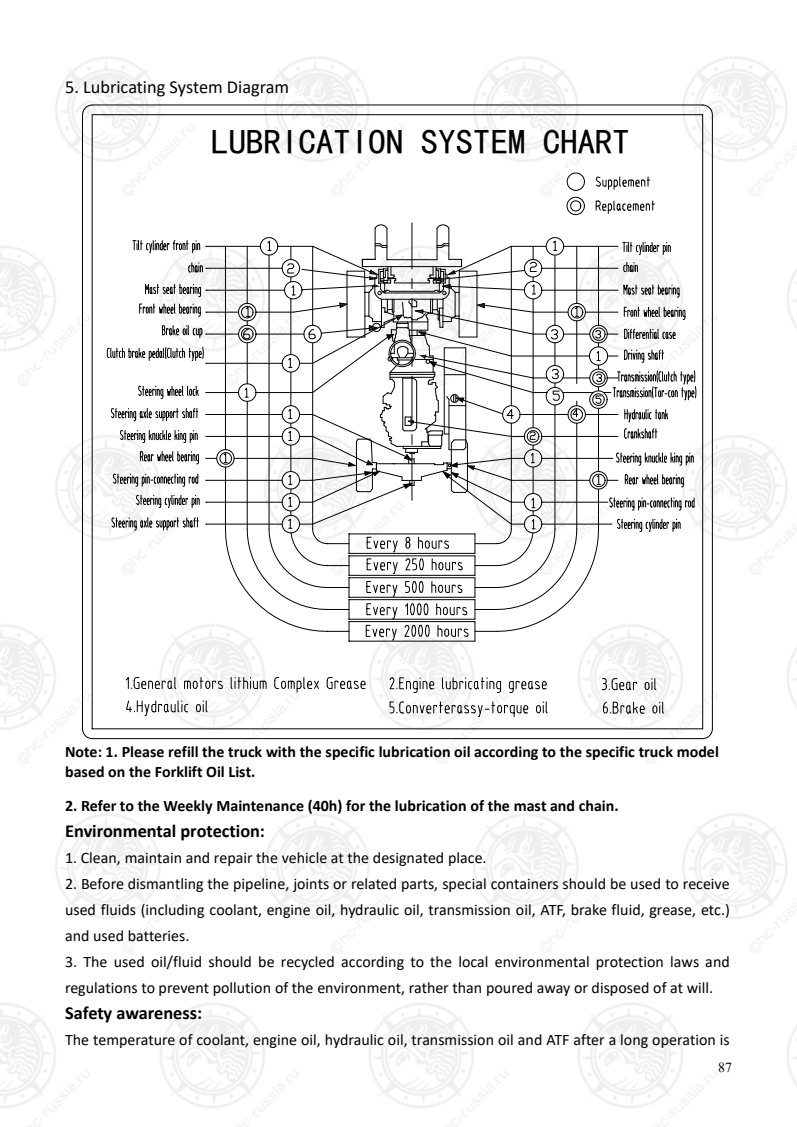
Страница 92
88
very high, the oil change should not be carried out until the temperature drops below 70 ℃ ; skin
should be protected, otherwise the oil will burn or corrode the skin.
Оригинальная страница: таблицы и схемы

Страница 93
89
IX. Various signs/labels: various signs or labels are affixed to
different parts of the forklift truck.
The 1-3.8t truck is taken as an example, the 4-X5t truck is similar.
内 燃 平 衡 重 式 叉 车
最大起升高度起重量
客服电话:
装有属具时,最大起升高度起重量参见属具标牌或载荷曲线标牌
标准载荷中心距
中国浙江临安经济开发区东环路 号
无属具
整机编号
型号 规格
载荷中心距最大起升高度
杭叉集团股份有限公司
额定起重量
自      重
许可证号:
发动机额定功率 kW /r/m in
DPF相关指示说明
为满足GB20891-2014第四阶段排放标准,本车装载了DPF(颗粒捕集器),请注意以下事项:
·必须使用GB19147标准的柴油,合格的CJ级专用机油,否则会造成DPF过快堵塞和催化剂中毒失效。
·行车时请注意以下指示灯,灯亮时请尽快进行人工干预,否则会影响车辆正常运行。
再生禁止灯:
灯亮时,DPF无法进行再生。
注意! 进入 加油 站等 易燃 易爆 区域 时务 必开 启此灯 ,
离开危 险区 域后 务必 关闭 此灯 ,否 则容 易导 致DPF堵 塞。
再生状态灯:
灯亮时,DPF正处于再生状态。
排气系统故障指示灯:
灯亮时,请联系售后处理。
排气高温报警灯:
灯亮时,排气温度过高,排气系统故障。
注意! 此时 请停 止再 生状 态, 并到 服务 站清 理。
再生提醒灯:
共有熄灭、常亮、慢闪和快闪四种状态。常亮时说明DPF轻度过载,请提高发动机转速行车再生或停车按要求进行
驻车再生。若车辆保持长时间轻载运行,请停车使用驻车再生。慢闪、快闪时建议根据下图进行人工干预。
驻车再生说明:
    进行驻车再生前,叉车需停放在通风良好的平
坦路面,发动机需处于热机怠速状态,挂空挡拉手
刹,松开油门踏板,确保再生禁止未开启,无DPF及
发动机相关故障,长按两秒驻车再生开关进入再生。
再生时发动机转速将提高,约20-40分钟后再生结
束,发动机回到怠速。
    如果遇到紧急状况必须停止驻车再生,只需操
作手刹、换挡开关、油门踏板和禁止再生开关中任
意一项,即退出再生状态。
注意! 此时 用户 无需 进行 操作 ,车 辆需 远离
易燃易 爆区 域。
排放控制诊断系统
115psi
7.9bar
6.50-10-10PR
140psi
9.7bar
28X9-15-14PR
警  告
离开座椅前
须拉紧手刹
1. Hazard label 2. Lifting label 3. Lifting label 4. Safety belt label
5. No flushing label 6. Noise mark 7. Load curve sign 8. Hydraulic oil label
9. Cutting and
clamping labels 10. Antifreeze label 11. LPG label 12. Typeface label
13. Tie-down point
label
14. Tire pressure
label 15. Diesel label 16. Gasoline label
17. Tonnage label 18. Warning label 19. Control label 20. Hand brake label
21. Product
nameplate
22. Lubricating
system label 23. Hazard label 24. Hazard label
25. Regen operating instruction label 26. DPF warning label 27. China IV emission
label
28. Emission control diagnosis system label 29.“PRO”label 30.Passenger
prohibition label
31.Hand brake label 32.Card swiping label
Оригинальная страница: таблицы и схемы
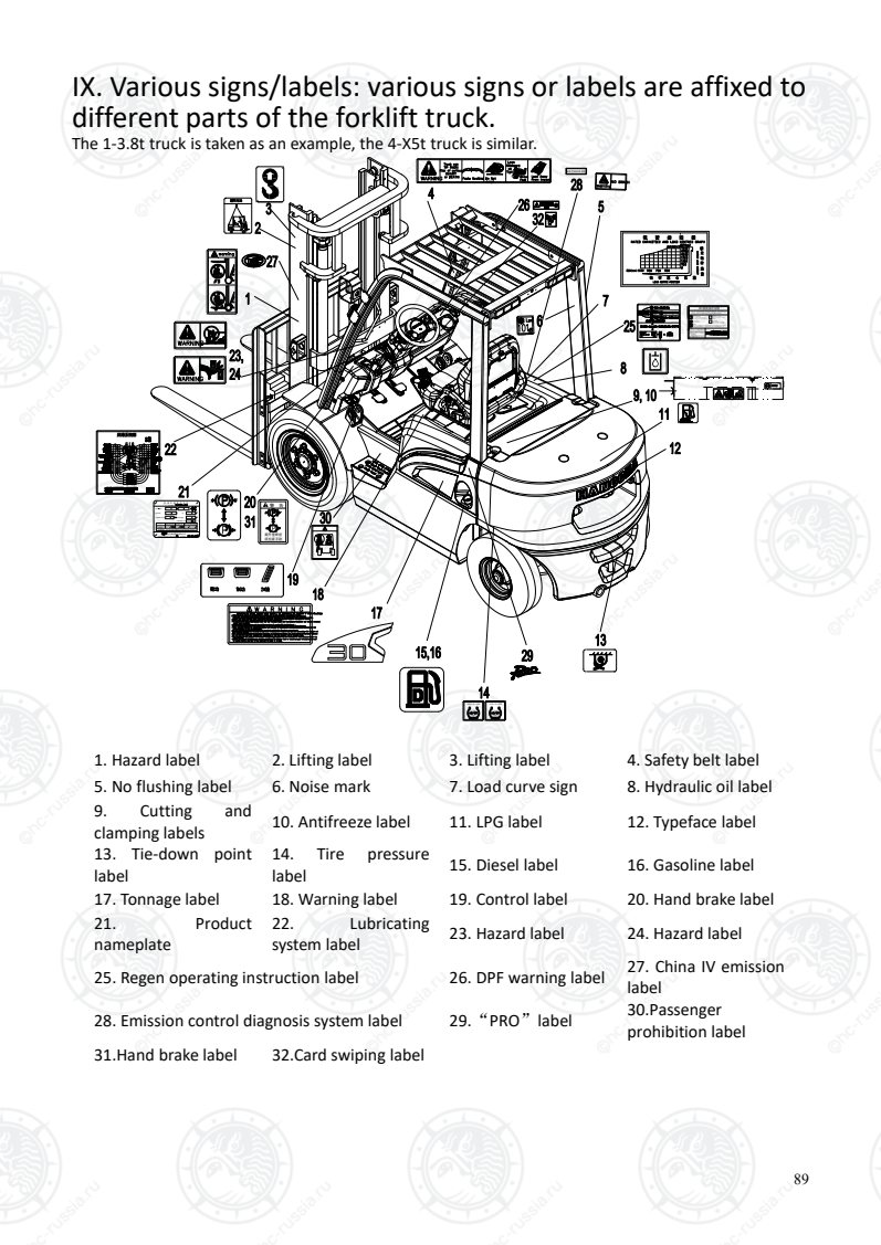
Страница 94
90
A
B
A. Frame S/N. B. Mechanical environmental protection code
Оригинальная страница: таблицы и схемы
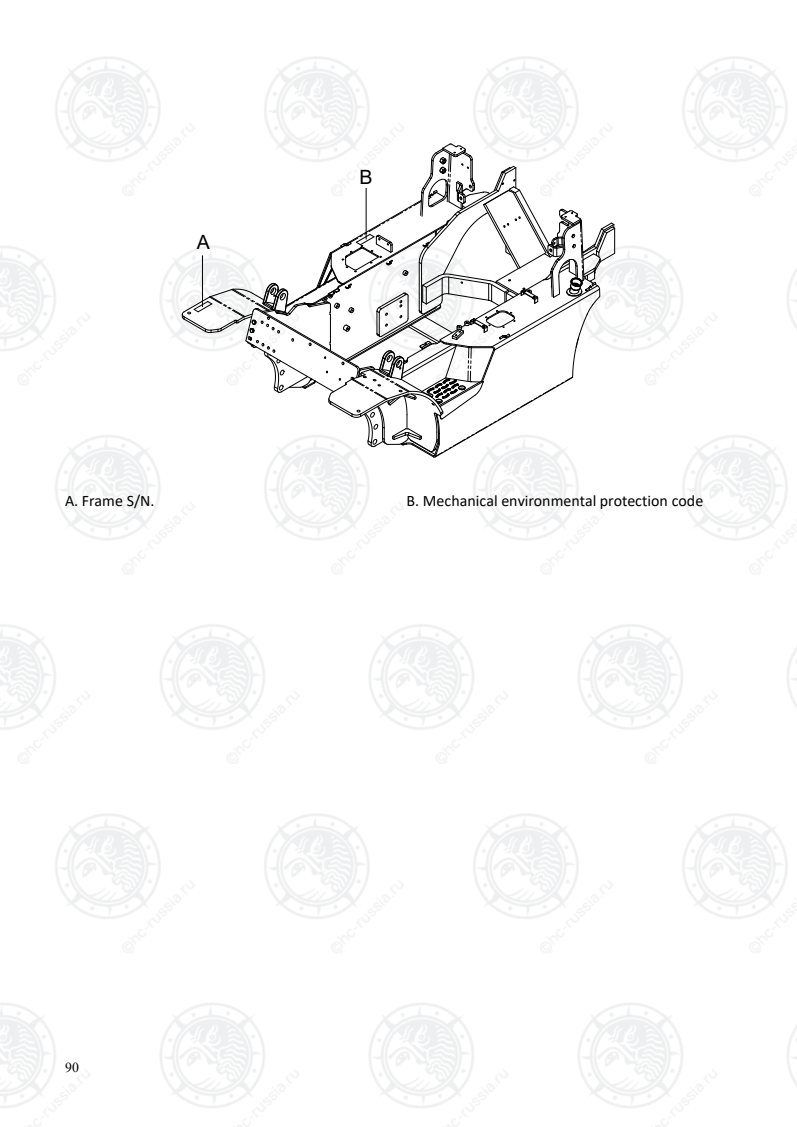
Страница 95
91
1. Hazard label: Stuck on the outer mast
Do not stand on or under the fork arm carrier;
otherwise, your safety will be at risk.
2. Lifting label: Indicates the lifting position and
method of the truck. When lifting, prevent the
rope from rubbing and damaging the lamp.
3. Lifting label: Indicates the lifting position and
method of the truck. When lifting, prevent the
rope from rubbing and damaging the lamp.
4. Safety belt label (anti-tilting warning label)
WARNING Faste Seatblet Do Not Jump! Brace
Feet
Hold
 on
Tight
 Lean Away
 From Impact
Truck can
TIP OVER!
Risk of serious
INHURY
 or DEATH!
5. No flushing label. It is on the right leg of the
right safety shelf by the engine air intake; there
should be no water allowed near the intake
when flushing the truck.
6. Noise label
1.0t-3.5t
WAL WAL
4.0t-X5.0t
LWA
7. Load curve sign
It shows the relationship between the location
Оригинальная страница: таблицы и схемы
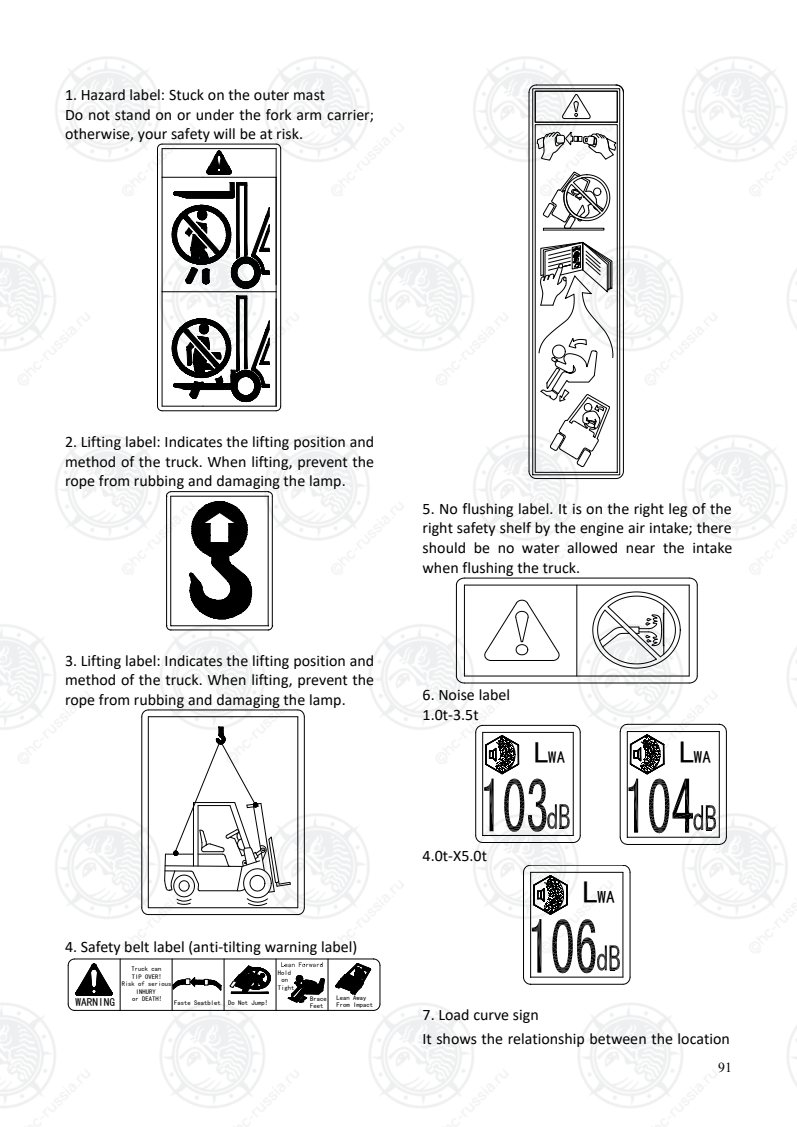
Страница 96
92
of the load center distance and the maximum
load or maximum lift height.
The load capacity of trucks with a sideshifter
and attachments is reduced. When the lift
height is increased, the load capacity will
decrease. Check whether the load and the load
center distance are within the allowable range
of the Bearing Capacity Chart before loading. If
the load shape is complicated, the heaviest
part should be placed in the center of the fork
and close to the load-backrest.
2-stage mast
3-stage mast
8. Hydraulic oil label
9. Fan cutting and clamping labels
10. Antifreeze label
11. LPG label (only LPG trucks and dual fuel
vehicles)
The label is affixed to the cylinder.
Marks the maximum weight (52kg) of the LPG
tank
Maximum LPG pressure (2.2MPa)
Maximum weight (105kg) borne by the
support
13. Tie-down point label
14. Tire pressure label
OLD:
1.5t~1.8t
TIRE PRESSURE
115psi
FRONT
7.9bar
REAR
145psi
10bar
Оригинальная страница: таблицы и схемы
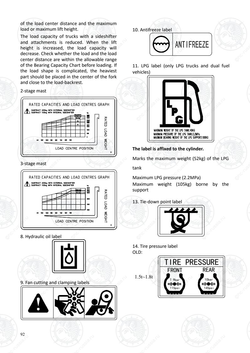
Страница 97
93
2.0t~2.5t
TIRE PRESSURE
125psi
FRONT
8.6bar
REAR
125psi
8.6bar
3.0t~3.5t
TIRE PRESSURE
140psi
FRONT
9.7bar
REAR
115psi
7.9bar
4.0t~X5t
TIRE PRESSURE
FRONT REAR
120psi
8.3bar
125psi
8.6bar
NEW:
1.5t~1.8t
145psi
10.0bar
5.00-8-10PR 7.00-12-14PR
21×8-9-16PR8.25-15-18PR
18×7-8-16PR 16×6-8-16PR
115psi
7.9bar
6.50-10-10PR
2.0t~2.5t
125psi
8.6bar
7.00-12-12PR
6.00-9-10PR
3.50-5-6PR
125psi
8.6bar
7.00-12-12PR
6.00-9-10PR
3.50-5-6PR
3.0t~3.5t
115psi
7.9bar
6.50-10-10PR
140psi
9.7bar
28X9-15-14PR
4.0t~X5t
125psi
8.6bar
7.00-12-12PR
6.00-9-10PR
3.50-5-6PR
120psi
8.3bar
8.25-15-14PR
300-15-18PR
355/65-15-24PR
15. Diesel label: Indicates that the oil filler is on
the left rear leg of the overhead guard.
(No such label on gasoline trucks and LPG
trucks)
16. Gasoline label: Indicates that the oil filler is
on the left rear leg of the overhead guard.
(No such label on diesel trucks and single
fuel LPG trucks)
17. Tonnage label
“30” indicates that the Rated load capacity is
3.0t, but if the lift height is increased or there
are attachments, the Rated load capacity will
decrease.
18. Warning label
Do not load lift truck over capacity limit designated on the load chart.Do not lift unstable loads.
This lift truck is not designed for raising or transporting people.Do not use lift truck for those purposes under any
   Before you get off lift truck,made sure the hand brake is set,lower forks or attachments,put forward/reverse lever
  in neutral position and turn off key switch.Do not park on a slope.
 circumstances.
Repair work should be done by authorized and trained persons only.
W A R N I N G
SERIOUS OR FATAL INJURY MAY RESULT TO YOURSELF OR OTHERS IF NOT FOLLOWED
   This lift truck should not be operated by anyone who is not authorized and properly trained.
   Read the Operators Manual and all warnings carefully,and make yourself familiar with your lift truck.
Inspect and check your lift truck daily before and after use.Do not operate faulty or damaged lift trucks.
 To protect from falling objects,make sure that the Overhead Guard and Load Backrest Extension are correctly mounted
   and in good condition.
Before starting engine,always set forward/reverse lever in neutral,with hand brake on .
Drive carefully,keeping forks and attachments as low as possible & fully tilted backp-Never Forward
  Keep a careful lookout for people,obstructions and the path of travel.Watch clearance,especially overhead and tail
  swing.Yield right of way to pedestrians.
Drive forward when you are climbing a slope with a load .Drive in reverse when you are descending with loads.Do not
 Slow down before turning.Avoid any sudden start,stop or turning.Lateral tipover can occur if truck is improperly operated.
Do not stick hands,feel and other parts lf your body outside the Operators compartment.
   Operator's Manual and Service Manual are supplied with this truck or available from our forklift truck dealers.
 turn while on a slope.
19. Control label 1 (hydraulic trucks only)
BRAKEINCHING ACCELERATOR
Control label 2 (mechanical trucks only)
Оригинальная страница: таблицы и схемы
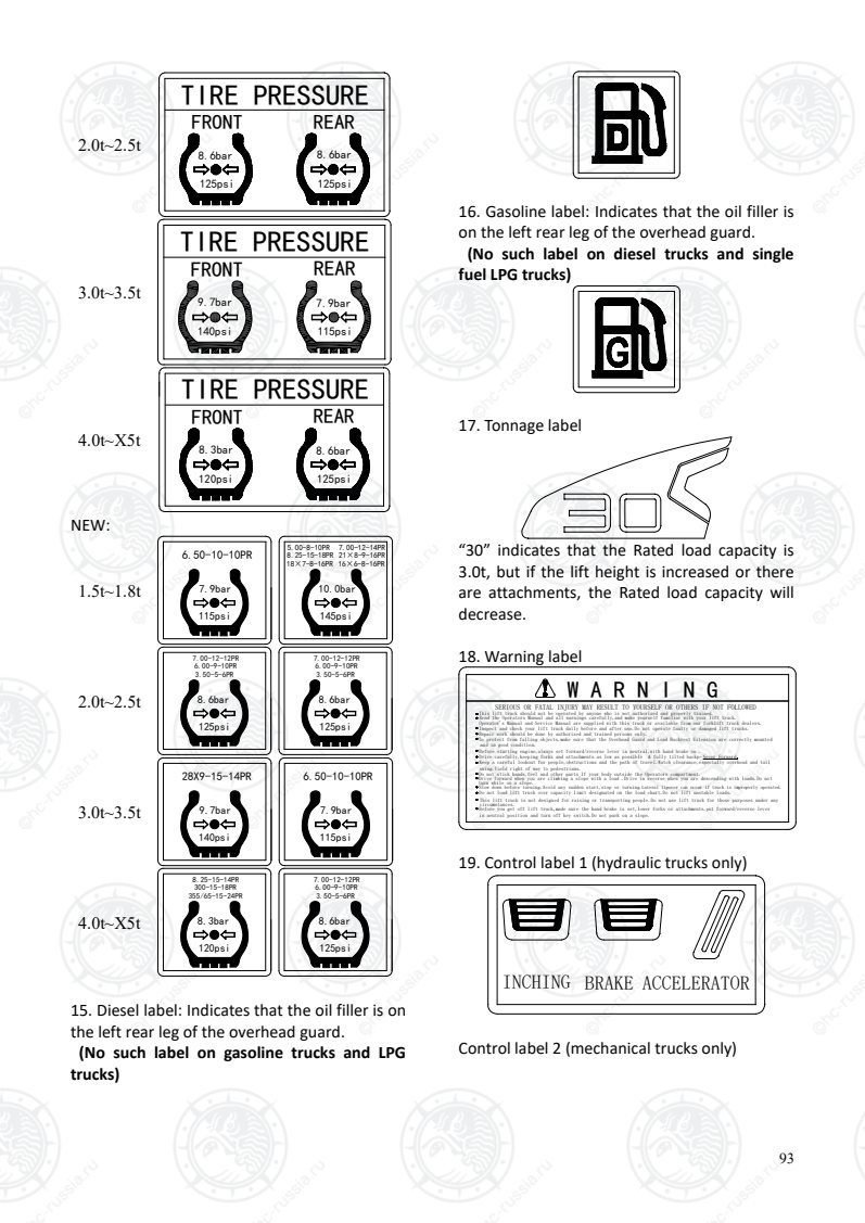
Страница 98
94
BRAKECLUTCH ACCELERATOR
20. Hand brake label
21、Product nameplate
CE nameplate
Ⅲ
Ⅰ Ⅱ
China IV nameplate
达到GB20891-2014第四阶段排放标准
机械类型:工程机械
发动机型号:
环保
关键
零部件
环 保 信 息 标 签
基
本
信
息
燃料喷射系统型式:
发动机生产企业名称:
商标:
型号规格配置: 名称:内燃平衡重式叉车
制造日期:
Ⅰ
Ⅻ XIII
XIIII
XV
Ⅹ
、杭叉、
环保信息公开编号:
kW/r/min
最大起升高度起重量
装有属具时,最大起升高度起重量参见属具标牌或载荷曲线标牌
标准载荷中心距
无属具
载荷中心距最大起升高度
mm mm
mm
额定起重量
kg
kg
发动机
额定功率
客服电话:400-884-7888浙江省杭州市临安区相府路666号
内 燃 平 衡 重 式 叉 车
许可证编号:TS2510002-2024特种设备代码:
自重 kg型号
产品编号
配置号
生产企业名称:杭叉集团股份有限公司
English nameplate
Оригинальная страница: таблицы и схемы
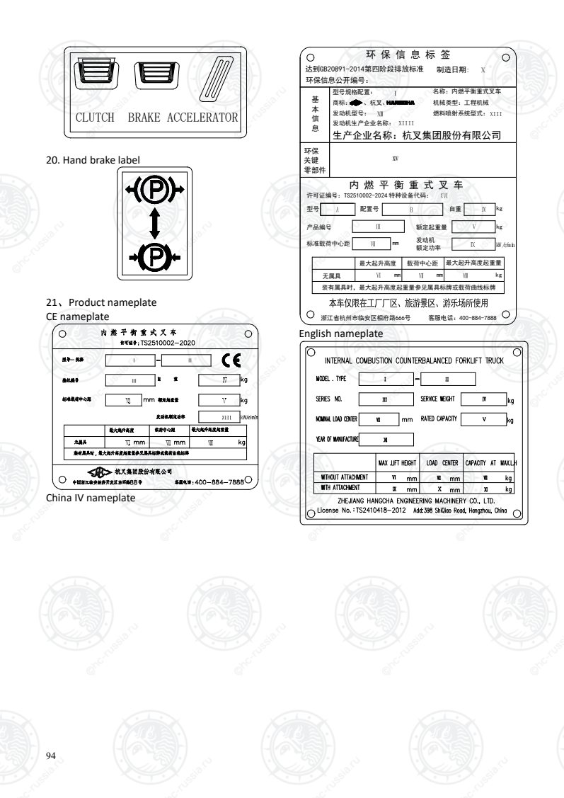
Страница 99
95
22. Lubricating system label
LUBRICATION SYSTEM CHART
23. Hazard label
Inner and outer masts and fork arm carriers are
sliding parts for lifting and lowering; do not
place your hands between the inner and outer
masts.
If it is necessary to inspect or repair this part,
the inspection and repair can only be carried
out after the engine is turned off. There must
be no other people on the truck; people
outside the truck should not operate the truck
to avoid an accident arising from misuse of the
mast lever.
24. Hazard label (Keep clear of mast label)
Warning: Danger to your life. If you become
trapped between the mast and instrument
stand or overhead guard, you will be at risk of
serious injury. If it is necessary to inspect or
repair this part, the inspection and repair can
only be carried out after the engine is turned
off. There must be no other people on the
truck; people outside the truck should not
operate the truck to avoid an accident arising
from misuse of the mast lever.
25、Regen operating instruction label (4t-5t
China IV trucks only)
Before updating:
After updating:
For guidance on correctly operating the truck for
regen., please refer to the regen. related content as
described under China IV Instruments of this Manual.
26、DPF warning label (4t-5t China IV trucks
only)
27、China IV emission label (China IV trucks
only)
Оригинальная страница: таблицы и схемы
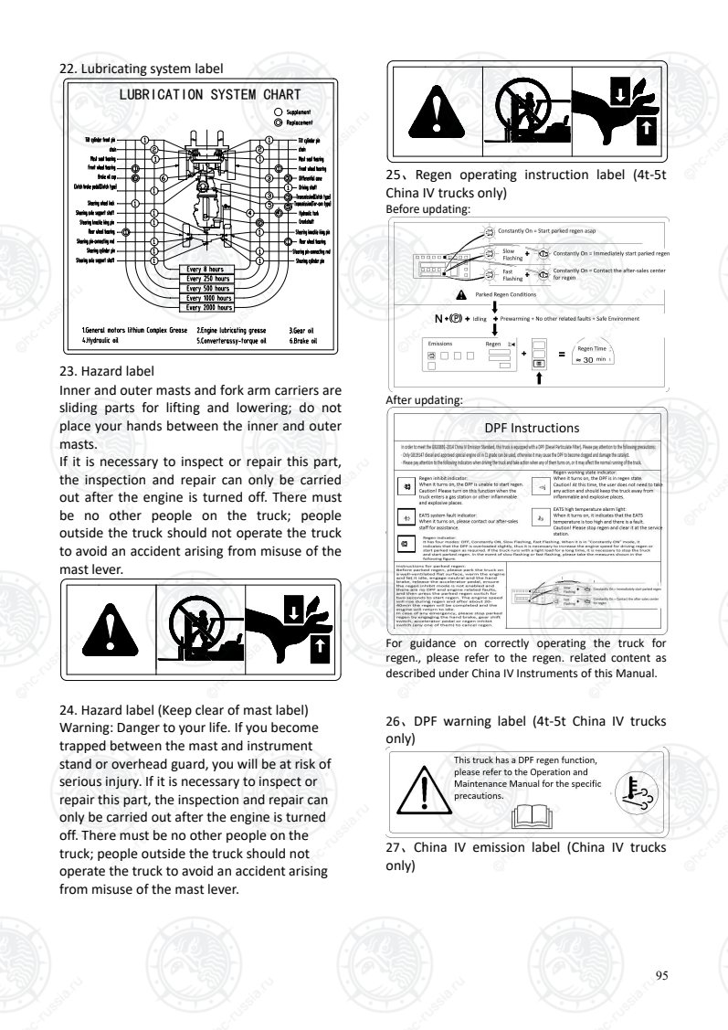
Страница 100
96
28、Emission control diagnosis system label
(China IV trucks only)
Stuck on the right side of hood.
29、“Pro”label
30、Passenger prohibition label
31、Hand brake label(Chinese)
警  告
离开座椅前
须拉紧手刹
32、Card swiping label(Chinese)
33、Marking positions for frame S/N
A
B
A. Frame S/N B. Mechanical
environmental
protection code
Оригинальная страница: таблицы и схемы
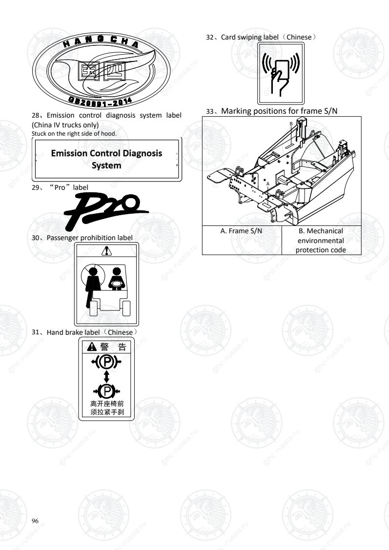
Страница 101
97
X. Lifting, handling and towing of the forklift truck
Lift the forklift truck
•Tie the steel rope on the lifting hole and counterweight lifting hook at both ends of the beam of
outer mast firmly and lift the forklift truck with the lifting device.
Warning
• Do not wind the steel rope around the overhead guard when lifting the forklift truck.
• The steel rope and the lifting device must be strong enough to safely support the forklift truck,
because the truck is extremely heavy.
• Do not lift the forklift truck with the cab frame (overhead guard).
•Do not stand under the forklift truck when lifting it.
Handling
The forklift truck can be used for loading and unloading and short distance transport, but should not
be used for long distance transport. If the forklift truck is transported over a long distance, it should be
handled with a ship, train or vehicle with load capacity of more than 5t. Chock the wheels with
wedges firmly and tie the body down firmly at the same time to protect the truck from sliding during
transport.
Towing
The drag pin under the counterweight can only be used for pulling the forklift truck; the drag pin
should be pulled out first when towing; then, the steel rope should be installed, and the drag pin
should be reinstalled.
Note: Release the hand brake lever.
Towing method after truck damage:
Release the hand brake lever. Pull the shift lever into the neutral position. Pay attention to traffic
safety and hang the towing sign.
Оригинальная страница: таблицы и схемы
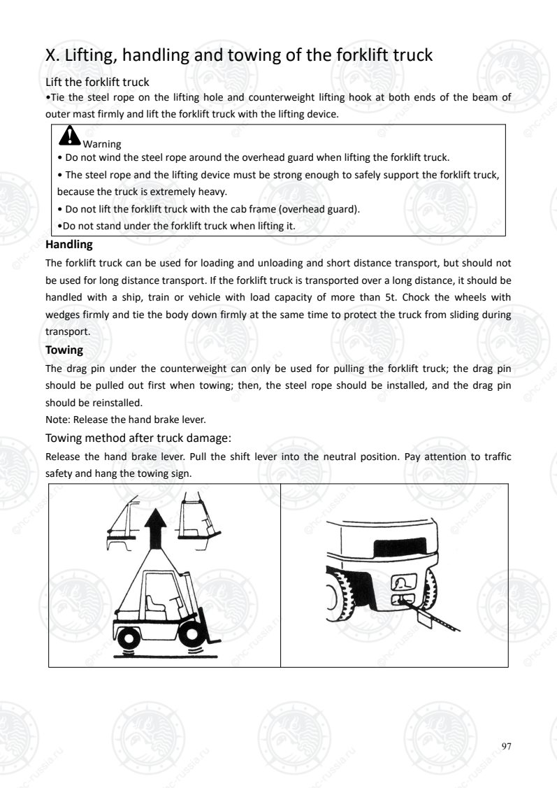
Страница 102
98
Caution
• Do not tow trucks with defective steering systems or damaged brake systems.
• Obey traffic rules when towing a truck on the highway.
Warning
• Only attach the steel rope to the specified position.
• Do not suddenly apply load on the steel rope.
Оригинальная страница: таблицы и схемы
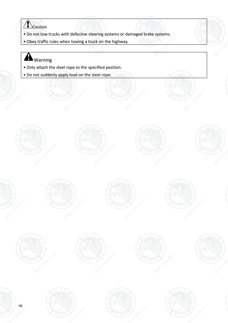
Страница 103
99
XI. Model meaning
Note: The truck with B1 transmission and the truck with F transmission have the same engine model.
Apart from the transmission models, the other parts of them are the same.
1t-1.8t
Model Engine Hydraulic/mechanical
transmission
Rated Lift Capacity (t)
/
Load center distance
(mm)
RemarksCPC10/15/18-XRG71
4D27XG30-003
Diesel engine
XR150-120000-G00 1/500, 1.5/500,
1.8/500
CPCD10/15/18-XRG71 XR160-120000-G00 1/500, 1.5/500,
1.8/500
CPCD10/15/18-XRG71F XRF160-120000-G00 1/500, 1.5/500,
1.8/500
CPC10/15/18-XRG71J
4D27XG40-001
Diesel engine
XR150-120000-G00 1/500, 1.5/500,
1.8/500
CPCD10/15/18-XRG71J XR160-120000-G00 1/500, 1.5/500,
1.8/500
CPCD10/15/18-XRG71JF XRF160-120000-G00 1/500, 1.5/500,
1.8/500
CPCD15/18-XRG71JB1 XRB1630-120000-G00 1.5/500, 1.8/500
CPC15/18-XRW10
ISUZU
GK-C240NKFC-0
1
XR150-120000-G00 1.5/500, 1.8/500
CPCD15/18-XRW10 XR161-120000-G00 1.5/500, 1.8/500
CPCD15/18-XRW10B(B1) B:Y43160X-000-G00
B1:XRB1630-120000-G00 1.5/500, 1.8/500
CPCD15/18-XRW10F XRF160-120000-G00 1.5/500, 1.8/500
CPCD15/18-XRW43
Cummins
QSF2.8T3NA49
Diesel engine
XR161-120000-G00 1/500, 1.5/500,
1.8/500
CPQD15/18-XRW21
K21 Gasoline
Engine GCT
XR161-120000-G00 1.5/500, 1.8/500
CPQD15/18-XRW21F XRF160-120000-G00 1.5/500, 1.8/500
CPQYD15/18-XRW21 XR161-120000-G00 1.5/500, 1.8/500
CPQYD15/18-XRW21F XRF160-120000-G00 1.5/500, 1.8/500
CPCD15/18-XRW91F 4D27XG30-300
Diesel engine XRF160-120000-G00 1.5/500, 1.8/500
CPQD15/18-XRW21B(B1) K21 Gasoline
Engine GCT
B:Y43160X-000-G00
B1:XRB1630-120000-G00
1.5/500, 1.8/500
CPQYD15/18-XRW21B(B1) 1.5/500, 1.8/500
CPCD15/18-XRG98 4D29X41-008
Diesel engine XR160-120000-G00 1.5/500, 1.8/500
CPCD15/18-XRG98F 4D29X41-007
Diesel engine
XRF160-120000-G00 1.5/500, 1.8/500
CPCD15/18-XRG98B1 XRB1630-120000-G00 1.5/500, 1.8/500
Оригинальная страница: таблицы и схемы
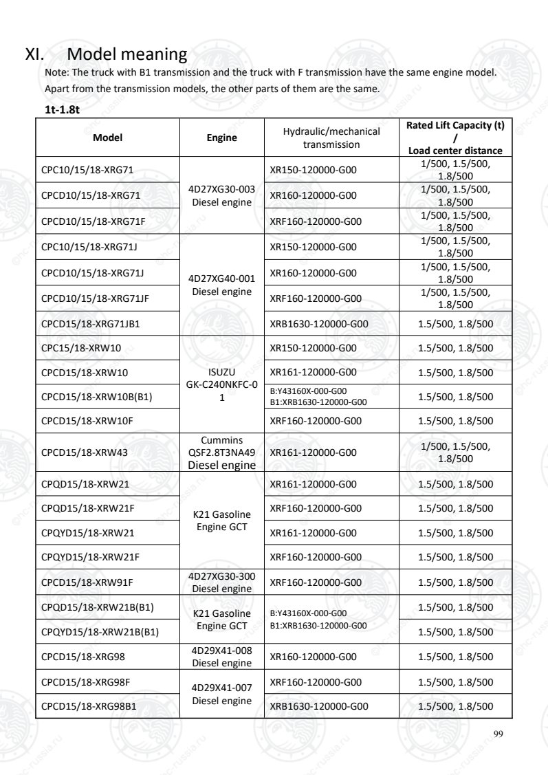
Страница 104
100
Model Engine Hydraulic/mechanical
transmission
Rated Lift Capacity (t)
/
Load center distance
(mm)
RemarksCPCD15/18-XRW32B1 4TNE92-HRJ
Diesel engine
XRB1630-120000-G00 1.5/500, 1.8/500
CPCD15/18-XRW32F XRF160-120000-G01(NEW)
XRF160-120000-G00(OLD) 1.5/500, 1.8/500
CPYD15/18-XRW51B1 K21 LPG XRB1630-120000-G00 1.5/500, 1.8/500
CPCD15/18-XRH5
Cummins
F2.8CS449
Diesel engine
XR161-120000-G00 1.5/500, 1.8/500
Оригинальная страница: таблицы и схемы
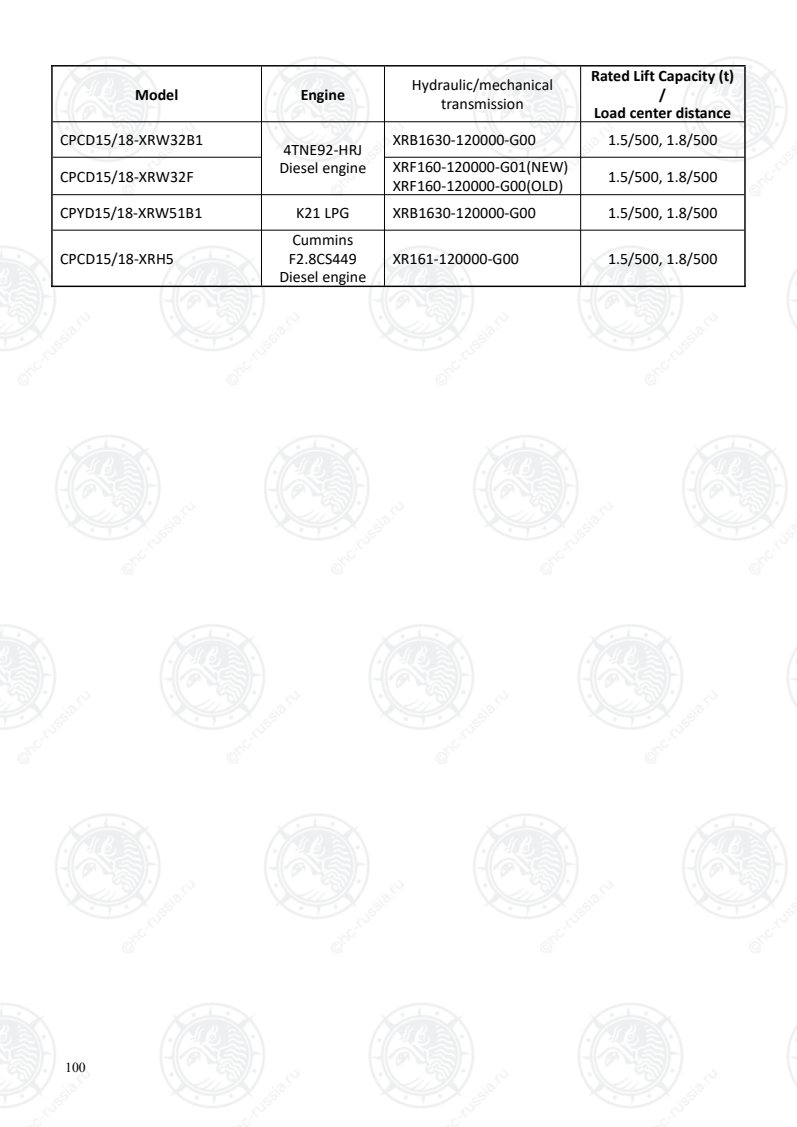
Страница 105
101
2t-2.5t
Model Engine Hydraulic/mechanical
power transmission
Rated Lift Capacity
(t) /
Load center
distance (mm)
RemarksCPC20/25-XRG72
4D32XG30-004
XR250-120000-G00 2/500, 2.5/500
CPCD20/25-XRG72 XR260-120000-G00 2/500, 2.5/500
CPCD20/25-XRG72F XRF260-120000-G01 2/500, 2.5/500
CPC20/25-XRG92
4D32XG40-200
XR250-120000-G00 2/500, 2.5/500
CPCD20/25-XRG92 XR260-120000-G00 2/500, 2.5/500
CPC20/25-XRG72J
4D32XG40-001
XR250-120000-G00 2/500, 2.5/500
CPCD20/25-XRG72J XR260-120000-G00 2/500, 2.5/500
CPCD20/25-XRG72JF
4D32XG40-002
XRF260-120000-G01 2/500, 2.5/500
CPCD20/25-XRG72JB1 XRB2630-120000-G00 2/500, 2.5/500
CPC20/25-XRW10
ISUZU
GK-C240NKFC-01
XR250-120000-G00 2/500, 2.5/500
CPCD20/25-XRW10 XR261-120000-G00 2/500, 2.5/500
CPCD20/25-XRW10B(B1) B:Y43160X-000-G00
B1:XRB2630-120000-G00 2/500, 2.5/500
CPCD20/25-XRW10F XRF260-120000-G01 2/500, 2.5/500
CPCD20/25-XRW43
Cummins
QSF2.8T3NA49
Diesel engine
XR261-120000-G00 2/500, 2.5/500
CPCD20/25-XRW43B Y43160X-000-G00 2/500, 2.5/500
CPCD20/25-XRW43F XRF260-120000-G01 2/500, 2.5/500
CPCD20/25-XRW56
Yanmar
4TNV94L-BXPHZ
Diesel engine
XR261-120000-G00 2/500, 2.5/500
CPCD20/25-XRW56B Y43160X-000-G00 2/500, 2.5/500
CPCD20/25-XRW56F XRF260-120000-G01 2/500, 2.5/500
CPQD20/25-XRW22
K25 Gasoline
Engine GCT
XR261-120000-G00 2/500, 2.5/500
CPQD20/25-XRW22B(B1) B:Y43160X-000-G00
B1:XRB2630-120000-G00 2/500, 2.5/500
CPQD20/25-XRW22F XRF260-120000-G01 2/500, 2.5/500
CPQYD20/25-XRW22 XR261-120000-G00 2/500, 2.5/500
CPQYD20/25-XRW22B(B1) B:Y43160X-000-G00
B1:XRB2630-120000-G00 2/500, 2.5/500
CPQYD20/25-XRW22F XRF260-120000-G01 2/500, 2.5/500
Оригинальная страница: таблицы и схемы
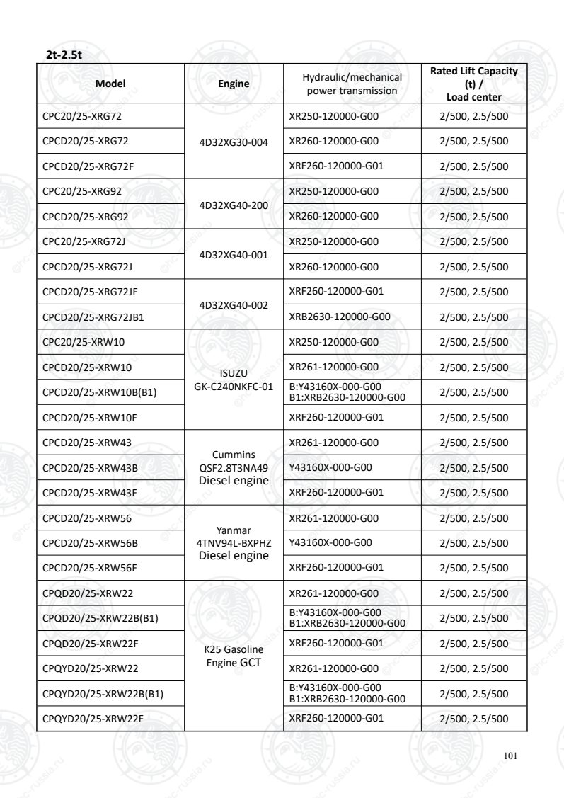
Страница 106
102
Model Engine Hydraulic/mechanical
power transmission
Rated Lift Capacity
(t) /
Load center
distance (mm)
RemarksCPC20/25-XRW55
Mitsubishi S4S
XR250-120000-G00 2/500, 2.5/500
CPCD20/25-XRW55B(B1) B:Y43160X-000-G00
B1:XRB2630-120000-G00 2/500, 2.5/500
CPCD20/25-XRW55F XRF260-120000-G01 2/500, 2.5/500
CPCD20/25-XRW92F 4D32XG30-300 XRF260-120000-G01 2/500, 2.5/500
CPCD20/25-XRW33B(B1)
YANMAR 4TNE98
B:Y43160X-000-G00
B1:XRB2630-120000-G00 2/500, 2.5/500
CPCD20/25-XRW33F XRF260-120000-G01 2/500, 2.5/500
CPQYD20/25-XRW21 GCT K21 LPG XR261-120000-G00 2/500, 2.5/500
CPCD20/25-XRG92F Xinchai
4D32X41-002
XRF260-120000-G01 2/500, 2.5/500
CPCD20/25-XRG92B1 XRB2630-120000-G00 2/500, 2.5/500
CPYD20/25-XRW52F
GCT K25 LPG
XRF260-120000-G01 2/500, 2.5/500
CPYD20/25-XRW52B(B1) B:Y43160X-000-G00
B1:XRB2630-120000-G00 2/500, 2.5/500
CPCD20/25-XRG59 Dachai
CA498-05T3-A250
XR2616-100000-000 2/500, 2.5/500
CPCD20/25-XRG60
Dachai
CA498-06T3R-A24
9
XR2616-100000-000 2/500, 2.5/500
CPCD20/25-XRH5
Cummins
F2.8CS449
Diesel engine
XR261-120000-G00 2/500, 2.5/500
CPCD20/25-XRH5B1 XRB2630-120000-G00 2/500, 2.5/500
CPCD20/25-XRH5F XRF260-120000-G01 2/500, 2.5/500
CPCD20/25-XRG2 C490BPG-416
Diesel engine
XR260-120000-G00 2/500, 2.5/500
Оригинальная страница: таблицы и схемы
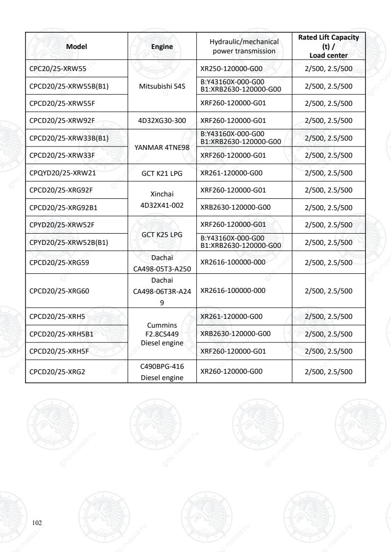
Страница 107
103
3t-3.5t
Model Engine Hydraulic/mechanical
transmission
Rated Lift Capacity
(t) /
Load center
distance (mm)
RemarksCPC30/35/38-XRG72
4D32XG30-004
Diesel engine
XR300-120000-G00 3/500, 3.5/500
3.8/500
CPCD30/35/38-XRG72 XR310-120000-G00 3/500, 3.5/500
3.8/500
CPCD30/35/38-XRG72F XRF310-120000-G01 3/500, 3.5/500
3.8/500
CPC30/35/38-XRG72J 4D32XG40-001
Diesel engine
XR300-120000-G00 3/500, 3.5/500
3.8/500
CPCD30/35/38-XRG72J XR310-120000-G00 3/500, 3.5/500
3.8/500
CPCD30/35/38-XRG72JF 4D32XG40-002
Diesel engine
XRF310-120000-G01 3/500, 3.5/500
3.8/500
CPCD30/35/38-XRG72JB1 XRB3130-120000-G00 3/500, 3.5/500
3.8/500
CPC30/35/38-XRG92
4D32XG40-200
Diesel engine
XR300-120000-G00 3/500, 3.5/500
3.8/500
CPCD30/35/38-XRG92 XR310-120000-G00 3/500, 3.5/500
3.8/500
CPCD30/35/38-XRG92B1 XRB3130-120000-G00 3/500, 3.5/500
3.8/500
CPCD30/35/38-XRG92-GW XR310-120000-G00 3/500, 3.5/500
3.8/500
CPC30-XRW10
ISUZU
GK-C240NKFC-0
1
XR300-120000-G00 3/500
CPCD30-XRW10 XR311-120000-G00 3/500
CPCD30/35-XRW10B(B1) B:Y43160X-000-G00
B1:XRB3130-120000-G00 3/500, 3.5/500
CPCD30-XRW10F XRF310-120000-G01 3/500
CPCD30/35-XRW43
Cummins
QSF2.8T3NA49
Diesel engine
XR311-120000-G00 3/500, 3.5/500
CPCD30/35/38-XRW43B Y43160X-000-G00 3/500, 3.5/500
3.8/500
CPCD30/35/38-XRW43F XRF310-120000-G01 3/500, 3.5/500
3.8/500
CPCD30/35-XRW56
Yanmar
4TNV94L-BXPHZ
Diesel engine
XR311-120000-G00 3/500, 3.5/500
CPCD30/35/38-XRW56B Y43160X-000-G00 3/500, 3.5/500
3.8/500
CPCD30/35/38-XRW56F XRF310-120000-G01 3/500, 3.5/500
3.8/500
CPQD30/35-XRW22
K25 Gasoline
Engine GCT
XR311-120000-G00 3/500, 3.5/500
CPQD30/35/38-XRW22B(B1) B:Y43160X-000-G00
B1:XRB3130-120000-G00
3/500, 3.5/500
3.8/500
CPQD30/35/38-XRW22F XRF310-120000-G01 3/500, 3.5/500
3.8/500
Оригинальная страница: таблицы и схемы
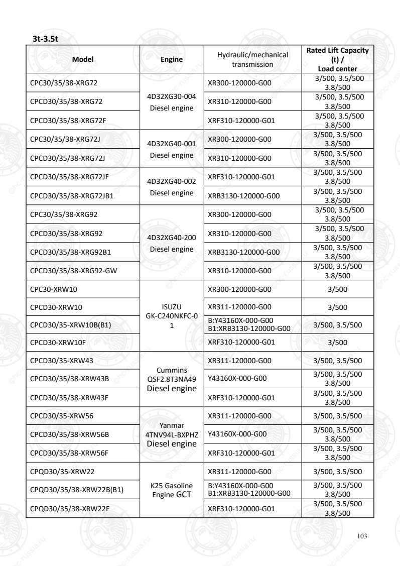
Страница 108
104
Model Engine Hydraulic/mechanical
transmission
Rated Lift Capacity
(t) /
Load center
distance (mm)
RemarksCPQYD30/35/38-XRW22
K25 Gasoline
Engine GCT
XR311-120000-G00 3/500, 3.5/500
3.8/500
CPQYD30/35/38-XRW22B(B1) B:Y43160X-000-G00
B1:XRB3130-120000-G00
3/500, 3.5/500
3.8/500
CPQYD30/35/38-XRW22F XRF310-120000-G01 3/500, 3.5/500
3.8/500
CPCD30/35/38-XRG92F 4D32X41-002
Diesel engine XRF310-120000-G01 3/500, 3.5/500
3.8/500
CPC30/35-XRW55
Mitsubishi
S4S-DPEU2
XR300-120000-G00 3/500, 3.5/500
CPCD30/35-XRW55B(B1) B:Y43160X-000-G00
B1:XRB3130-120000-G00 3/500, 3.5/500
CPCD30/35/38-XRW55F XRF310-120000-G01 3/500, 3.5/500
3.8/500
CPCD30/35/38-XRW92F 4D32XG30-300
Diesel engine XRF310-120000-G01 3/500, 3.5/500
3.8/500
CPCD30/35/38-XRW52F
K25 LPG
XRF310-120000-G01 3/500, 3.5/500
3.8/500
CPCD30/35/38-XRW52B(B1) B:Y43160X-000-G00
B1:XRB3130-120000-G00
3/500, 3.5/500
3.8/500
CPCD30/35-XRG59
Dachai
CA498-05T3-A25
0
XR3116-100000-000 3/500, 3.5/500
CPCD30/35-XRG60
Dachai
CA498-06T3R-A2
49
XR3116-100000-000 3/500, 3.5/500
CPCD30/35/38-XRW33B(B1) YANMAR
4TNE98
B:Y43160X-000-G00
B1:XRB3130-120000-G00 3/500, 3.5/500
CPCD30/35/38-XRW33F XRF310-120000-G01 3.8/500
CPCD30/35/38-XRH5
Cummins
F2.8CS449
Diesel engine
XR311-120000-G00 3/500, 3.5/500
3.8/500
CPCD30/35/38-XRH5B1 XRB3130-120000-G00 3/500, 3.5/500
3.8/500
CPCD30/35/38-XRH5F XRF310-120000-G01 3/500, 3.5/500
3.8/500
CPCD30/35/38-XRG2 C490BPG-416
Diesel engine
XR310-120000-G00 3/500, 3.5/500
3.8/500
Оригинальная страница: таблицы и схемы
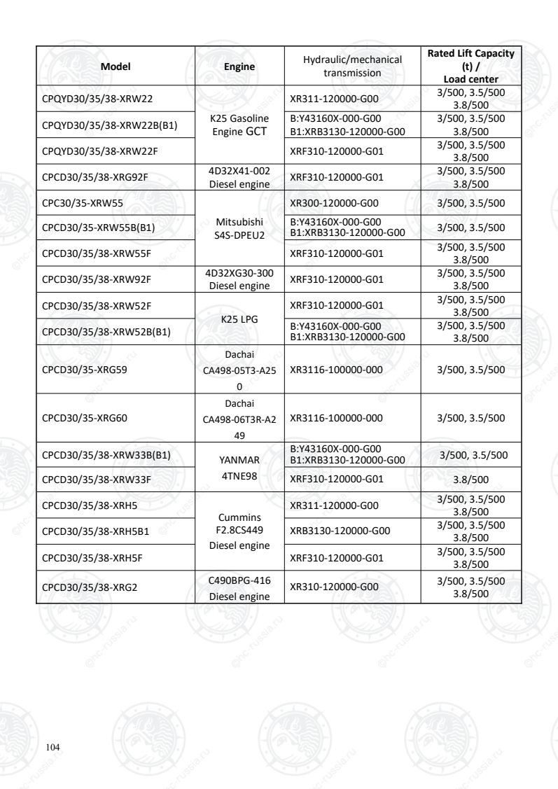
Страница 109
105
4t-X5t
Model Engine Hydraulic/mechanical
transmission
Rated Lift Capacity (t) /
Load center distance
(mm)
RemarksCPCD40/45-XRG76 Yuchai
YC4DK90-T304
XR460-120000-G00
4/500, 4.5/500
CPCD50-XRXG76 5.0/500, 5.5/500
CPCD40/45-XRG75
DCD CY4BG531-2 XR460-120000-G00
4/500, 4.5/500
CPCD50-XRXG75 5.0/500, 5.5/500
CPCD40/45-XRG75-GW 4/500, 4.5/500
CPCD50-XRXG75-GW 5.0/500, 5.5/500
CPCD40/45-XRW34
Perkins 1004D-44T XR463-120000-G00
4/500, 4.5/500
CPCD50-XRXW34 5.0/500, 5.5/500
CPCD40/45-XRW35
Perkins 1004D-44 XR463-120000-G00
4/500, 4.5/500
CPCD50-XRXW35 5.0/500, 5.5/500
CPQYD40/45-XRW57 PSI GM4.3L LX
Dual fuel engine:
XR464-120000-G00
4/500, 4.5/500
CPQYD50-XRXW57 5.0/500, 5.5/500
CPC40/45-XRG73
Xinchai 4D32RG30 XR452-120000-G00
4/500, 4.5/500
CPC50-XRXG73 5.0/500, 5.5/500
CPCD40/45-XRG73
Xinchai 4D32RG30
XR461-120000-G00
4/500, 4.5/500
CPCD50-XRXG73 5.0/500, 5.5/500
CPCD55-XRXG73BN-S XBN458-130000-G01 5.5/500
CPCD40/45-XRW76 Mitsubishi
S6S-G365CSFL
XR463-120000-G00
4/500, 4.5/500
CPCD50-XRXW76 5.0/500
CPCD40/45-XRW76BN Mitsubishi
S6S-G365CSFL
XBN458-130000-G02
4/500, 4.5/500
CPCD50-XRXW76BN 5.0/500
CPCD40/45-XRW19
TD42AA XR467-120000-G00
4/500, 4.5/500
CPCD50-XRXW19 5.0/500
CPCD40/45-XRG93 Xinchai
4D32YG40-001
XR461-120000-G00
4/500, 4.5/500
CPCD50-XRXG93 5.0/500
Оригинальная страница: таблицы и схемы
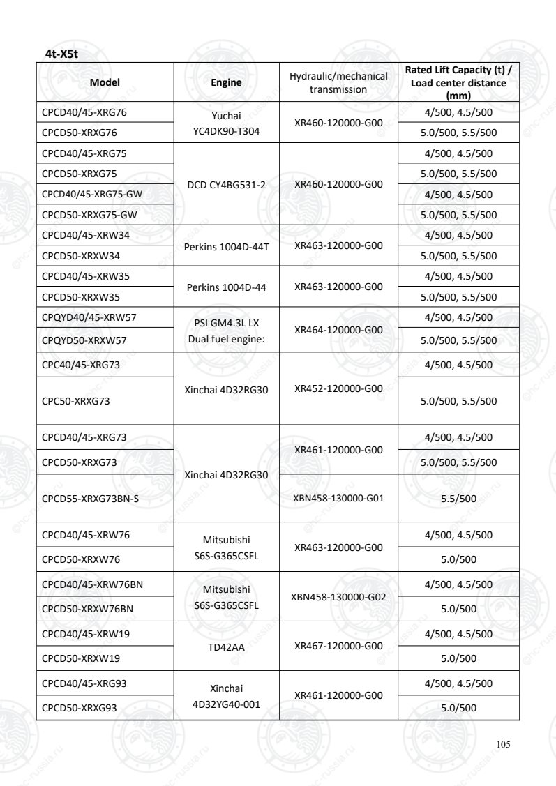
Страница 110
106
Model Engine Hydraulic/mechanical
transmission
Rated Lift Capacity (t) /
Load center distance
(mm)
RemarksCPCD40/45-XRG93-GW 4/500, 4.5/500
CPCD50-XRXG93-GW 5.0/500
CPCD40/45-XRG82
Yuchai
YCF3675-T480
XR461-120000-G00 4/500, 4.5/500
CPCD50-XRXG82 5.0/500
CPCD55-XRXG82BN-S XBN458-130000-G02 5.5/500
CPCD55-XRXG76BN-S Yuchai
YC4DK90-T304
XBN458-130000-G02 5.5/500
Оригинальная страница: таблицы и схемы
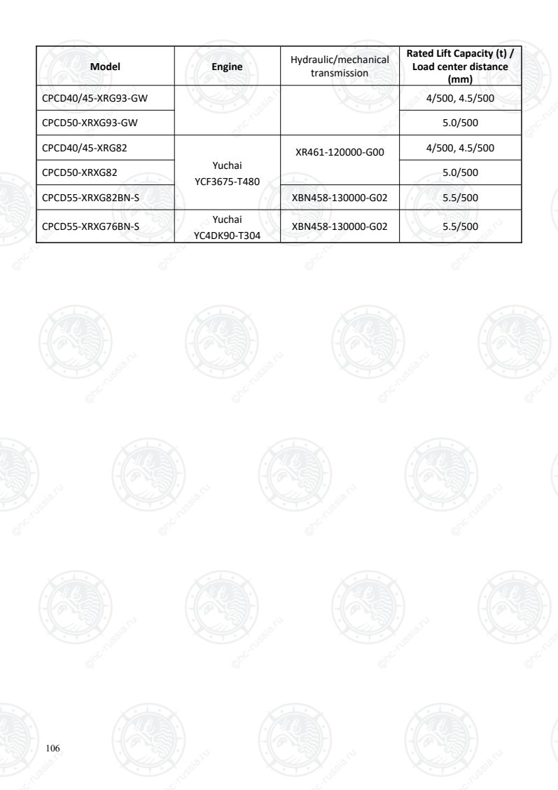
Страница 111
107
XII. Main technical performance parameters
1.0-1.8t
Model CPCD10-XRG71 CPC15-XRG71
CPCD15-XRG71
CPC18-XRG71
CPCD18-XRG71
Rated load capacity
kg 1000 1500 1750
Load center distance
mm 500 500 500
Max. lift height mm 3000 3000 3000
Free lift height mm 155 155 155
Max. lift speed, full
load
mm/s
460 580 580
Tilt angle of mast,
forward/backward
(°)
6°/12° 6°/12° 6°/12°
Max. running speed,
no load
km/h
17.5 17.5 17.5
Min. ground
clearance, mm 115 115 115
Min. outside steering
radius
mm
2035 2035 2060
Max. gradeability,
full load
%
18 18 18
Wheelbase
mm 1475 1475 1475
Wheel track
(front/rear)
mm
890/920 890/920 890/920
Weight kg 2720 2720 2880
Dimensions
(including forks)
(L×W×H)
3205×1090×2120 3205×1090×2120 3240×1090×2120
Tires (front/rear) 6.5-10-10PR/2
5.00-8-8PR/2
6.5-10-10PR/2
5.00-8-10PR/2
6.5-10-10PR/2
5.00-8-8PR/2
Voltage (V) /
Capacitance (Ah) 12/60 12/60 12/60
Dieselengineoil
Model 4D27XG30-003
Rated
power/rpm 34kW/2500 r/min
Max.
torque/rpm 140N·m / (1000-1800) r/min
Displacement
(L) 2.670
Оригинальная страница: таблицы и схемы
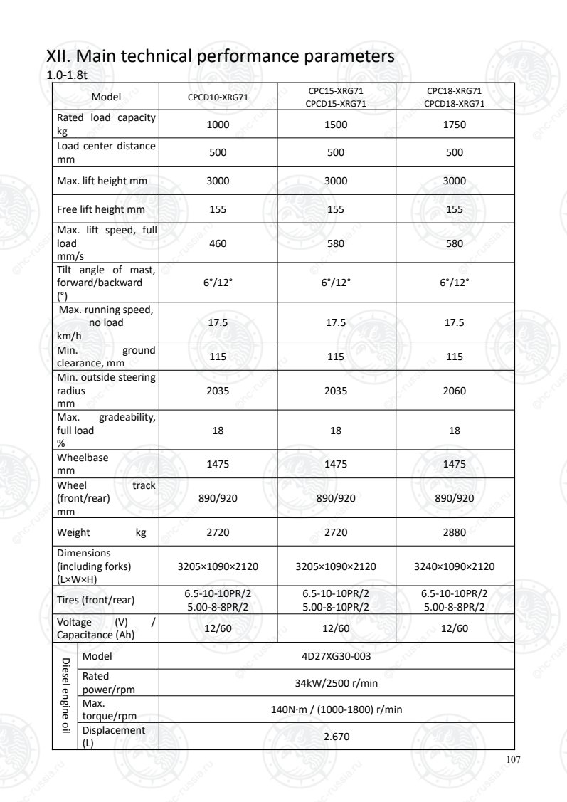
Страница 112
108
Model CPCD15-XRG71F CPCD18-XRG71F
Rated load capacity
kg 1500 1750
Load center distance
mm 500 500
Max. lift height mm 3000 3000
Free lift height mm 155 155
Max. lift speed, full
load
mm/s
580 580
Tilt angle of mast,
forward/backward
(°)
6°/12° 6°/12°
Max. running speed,
no load
km/h
17.5 17.5
Min. ground
clearance, mm 115 115
Min. outside steering
radius
mm
2035 2060
Max. gradeability,
full load
%
25 25
Wheelbase
mm 1475 1475
Wheel track
(front/rear)
mm
890/920 890/920
Weight kg 2720 2880
Dimensions
(including forks)
(L×W×H)
3205×1090×2120 3240×1090×2120
Tires (front/rear) 6.5-10-10PR/2
5.00-8-10PR/2
6.5-10-10PR/2
5.00-8-10PR/2
Voltage (V) /
Capacitance (Ah) 12/60 12/60
Dieselengineoil
Model 4D27XG30-008
Rated
power/rpm 34kW/2500 r/min
Max.
torque/rpm 140N·m / (1000-1800) r/min
Displacement
(L) 2.670
Оригинальная страница: таблицы и схемы
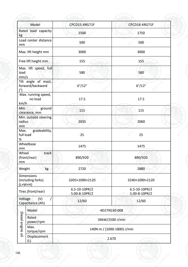
Страница 113
109
Model CPC15-XRG91 CPCD15-XRG91 CPC18-XRG91 CPCD18-XRG91
Rated load capacity
kg 1500 1500 1750 1750
Load center distance
mm 500 500 500 500
Max. lift height mm 3000 3000 3000 3000
Free lift height mm 155 155 155 155
Max. lift speed, full
load
mm/s
580 580 580 580
Tilt angle of mast,
forward/backward 6°/12° 6°/12° 6°/12° 6°/12°
Max. running speed,
no load
km/h
17.5 17.5 17.5 17.5
Min. ground
clearance, mm 105 115 105 115
Min. outside steering
radius
mm
2035 2035 2060 2060
Max. gradeability, full
load
%
20 25 20 25
Wheelbase
mm 1475 1475 1475 1475
Wheel track
(front/rear)
mm
890/920 890/920 890/920 890/920
Weight kg 2720 2720 2880 2880
Dimensions
(including forks)
(L×W×H)
3205×1090×2120 3205×1090×2120 3235×1090×2120 3240×1090×2120
Tires (front/rear) 6.5-10-10PR/2
5.00-8-10PR/2
6.5-10-10PR/2
5.00-8-10PR/2
6.5-10-10PR/2
5.00-8-10PR/2
6.5-10-10PR/2
5.00-8-10PR/2
Voltage (V) /
Capacitance (Ah) 12/90 12/90 12/90 12/90
Dieselengine
Model 4D27XG40-201
Rated
power/rpm 34kW/2500 r/min
Max.
torque/rpm 140N·m / (1000-1800) r/min
Displacement
(L) 2.670
Оригинальная страница: таблицы и схемы
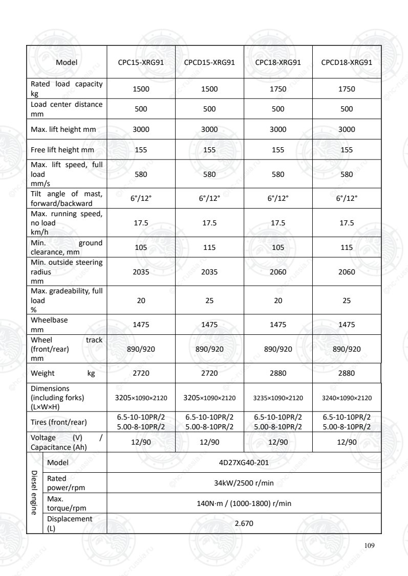
Страница 114
110
Model CPCD15-XRG71JF
CPCD15-XRG71JB1
CPCD18-XRG71JF
CPCD18-XRG71JB1
Rated load capacity
kg 1500 1750
Load center distance
mm 500 500
Max. lift height mm 3000 3000
Free lift height mm 155 155
Max. lift speed, full
load
mm/s
580 580
Tilt angle of mast,
forward/backward
(°)
6°/12° 6°/12°
Max. running speed,
no load
km/h
17.5 17.5
Min. ground
clearance, mm 115 115
Min. outside steering
radius
mm
2035 2060
Max. gradeability,
full load
%
25 25
Wheelbase
mm 1475 1475
Wheel track
(front/rear)
mm
890/920 890/920
Weight kg 2720 2880
Dimensions
(including forks)
(L×W×H)
3205×1090×2120 3240×1090×2120
Tires (front/rear) 6.5-10-10PR/2
5.00-8-10PR/2
6.5-10-10PR/2
5.00-8-10PR/2
Voltage (V) /
Capacitance (Ah) 12/60 12/60
Dieselengineoil
Model 4D27XG40-002
Rated
power/rpm 34kW/2500 r/min
Max.
torque/rpm 140N·m / (1000-1800) r/min
Displacement
(L) 2.670
Оригинальная страница: таблицы и схемы
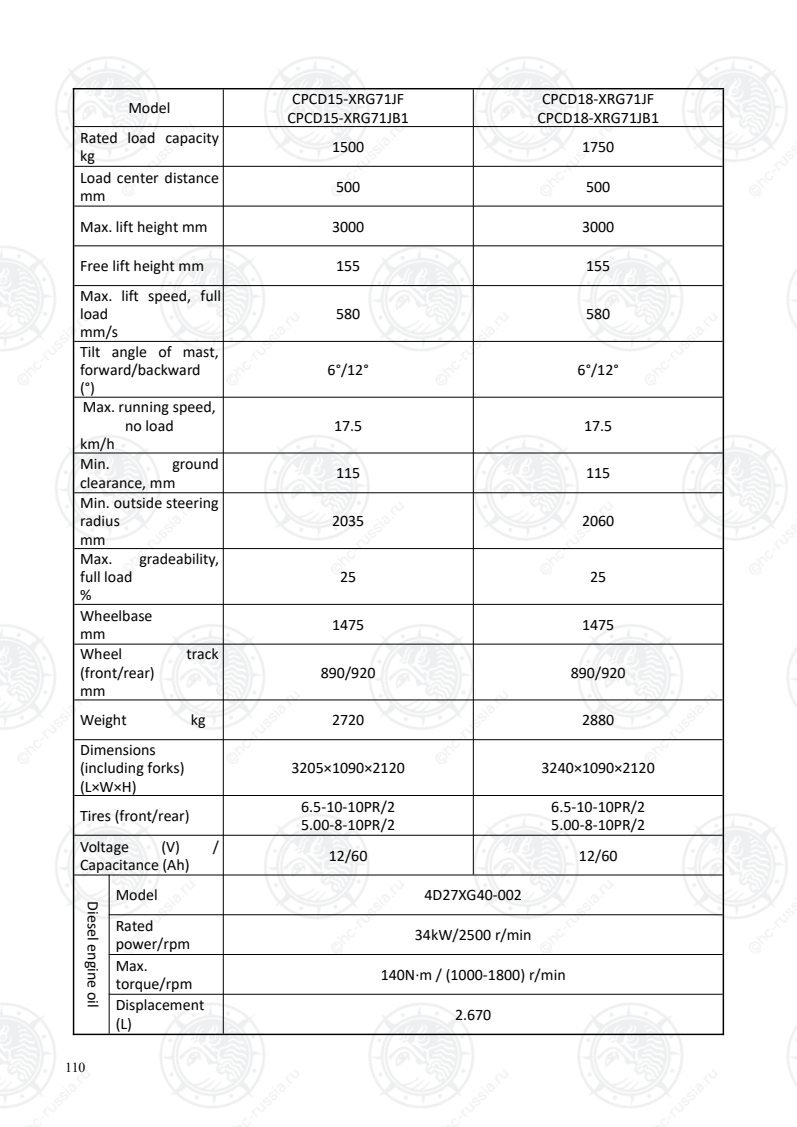
Страница 115
111
Model CPC15-XRW10
CPCD15-XRW10
CPC18-XRW10
CPCD18-XRW10
Rated load capacity
kg 1500 1750
Load center distance
mm 500 500
Max. lift height mm 3000 3000
Free lift height mm 155 155
Max. lift speed, full
load
mm/s
610 610
Tilt angle of mast,
forward/backward
(°)
6°/12° 6°/12°
Max. running speed,
no load
km/h
17.5 17.5
Min. ground
clearance, mm 115 115
Min. outside steering
radius
mm
2035 2060
Max. gradeability,
full load
%
25 25
Wheelbase
mm 1475 1475
Wheel track
(front/rear)
mm
890/920 890/920
Weight kg 2720 2880
Dimensions
(including forks)
(L×W×H)
3205×1090×2120 3240×1090×2120
Tires (front/rear) 6.5-10-10PR/2
5.00-8-10PR/2
6.5-10-10PR/2
5.00-8-8PR/2
Voltage (V) /
Capacitance (Ah) 12/60 12/60
Dieselengineoil
Model ISUZU GK-C240NKFC-01
Rated
power/rpm 35.4kW/2500r/min
Max.
torque/rpm 139.9N·m/ 1800 r/min
Displacement
(L) 2.369
Оригинальная страница: таблицы и схемы
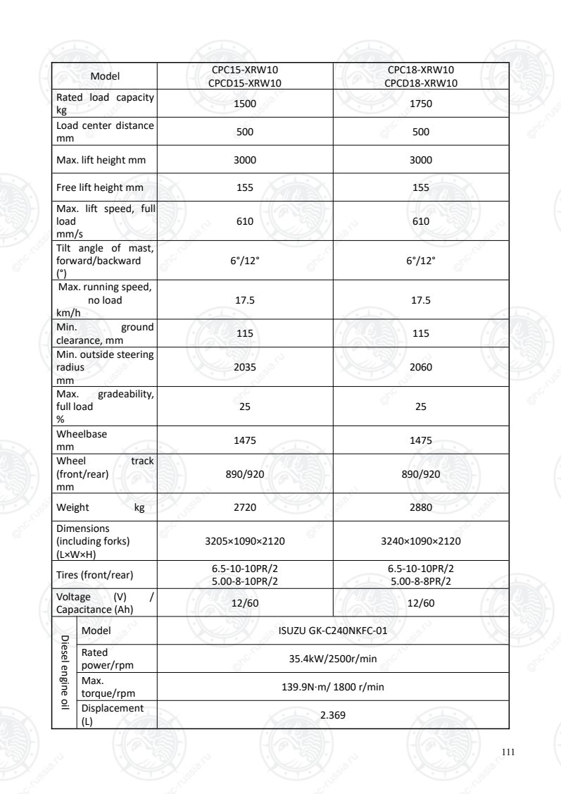
Страница 116
112
Model CPCD10-XRW43 CPCD15-XRW43 CPCD18-XRW43
Rated load capacity
kg 1000 1500 1750
Load center distance
mm 500 500 500
Max. lift height mm 3000 3000 3000
Free lift height mm 155 155 155
Max. lift speed, full
load
mm/s
500 500 500
Tilt angle of mast,
forward/backward
(°)
6°/12° 6°/12° 6°/12°
Max. running speed,
no load
km/h
17.5 17.5 17.5
Min. ground
clearance, mm 105 105 105
Min. outside steering
radius
mm
2000 2000 2030
Max. gradeability,
full load
%
20 20 20
Wheelbase
mm 1475 1475 1475
Wheel track
(front/rear)
mm
890/920 890/920 890/920
Weight kg 2510 2660 2785
Dimensions
(including forks)
(L×W×H)
3205×1090×2120 3205×1090×2120 3240×1090×2120
Tires (front/rear) 6.5-10-10PR/2
5.00-8-10PR/2
6.5-10-10PR/2
5.00-8-10PR/2
6.5-10-10PR/2
5.00-8-8PR/2
Voltage (V) /
Capacitance (Ah) 12/60 12/60 12/60
Dieselengineoil
Model Cummins QSF2.8T3NA49
Rated
power/rpm 36kW/2500r/min
Max.
torque/rpm 186N·m/ 1500 r/min
Displacement
(L) 2.8
Оригинальная страница: таблицы и схемы
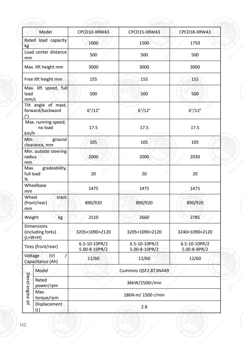
Страница 117
113
Model CPCD15-XRW32F
CPCD15-XRW32B1
CPCD18-XRW32F
CPCD15-XRW32B1
Rated load capacity
kg 1500 1750
Load center distance
mm 500 500
Max. lift height mm 3000 3000
Free lift height mm 155 155
Max. lift speed, full
load
mm/s
580 580
Tilt angle of mast,
forward/backward
(°)
6°/12° 6°/12°
Max. running speed,
no load
km/h
19 19
Min. ground
clearance, mm 115 115
Min. outside steering
radius
mm
2035 2060
Max. gradeability,
full load
%
25 25
Wheelbase
mm 1475 1475
Wheel track
(front/rear)
mm
890/920 890/920
Weight kg 2720 2880
Dimensions
(including forks)
(L×W×H)
3205×1090×2120 3240×1090×2120
Tires (front/rear) 6.5-10-10PR/2
5.00-8-10PR/2
6.5-10-10PR/2
5.00-8-8PR/2
Voltage (V) /
Capacitance (Ah) 12/90 12/90
Dieselengine
Model 4TNE92-HRJ
Rated
power/rpm 32.8kW/2450 r/min
Max.
torque/rpm 142N·m/1600 r/min
Displacement
(L) 2.659
Оригинальная страница: таблицы и схемы
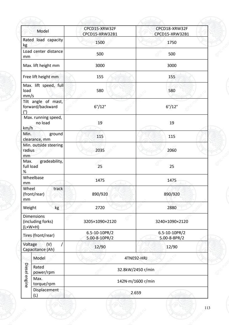
Страница 118
114
Model CPCD15-XRW32B CPCD18-XRW32B
Rated load capacity
kg 1500 1750
Load center distance
mm 500 500
Max. lift height mm 3000 3000
Free lift height mm 155 155
Max. lift speed, full
load
mm/s
580 580
Tilt angle of mast,
forward/backward
(°)
6°/12° 6°/12°
Max. running speed,
no load
km/h
19.3 19.3
Min. ground
clearance, mm 115 115
Min. outside steering
radius
mm
2035 2060
Max. gradeability,
full load
%
25 25
Wheelbase
mm 1475 1475
Wheel track
(front/rear)
mm
890/920 890/920
Weight kg 2720 2880
Dimensions
(including forks)
(L×W×H)
3205×1090×2120 3240×1090×2120
Tires (front/rear) 6.5-10-10PR/2
5.00-8-10PR/2
6.5-10-10PR/2
5.00-8-8PR/2
Voltage (V) /
Capacitance (Ah) 12/90 12/90
Dieselengine
Model 4TNE92-HRJ
Rated
power/rpm 32.8kW/2450 r/min
Max.
torque/rpm 142N·m/1600 r/min
Displacement
(L) 2.659
Оригинальная страница: таблицы и схемы
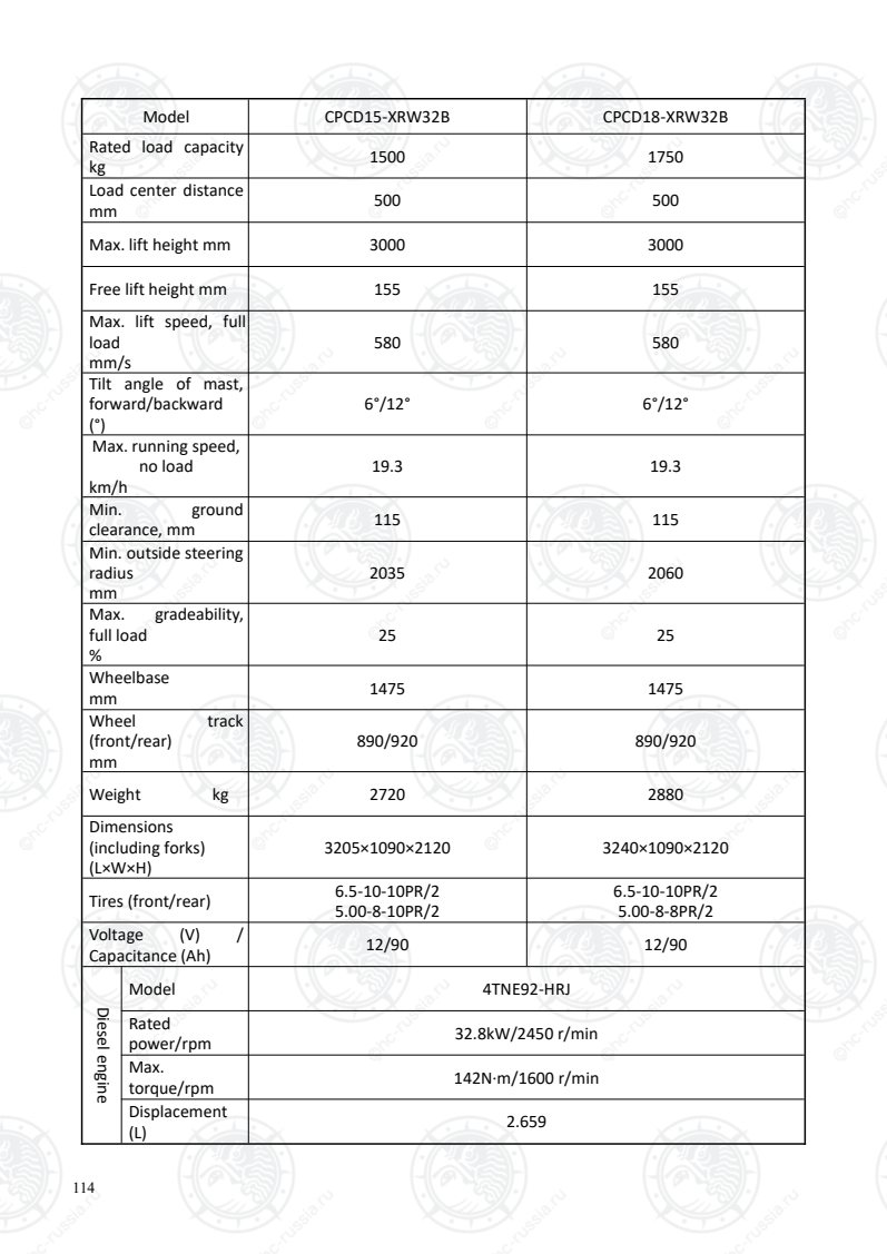
Страница 119
115
Model CPQD15-XRW21 CPQD18-XRW21
Rated load capacity
kg 1500 1750
Load center distance
mm 500 500
Max. lift height mm 3000 3000
Free lift height mm 155 155
Max. lift speed, full
load
mm/s
500 500
Tilt angle of mast,
forward/backward
(°)
6°/12° 6°/12°
Max. running speed,
no load
km/h
17.5 17.5
Min. ground
clearance, mm 115 115
Min. outside steering
radius
mm
2035 2060
Max. gradeability,
full load
%
20 20
Wheelbase
mm 1475 1475
Wheel track
(front/rear)
mm
890/920 890/920
Weight kg 2720 2880
Dimensions
(including forks)
(L×W×H)
3205×1090×2120 3240×1090×2120
Tires (front/rear) 6.5-10-10PR/2
5.00-8-10PR/2
6.5-10-10PR/2
5.00-8-8PR/2
Voltage (V) /
Capacitance (Ah) 12/60 12/60
Gasolineengines
Model GCT K21
Rated
power/rpm 31.2kW/2250 r/min
Max.
torque/rpm 143.7N·m/1600 r/min
Displacement
(L) 2.065
Power type Gasoline
Оригинальная страница: таблицы и схемы
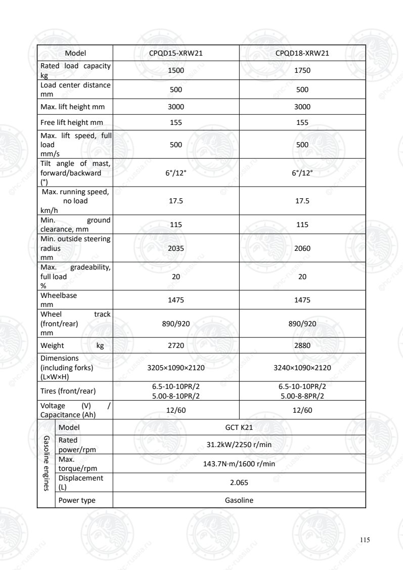
Страница 120
116
Model CPQD15-XRW21B
CPQD15-XRW21B1
CPQD18-XRW21B
CPQD18-XRW21B1
Rated load capacity
kg 1500 1750
Load center distance
mm 500 500
Max. lift height mm 3000 3000
Free lift height mm 155 155
Max. lift speed, full
load
mm/s
510 510
Tilt angle of mast,
forward/backward
(°)
6°/12° 6°/12°
Max. running speed,
no load
km/h
18 18
Min. ground
clearance, mm 115 115
Min. outside steering
radius
mm
2035 2060
Max. gradeability,
full load
%
20 20
Wheelbase
mm 1475 1475
Wheel track
(front/rear)
mm
890/920 890/920
Weight kg 2720 2880
Dimensions
(including forks)
(L×W×H)
3205×1090×2120 3240×1090×2120
Tires (front/rear) 6.5-10-10PR/2
5.00-8-10PR/2
6.5-10-10PR/2
5.00-8-8PR/2
Voltage (V) /
Capacitance (Ah) 12/60 12/60
Gasolineengines
Model GCT GK21
Rated
power/rpm 31.2kW/2250 r/min
Max.
torque/rpm 143.7N·m/1600 r/min
Displacement
(L) 2.065
Power type Gasoline
Оригинальная страница: таблицы и схемы
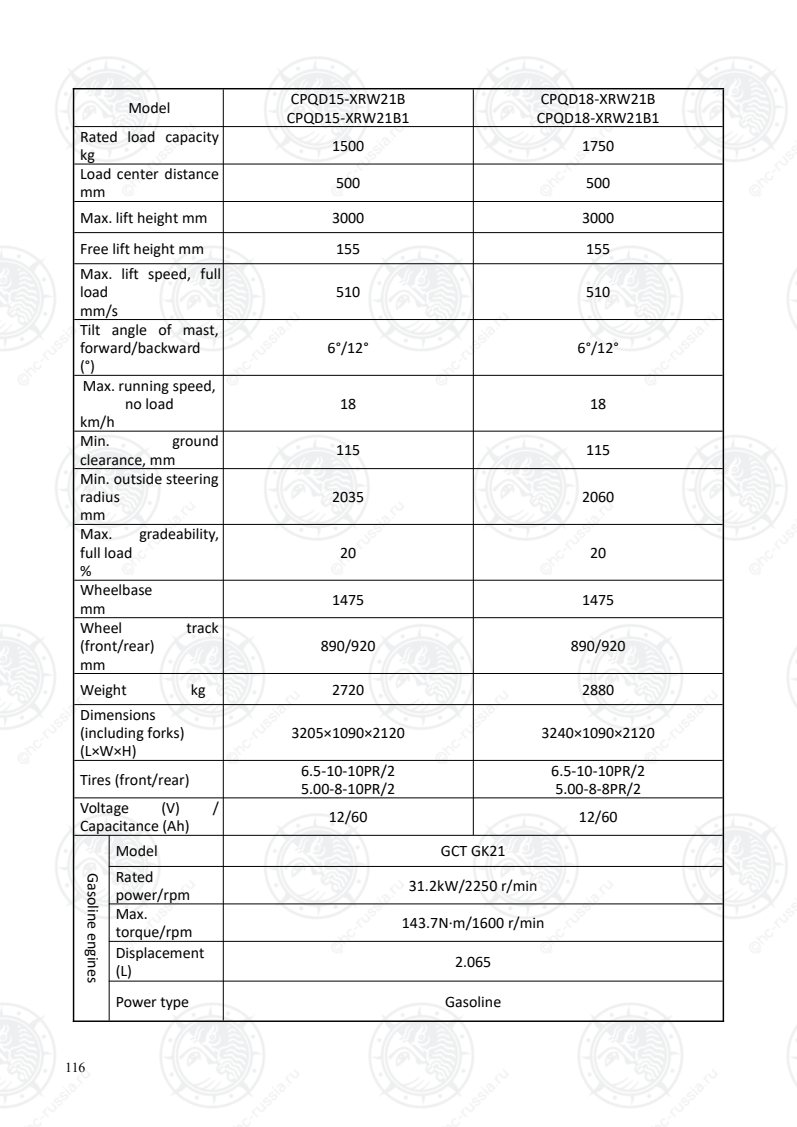
Страница 121
117
Model CPQYD15-XRW21B
CPQYD15-XRW21B1
CPQYD18-XRW21B
CPQYD18-XRW21B1
Rated load capacity
kg 1500 1750
Load center distance
mm 500 500
Max. lift height mm 3000 3000
Free lift height mm 155 155
Max. lift speed, full
load
mm/s
510 510
Tilt angle of mast,
forward/backward
(°)
6°/12° 6°/12°
Max. running speed,
no load
km/h
18 18
Min. ground
clearance, mm 115 115
Min. outside steering
radius
mm
2035 2060
Max. gradeability,
full load
%
20 20
Wheelbase
mm 1475 1475
Wheel track
(front/rear)
mm
890/920 890/920
Weight kg 2720 2880
Dimensions
(including forks)
(L×W×H)
3205×1090×2120 3240×1090×2120
Tires (front/rear) 6.5-10-10PR/2
5.00-8-10PR/2
6.5-10-10PR/2
5.00-8-8PR/2
Voltage (V) /
Capacitance (Ah) 12/60 12/60
Gasolineengines
Model GCT GK21
Rated
power/rpm 31.2kW/2250 r/min
Max.
torque/rpm 143.7N·m/1600 r/min
Displacement
(L) 2.065
Оригинальная страница: таблицы и схемы
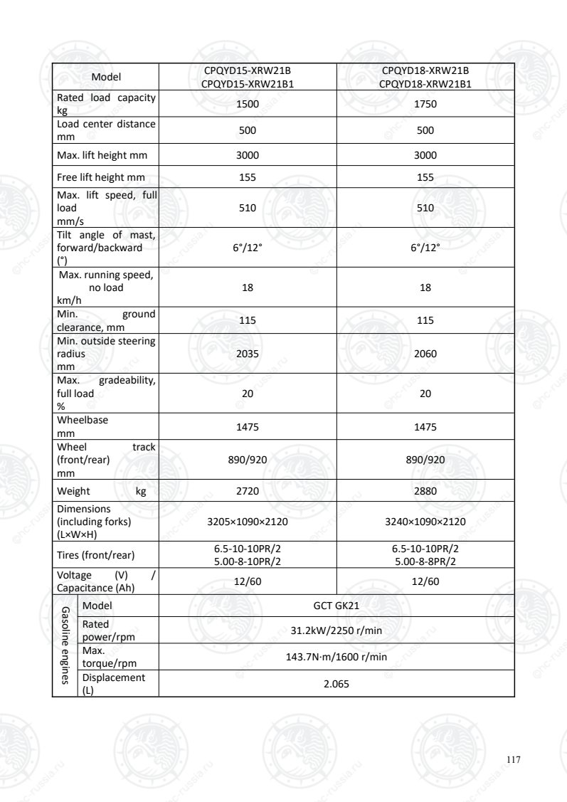
Страница 122
118
Model CPCD15-XRW91F CPCD18-XRW91F
Rated load capacity
kg 1500 1750
Load center distance
mm 500 500
Max. lift height mm 3000 3000
Free lift height mm 155 155
Max. lift speed, full
load
mm/s
580 580
Tilt angle of mast,
forward/backward
(°)
6°/12° 6°/12°
Max. running speed,
no load
km/h
17.5 17.5
Min. ground
clearance, mm 115 115
Min. outside steering
radius
mm
2035 2060
Max. gradeability,
full load
%
25 25
Wheelbase
mm 1475 1475
Wheel track
(front/rear)
mm
890/920 890/920
Weight kg 2720 2880
Dimensions
(including forks)
(L×W×H)
3205×1090×2120 3240×1090×2120
Tires (front/rear) 6.5-10-10PR/2
5.00-8-10PR/2
6.5-10-10PR/2
5.00-8-8PR/2
Voltage (V) /
Capacitance (Ah) 12/60 12/60
Gasolineengines
Model 4D27XG30-300
Rated
power/rpm 34kW/2500 r/min
Max.
torque/rpm 140N·m/(1600-1800) r/min
Displacement
(L) 2.670
Оригинальная страница: таблицы и схемы
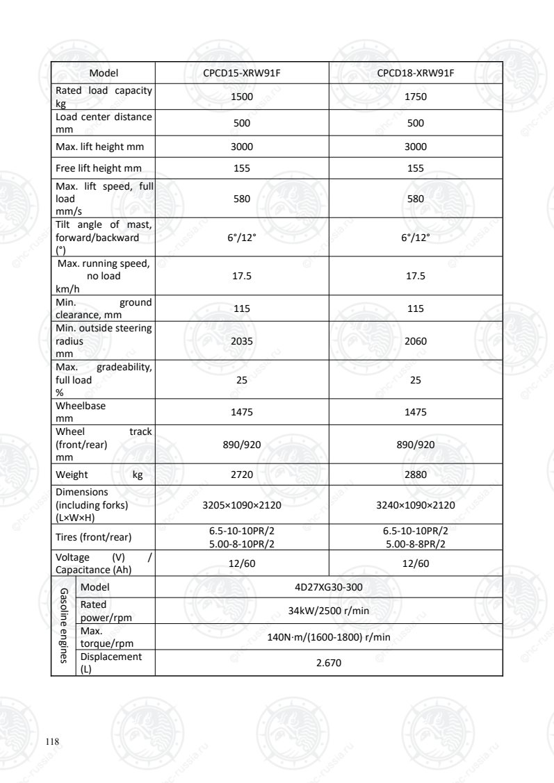
Страница 123
119
Model CPCD15-XRG98 CPCD18-XRG98
Rated load capacity
kg 1500 1750
Load center distance
mm 500 500
Max. lift height mm 3000 3000
Free lift height mm 155 155
Max. lift speed, full
load
mm/s
580 580
Tilt angle of mast,
forward/backward
(°)
6°/12° 6°/12°
Max. running speed,
no load
km/h
17.5 17.5
Min. ground
clearance, mm 115 115
Min. outside steering
radius
mm
2035 2060
Max. gradeability,
full load
%
25 25
Wheelbase
mm 1475 1475
Wheel track
(front/rear)
mm
890/920 890/920
Weight kg 2720 2880
Dimensions
(including forks)
(L×W×H)
3205×1090×2120 3240×1090×2120
Tires (front/rear) 6.5-10-10PR/2
5.00-8-10PR/2
6.5-10-10PR/2
5.00-8-8PR/2
Voltage (V) /
Capacitance (Ah) 12/90 12/90
Dieselengine
Model 4D29X41-008
Rated
power/rpm 34kW/2500 r/min
Max.
torque/rpm 150N·m/1600 r/min-1800 r/min
Emission
standards China IV
Оригинальная страница: таблицы и схемы
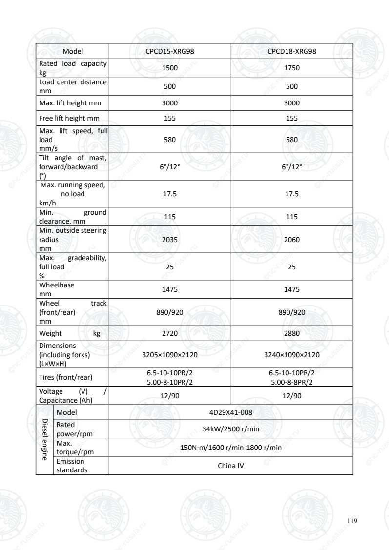
Страница 124
120
Model CPCD15-XRG98F
CPCD15-XRG98B1
CPCD18-XRG98F
CPCD18-XRG98B1
Rated load capacity
kg 1500 1750
Load center distance
mm 500 500
Max. lift height mm 3000 3000
Free lift height mm 155 155
Max. lift speed, full
load
mm/s
580 580
Tilt angle of mast,
forward/backward
(°)
6°/12° 6°/12°
Max. running speed,
no load
km/h
17.5 17.5
Min. ground
clearance, mm 115 115
Min. outside steering
radius
mm
2035 2060
Max. gradeability,
full load
%
25 25
Wheelbase
mm 1475 1475
Wheel track
(front/rear)
mm
890/920 890/920
Weight kg 2720 2880
Dimensions
(including forks)
(L×W×H)
3205×1090×2120 3240×1090×2120
Tires (front/rear) 6.5-10-10PR/2
5.00-8-10PR/2
6.5-10-10PR/2
5.00-8-8PR/2
Voltage (V) /
Capacitance (Ah) 12/90 12/90
Dieselengine
Model 4D29X41-007
Rated
power/rpm 34kW/2500 r/min
Max.
torque/rpm 150N·m/1600 r/min-1800 r/min
Emission
standards China IV
Оригинальная страница: таблицы и схемы
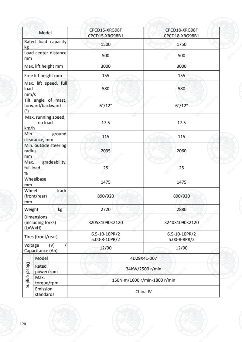
Страница 125
121
Model CPCD15-XRH5 CPCD18-XRH5
Rated load capacity
kg 1500 1750
Load center distance
mm 500 500
Max. lift height mm 3000 3000
Free lift height mm 155 155
Max. lift speed, full
load
mm/s
500 500
Tilt angle of mast,
forward/backward
(°)
6°/12° 6°/12°
Max. running speed,
no load
km/h
17.5 17.5
Min. ground
clearance, mm 105 105
Min. outside steering
radius
mm
2000 2030
Max. gradeability,
full load
%
20 20
Wheelbase
mm 1475 1475
Wheel track
(front/rear)
mm
890/920 890/920
Weight kg 2650 2785
Dimensions
(including forks)
(L×W×H)
3205×1090×2120 3235×1090×2120
Tires (front/rear) 6.5-10-10PR/2
5.00-8-10PR/2
6.5-10-10PR/2
5.00-8-8PR/2
Voltage (V) /
Capacitance (Ah) 12/90 12/90
Dieselengine
Model F2.8CS449
Rated
power/rpm 36kW/2500 r/min
Max.
torque/rpm 186N·m/ 1500 r/min
Emission
standards China IV
Оригинальная страница: таблицы и схемы
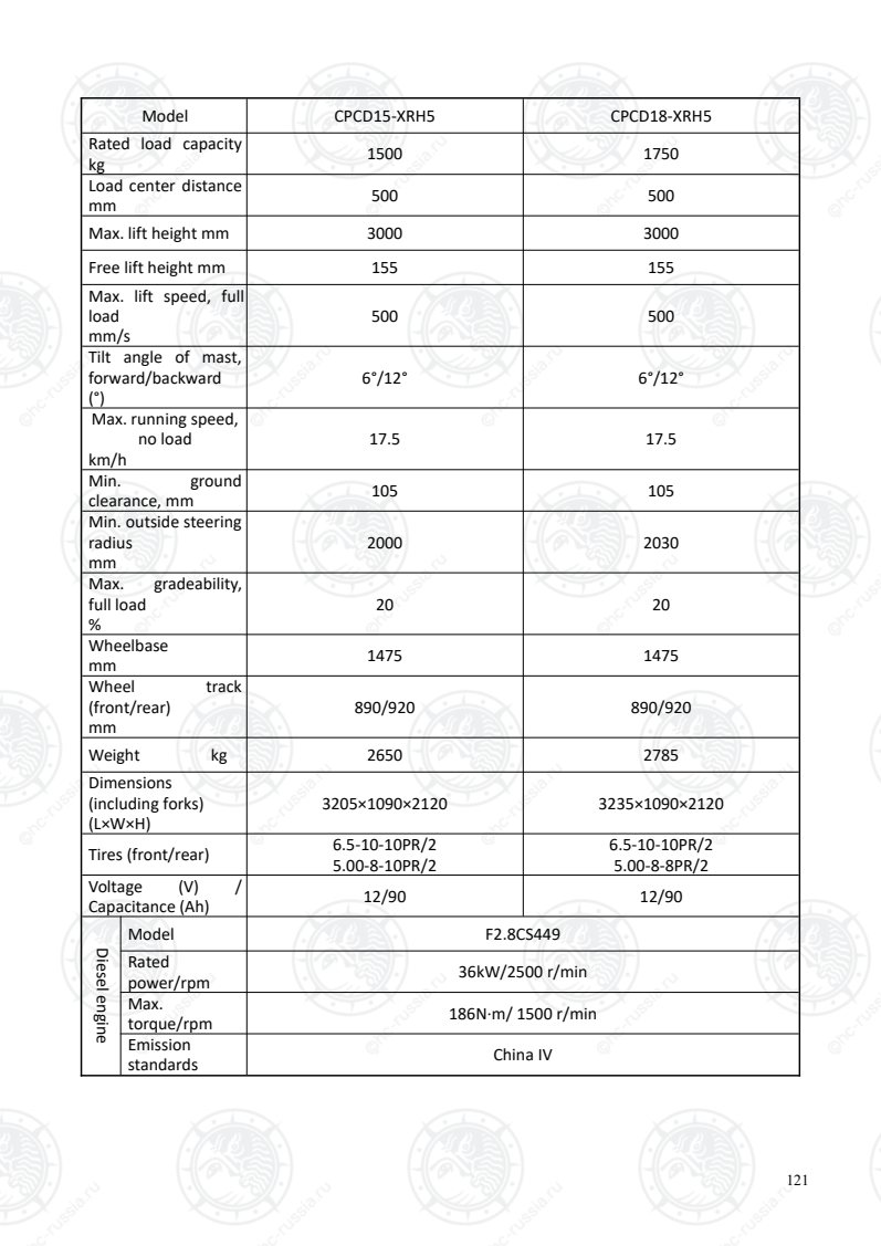
Страница 126
122
2-3.8t
Model CPC20-XRG72
CPCD20-XRG72
CPC25-XRG72
CPCD25-XRG72
CPC30-XRG72
CPCD30-XRG72
CPC35-XRG72
CPCD35-XRG72
Rated load capacity
kg 2000 2500 3000 3500
Load center distance
mm 500 500 500 500
Max. lift height mm 3000 3000 3000 3000
Free lift height mm 160 160 165 170
Max. lift speed, full
load
mm/s
620 620 490 430
Tilt angle of mast,
forward/backward 6°/12° 6°/12° 6°/12° 6°/12°
Max. running speed,
no load
km/h
21 21 19 19
Min. ground
clearance, mm 105 105 130 130
Min. outside steering
radius
mm
2270 2330 2400 2440
Max. gradeability, full
load
%
25 25 25 20
Wheelbase
mm 1650 1650 1700 1700
Wheel track
(front/rear)
mm
965/973 965/975 1005/975 1005/975
Weight kg 3450 3850 4380 4750
Dimensions
(including forks)
(L×W×H)
3610×1155×2120 3680×1155×2120 3770×1225×2150 3850×1225×2150
Tires (front/rear) 7.00-12-12PR/2
6.00-9-10PR/2
7.00-12-12PR/2
6.00-9-10PR/2
28×9-15-14PR/2
6.50-10-10PR/2
28×9-15-14PR/2
6.50-10-10PR/2
Voltage (V) /
Capacitance (Ah) 12/90 12/90 12/90 12/90
Dieselengine
Model 4D32XG30-004
Rated
power/rpm 45kW/2500 r/min
Max.
torque/rpm 200N·m / (1500-1800) r/min
Displacement
(L) 3.168
Оригинальная страница: таблицы и схемы
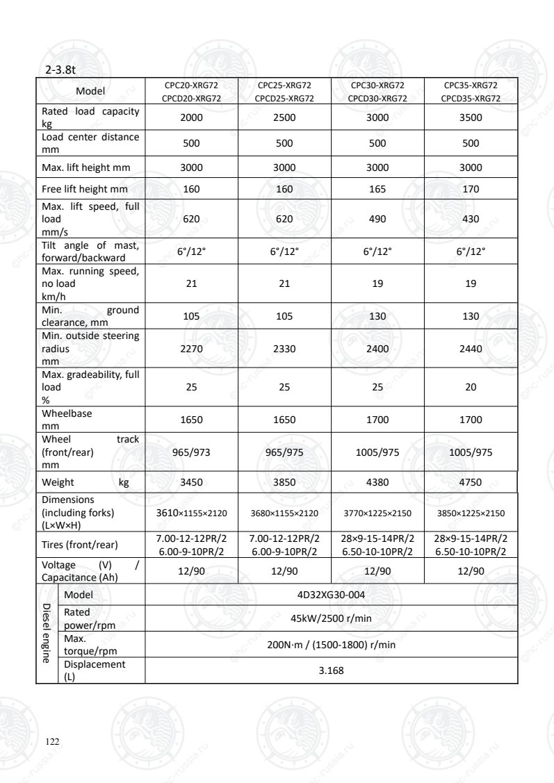
Страница 127
123
Model CPC20-XRG92
CPCD20-XRG92
CPC25-XRG92
CPCD25-XRG92
CPC30-XRG92
CPCD30-XRG92
CPC35-XRG92
CPCD35-XRG92
Rated load capacity
kg 2000 2500 3000 3500
Load center distance
mm 500 500 500 500
Max. lift height mm 3000 3000 3000 3000
Free lift height mm 160 160 165 170
Max. lift speed, full
load
mm/s
620 620 490 430
Tilt angle of mast,
forward/backward 6°/12° 6°/12° 6°/12° 6°/12°
Max. running speed,
no load
km/h
21 21 19 19
Min. ground
clearance, mm 105 105 130 130
Min. outside steering
radius
mm
2270 2330 2400 2450
Max. gradeability, full
load
%
25 25 25 20
Wheelbase
mm 1650 1650 1700 1700
Wheel track
(front/rear)
mm
965/973 965/975 1005/975 1005/975
Weight kg 3450 3850 4380 4750
Dimensions
(including forks)
(L×W×H)
3615×1155×2120 3680×1155×2120 3770×1225×2150 3850×1225×2150
Tires (front/rear) 7.00-12-12PR/2
6.00-9-10PR/2
7.00-12-12PR/2
6.00-9-10PR/2
28×9-15-14PR/2
6.50-10-10PR/2
28×9-15-14PR/2
6.50-10-10PR/2
Voltage (V) /
Capacitance (Ah) 12/90 12/90 12/90 12/90
Dieselengine
Model 4D32X41-001
Rated
power/rpm 36.8kW/2500 r/min
Max.
torque/rpm 200N·m / (1400-1600) r/min
Displacement
(L) 3.168 China IV
Оригинальная страница: таблицы и схемы
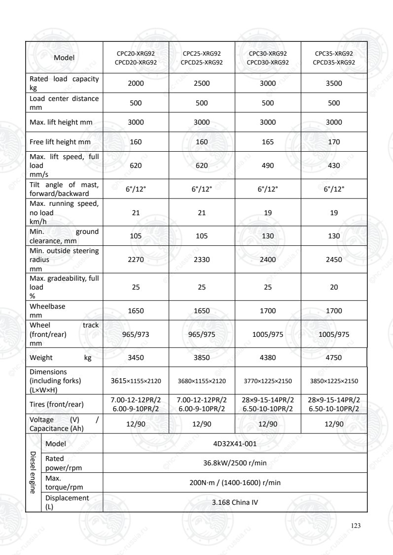
Страница 128
124
Model CPC38-XRG92 CPCD38-XRG92
Rated load capacity
kg 3800 3800
Load center distance
mm 500 500
Max. lift height mm 3000 3000
Free lift height mm 170 170
Max. lift speed, full
load
mm/s
430 430
Tilt angle of mast,
forward/backward
(°)
6°/12° 6°/12°
Max. running speed,
no load
km/h
19 19
Min. ground
clearance, mm 130 130
Min. outside steering
radius
mm
2480 2480
Max. gradeability,
full load
%
20 20
Wheelbase
mm 1700 1700
Wheel track
(front/rear)
mm
1005/970 1005/970
Weight kg 4950 4950
Dimensions
(including forks)
(L×W×H)
3880×1225×2150 3880×1225×2150
Tires (front/rear) 28×9-15-14PR/2
6.50-10-10PR/2
28×9-15-14PR/2
6.50-10-10PR/2
Voltage (V) /
Capacitance (Ah) 12/60 12/60
Dieselengine
Model 4D32X41-001
Rated
power/rpm 36.8kW/2500 r/min
Max.
torque/rpm 200N·m / (1400-1600) r/min
Displacement
(L) 3.168 China IV
Оригинальная страница: таблицы и схемы
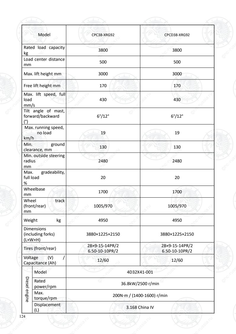
Страница 129
125
Model CPCD30-XRG92-GW CPCD35-XRG92-GW
Rated load capacity
kg 3000 3500
Load center distance
mm 500 500
Max. lift height mm 3000 3000
Free lift height mm 165 170
Max. lift speed, full
load
mm/s
490 430
Tilt angle of mast,
forward/backward
(°)
6°/12° 6°/12°
Max. running speed,
no load
km/h
19 19
Min. ground
clearance, mm 130 130
Min. outside steering
radius
mm
2400 2450
Max. gradeability,
full load
%
25 20
Wheelbase
mm 1700 1700
Wheel track
(front/rear)
mm
1005/970 1005/970
Weight kg 4380 4750
Dimensions
(including forks)
(L×W×H)
3770×1225×2450 3850×1225×2450
Tires (front/rear) 28×9-15-14PR/2
6.50-10-10PR/2
28×9-15-14PR/2
6.50-10-10PR/2
Voltage (V) /
Capacitance (Ah) 12/90 12/90
Dieselengine
Model 4D32X41-001
Rated
power/rpm 36.8kW/2500 r/min
Max.
torque/rpm 200N·m / (1400-1600) r/min
Displacement
(L) 3.168 China IV
Оригинальная страница: таблицы и схемы
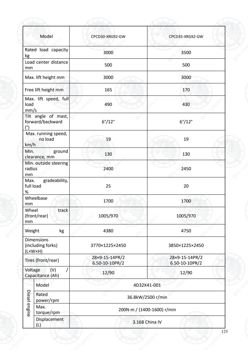
Страница 130
126
Model CPCD38-XRG92-GW
Rated load capacity
kg 3800
Load center distance
mm 500
Max. lift height mm 3000
Free lift height mm 170
Max. lift speed, full
load
mm/s
430
Tilt angle of mast,
forward/backward
(°)
6°/12°
Max. running speed,
no load
km/h
19
Min. ground
clearance, mm 130
Min. outside steering
radius
mm
2480
Max. gradeability,
full load
%
20
Wheelbase
mm 1700
Wheel track
(front/rear)
mm
1005/970
Weight kg 4950
Dimensions
(including forks)
(L×W×H)
3880×1225×2450
Tires (front/rear) 28×9-15-14PR/2
6.50-10-10PR/2
Voltage (V) /
Capacitance (Ah) 12/90
Gasolineengines
Model 4D32X41-001
Rated
power/rpm 36.8kW/2500 r/min
Max.
torque/rpm 200N·m / (1400-1600) r/min
Displacement
(L) 3.168 China IV
Оригинальная страница: таблицы и схемы
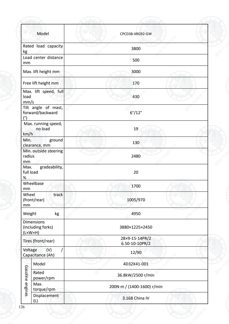
Страница 131
127
Model CPCD20-XRG92F CPCD25-XRG92F CPCD30-XRG92F CPCD35-XRG92F
Rated load capacity
kg 2000 2500 3000 3500
Load center distance
mm 500 500 500 500
Max. lift height mm 3000 3000 3000 3000
Free lift height mm 160 160 165 170
Max. lift speed, full
load
mm/s
620 620 490 430
Tilt angle of mast,
forward/backward 6°/12° 6°/12° 6°/12° 6°/12°
Max. running speed,
no load
km/h
21 21 19 19
Min. ground
clearance, mm 105 105 130 130
Min. outside steering
radius
mm
2270 2330 2400 2450
Max. gradeability, full
load
%
25 25 25 20
Wheelbase
mm 1650 1650 1700 1700
Wheel track
(front/rear)
mm
965/973 965/975 1005/975 1005/975
Weight kg 3450 3850 4380 4750
Dimensions
(including forks)
(L×W×H)
3615×1155×2120 3680×1155×2120 3770×1225×2150 3850×1225×2150
Tires (front/rear) 7.00-12-12PR/2
6.00-9-10PR/2
7.00-12-12PR/2
6.00-9-10PR/2
28×9-15-14PR/2
6.50-10-10PR/2
28×9-15-14PR/2
6.50-10-10PR/2
Voltage (V) /
Capacitance (Ah) 12/90 12/90 12/90 12/90
Dieselengine
Model 4D32X41-002
Rated
power/rpm 36.8kW/2500 r/min
Max.
torque/rpm 210N·m / (1400-1600) r/min
Displacement
(L) 3.168 China IV
Оригинальная страница: таблицы и схемы
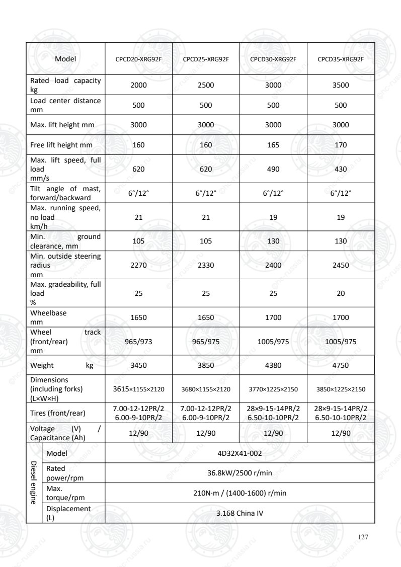
Страница 132
128
Model CPCD38-XRG92F
Rated load capacity
kg 3800
Load center distance
mm 500
Max. lift height mm 3000
Free lift height mm 170
Max. lift speed, full
load
mm/s
430
Tilt angle of mast,
forward/backward
(°)
6°/12°
Max. running speed,
no load
km/h
19
Min. ground
clearance, mm 130
Min. outside steering
radius
mm
2480
Max. gradeability,
full load
%
20
Wheelbase
mm 1700
Wheel track
(front/rear)
mm
1005/970
Weight kg 4950
Dimensions
(including forks)
(L×W×H)
3880×1225×2150
Tires (front/rear) 28×9-15-14PR/2
6.50-10-10PR/2
Voltage (V) /
Capacitance (Ah) 12/60
Gasolineengines
Model 4D32X41-002
Rated
power/rpm 36.8kW/2500 r/min
Max.
torque/rpm 210N·m / (1400-1600) r/min
Displacement
(L) 3.168 China IV
Оригинальная страница: таблицы и схемы
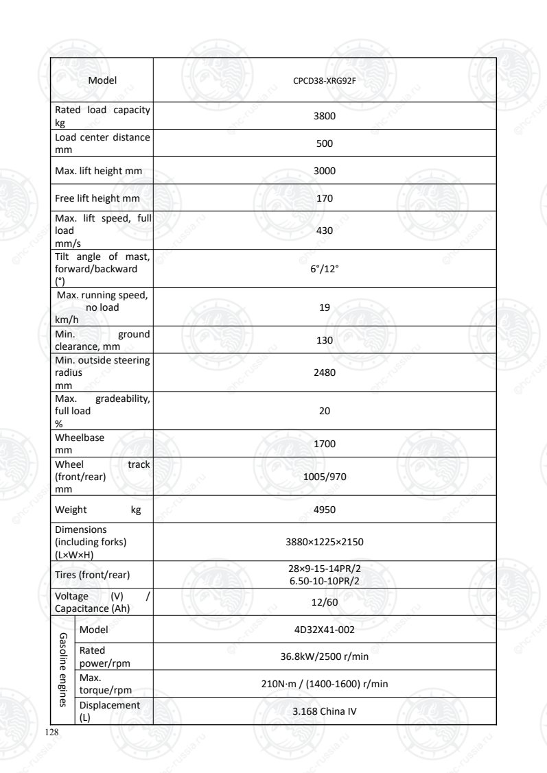
Страница 133
129
Model CPC20-XRW10
CPCD20-XRW10
CPC25-XRW10
CPCD25-XRW10
CPC30-XRW10
CPCD30-XRW10
Rated load capacity
kg 2000 2500 3000
Load center distance
mm 500 500 500
Max. lift height mm 3000 3000 3000
Free lift height mm 160 160 165
Max. lift speed, full
load
mm/s
590 590 470
Tilt angle of mast,
forward/backward 6°/12° 6°/12° 6°/12°
Max. running speed,
no load
km/h
21 21 19
Min. ground
clearance, mm 105 105 130
Min. outside steering
radius
mm
2270 2330 2400
Max. gradeability, full
load
%
20 15 15
Wheelbase
mm 1650 1650 1700
Wheel track
(front/rear)
mm
965/973 965/973 1005/975
Weight kg 3450 3850 4380
Dimensions
(including forks)
(L×W×H)
3610×1155×2120 3680×1155×2120 3770×1225×2150
Tires (front/rear) 7.00-12-12PR
6.00-9-10PR
7.00-12-12PR
6.00-9-10PR
28×9-15-14PR/2
6.50-10-10PR/2
Voltage (V) /
Capacitance (Ah) 12/90/20h 12/90/20h 12/90/20h
Dieselengine
Model ISUZU GK-C240NKFC-01
Rated
power/rpm 35.4kW/2500r/min
Max.
torque/rpm 139.9N·m/ 1800 r/min
Displacement
(L) 2.369
Оригинальная страница: таблицы и схемы
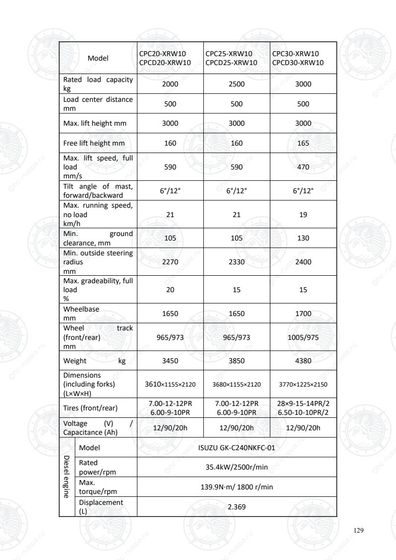
Страница 134
130
Model CPCD20-XRW33 CPCD25-XRW33 CPCD30-XRW33 CPCD35-XRW33
Rated load capacity
kg 2000 2500 3000 3500
Load center distance
mm 500 500 500 500
Max. lift height mm 3000 3000 3000 3000
Free lift height mm 160 160 165 170
Max. lift speed, full
load
mm/s
620 620 490 430
Tilt angle of mast,
forward/backward 6°/12° 6°/12° 6°/12° 6°/12°
Max. running speed,
no load
km/h
21 21 19 19
Min. ground
clearance, mm 105 105 130 130
Min. outside steering
radius
mm
2270 2330 2400 2450
Max. gradeability, full
load
%
25 25 25 20
Wheelbase
mm 1650 1650 1700 1700
Wheel track
(front/rear)
mm
965/973 965/973 1005/975 1005/975
Weight kg 3450 3850 4380 4750
Dimensions
(including forks)
(L×W×H)
3615×1155×2120 3680×1155×2120 3770×1225×2150 3850×1225×2150
Tires (front/rear) 7.00-12-12PR/2
6.00-9-10PR/2
7.00-12-12PR/2
6.00-9-10PR/2
28×9-15-14PR/2
6.50-10-10PR/2
28×9-15-14PR/2
6.50-10-10PR/2
Voltage (V) /
Capacitance (Ah) 12/90 12/90 12/90 12/90
Dieselengine
Model YANMAR 4TNE98
Rated
power/rpm 42.1kW/2300r/min
Max.
torque/rpm 186N·m/ 1700 r/min
Displacement
(L) 3.319
Оригинальная страница: таблицы и схемы
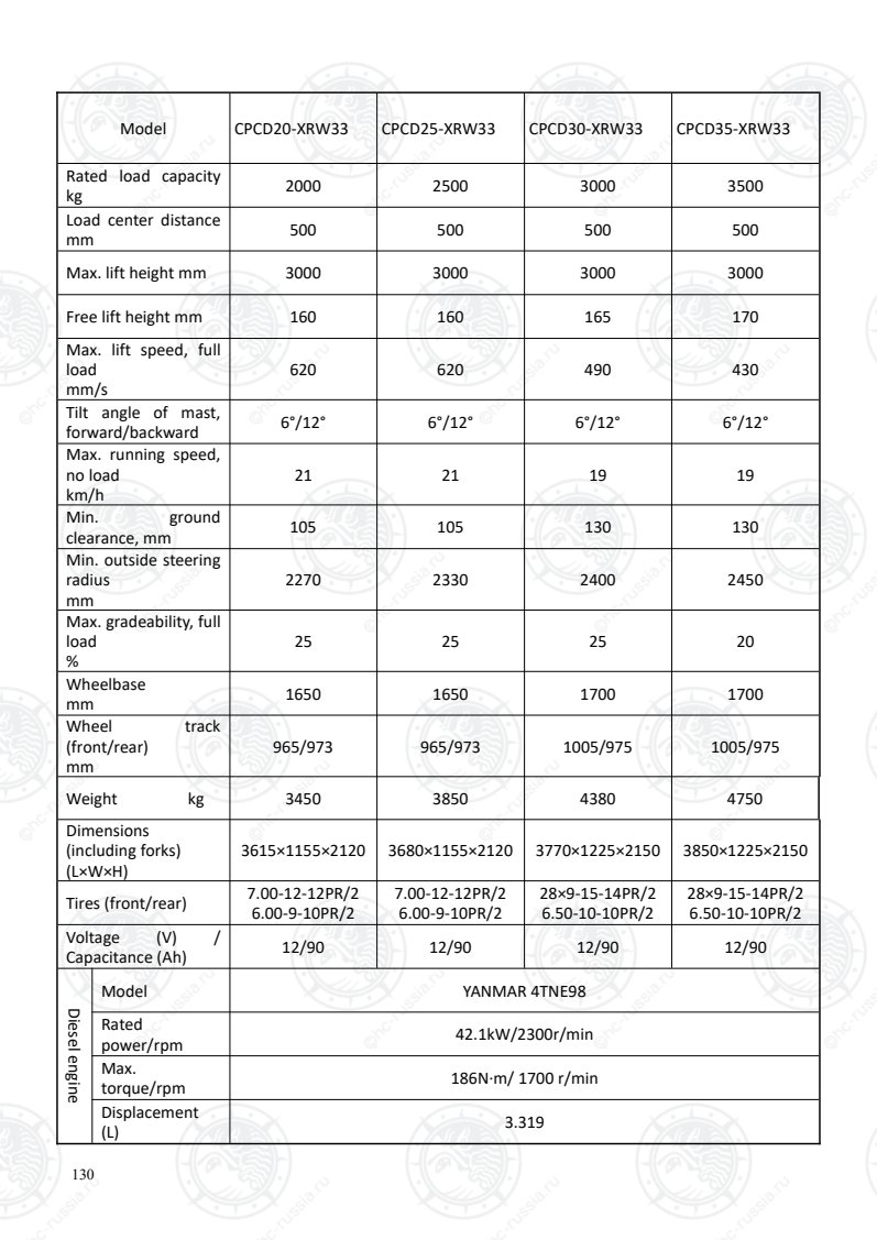
Страница 135
131
Model CPCD20-XRW43 CPCD25-XRW43 CPCD30-XRW43 CPCD35-XRW43
Rated load capacity
kg 2000 2500 3000 3500
Load center distance
mm 500 500 500 500
Max. lift height mm 3000 3000 3000 3000
Free lift height mm 160 160 165 170
Max. lift speed, full
load
mm/s
620 620 490 430
Tilt angle of mast,
forward/backward 6°/12° 6°/12° 6°/12° 6°/12°
Max. running speed,
no load
km/h
21 21 18 18
Min. ground
clearance, mm 105 105 130 130
Min. outside steering
radius
mm
2270 2330 2400 2440
Max. gradeability, full
load
%
20 20 20 20
Wheelbase
mm 1650 1650 1700 1700
Wheel track
(front/rear)
mm
965/973 965/973 1005/975 1005/975
Weight kg 3450 3850 4380 4750
Dimensions
(including forks)
(L×W×H)
3600×1155×2120 3675×1155×2120 3800×1225×2150 3870×1225×2170
Tires (front/rear) 7.00-12-12PR
6.00-9-10PR
7.00-12-12PR
6.00-9-10PR
28×9-15-14PR/2
6.50-10-10PR/2
28×9-15-14PR/2
6.50-10-10PR/2
Voltage (V) /
Capacitance (Ah) 12/90/20h 12/90/20h 12/90/20h 12/90/20h
Dieselengine
Model Cummins QSF2.8T3NA49
Rated
power/rpm 36.5kW/2500r/min
Max.
torque/rpm 186N·m/ 1500 r/min
Displacement
(L) 2.8
Оригинальная страница: таблицы и схемы
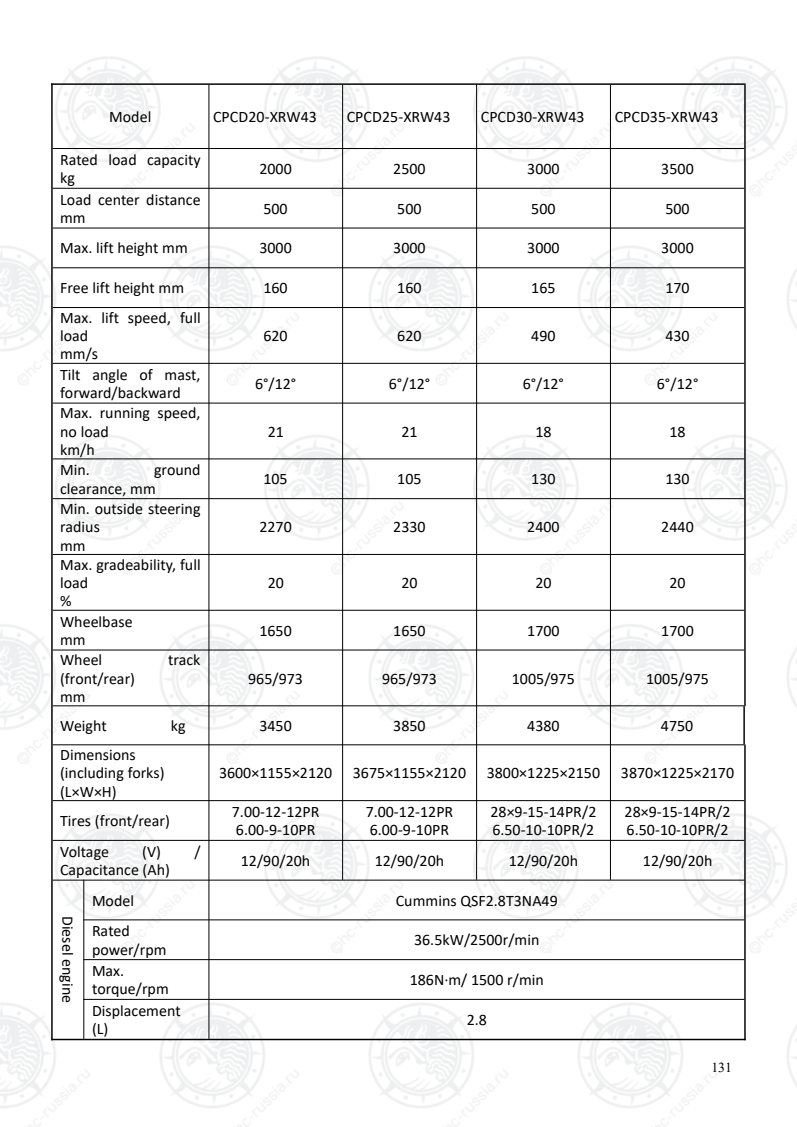
Страница 136
132
Model CPCD20-XRW56 CPCD25-XRW56 CPCD30-XRW56 CPCD35-XRW56
Rated load capacity
kg 2000 2500 3000 3500
Load center distance
mm 500 500 500 500
Max. lift height mm 3000 3000 3000 3000
Free lift height mm 160 160 165 170
Max. lift speed, full
load
mm/s
620 620 490 430
Tilt angle of mast,
forward/backward 6°/12° 6°/12° 6°/12° 6°/12°
Max. running speed,
no load
km/h
21 21 18 18
Min. ground
clearance, mm 105 105 130 130
Min. outside steering
radius
mm
2270 2330 2400 2440
Max. gradeability, full
load
%
20 20 20 20
Wheelbase
mm 1650 1650 1700 1700
Wheel track
(front/rear)
mm
965/973 965/973 1005/975 1005/975
Weight kg 3450 3850 4380 4750
Dimensions
(including forks)
(L×W×H)
3600×1155×2120 3675×1155×2120 3800×1225×2150 3870×1225×2170
Tires (front/rear) 7.00-12-12PR
6.00-9-10PR
7.00-12-12PR
6.00-9-10PR
28×9-15-14PR/2
6.50-10-10PR/2
28×9-15-14PR/2
6.50-10-10PR/2
Voltage (V) /
Capacitance (Ah) 12/90/20h 12/90/20h 12/90/20h 12/90/20h
Dieselengine
Model Yanmar 4TNV94L-BXPHZ
Rated
power/rpm 34.6kW/2400r/min
Max.
torque/rpm (191.5-208.5) N·m/ 1500(±100) r/min
Displacement
(L) 3.054
Оригинальная страница: таблицы и схемы
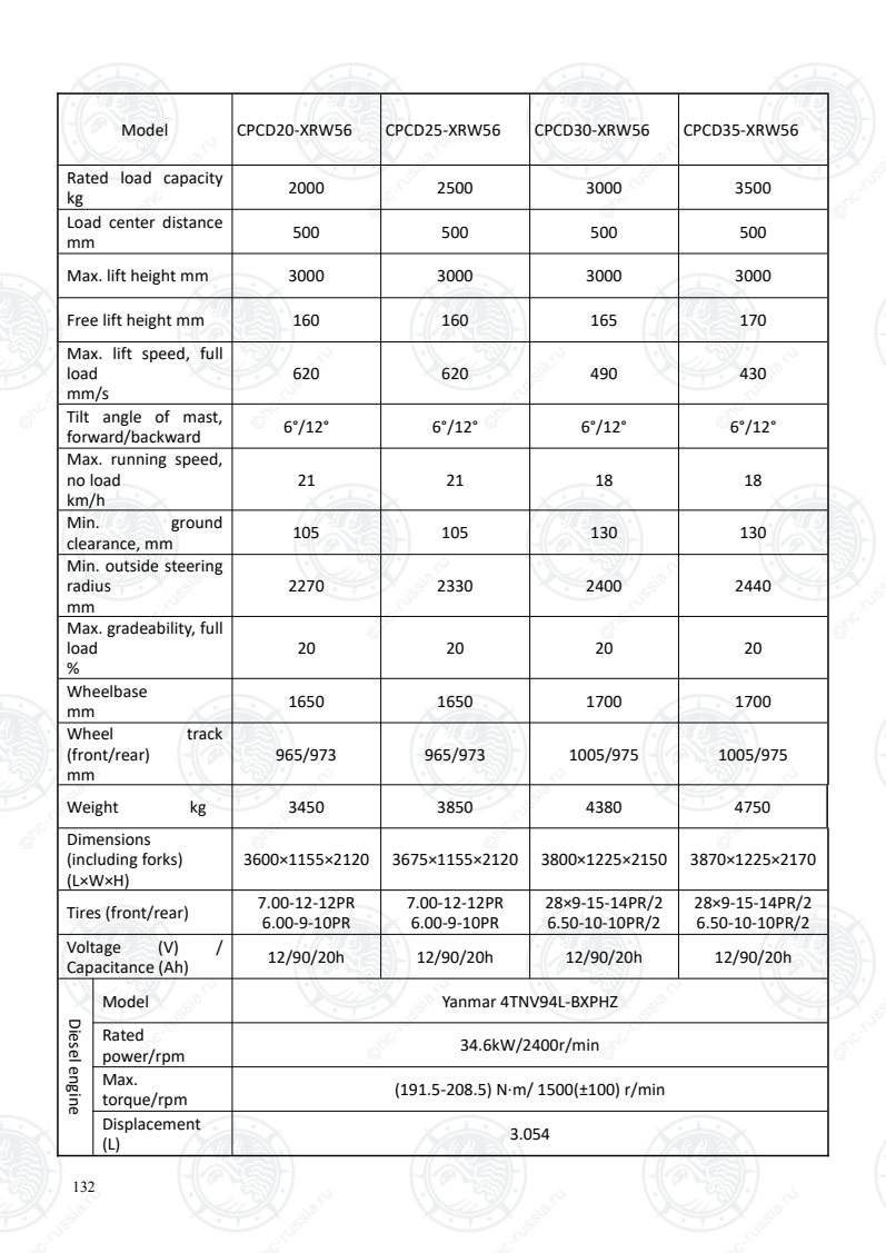
Страница 137
133
Model CPQD20-XRW22 CPQD25-XRW22 CPQD30-XRW22 CPQD35-XRW22
Rated load capacity
kg 2000 2500 3000 3500
Load center distance
mm 500 500 500 500
Max. lift height mm 3000 3000 3000 3000
Free lift height mm 160 160 165 170
Max. lift speed, full
load
mm/s
560 560 450 350
Tilt angle of mast,
forward/backward 6°/12° 6°/12° 6°/12° 6°/12°
Max. running speed,
no load
km/h
21 21 18 18
Min. ground
clearance, mm 105 105 130 130
Min. outside steering
radius
mm
2270 2330 2400 2440
Max. gradeability, full
load
%
20 20 20 20
Wheelbase
mm 1650 1650 1700 1700
Wheel track
(front/rear)
mm
965/973 965/973 1005/975 1005/975
Weight kg 3450 3850 4380 4750
Dimensions
(including forks)
(L×W×H)
3600×1155×2120 3675×1155×2120 3800×1225×2150 3870×1225×2170
Tires (front/rear) 7.00-12-12PR
6.00-9-10PR
7.00-12-12PR
6.00-9-10PR
28×9-15-14PR/2
6.50-10-10PR/2
28×9-15-14PR/2
6.50-10-10PR/2
Voltage (V) /
Capacitance (Ah) 12/60/20h 12/60/20h 12/60/20h 12/60/20h
Gasolineengines
Model GCT(NISSAN) K25
Rated
power/rpm 37.4kW/2300 r/min
Max.
torque/rpm 185N·m/1600 r/min
Displacement
(L) 2.488
Power type Gasoline
Оригинальная страница: таблицы и схемы
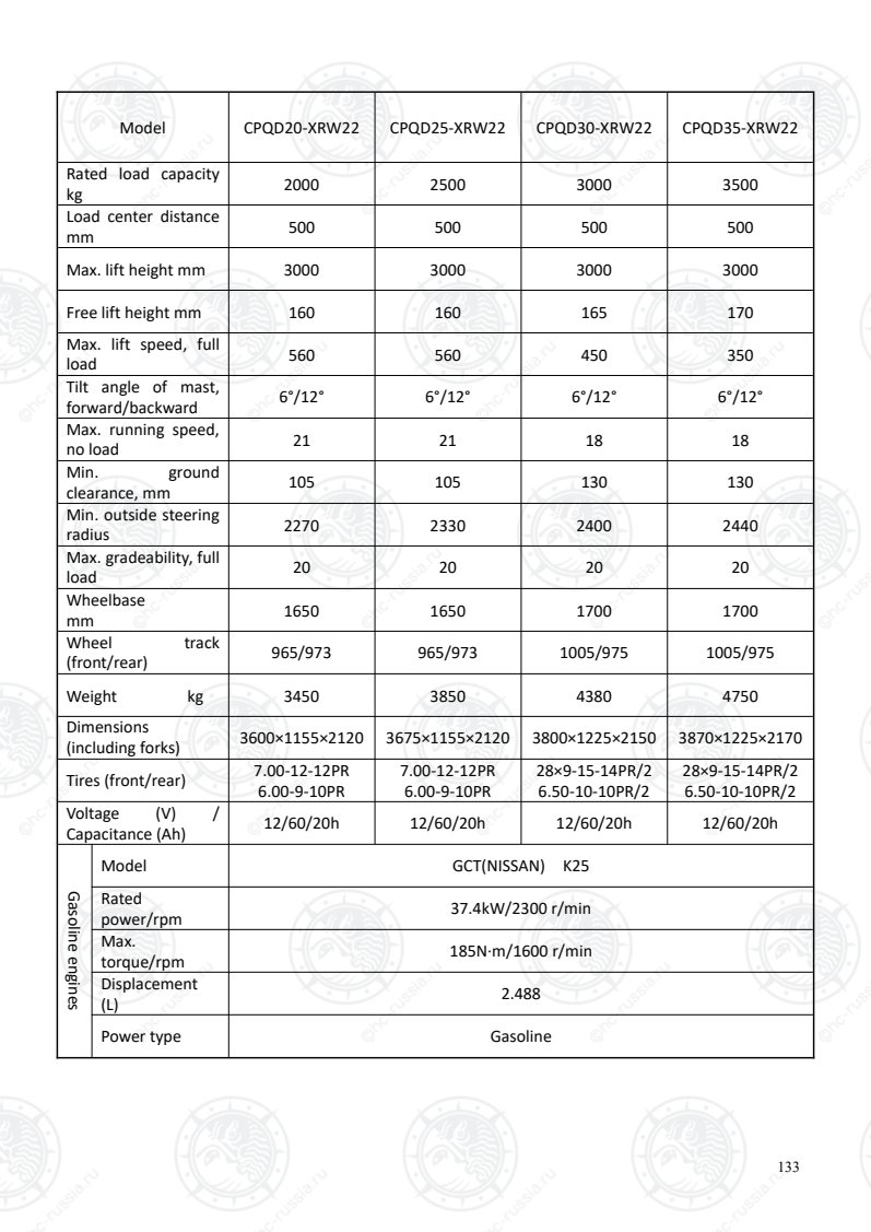
Страница 138
134
Model CPQYD20-XRW22 CPQYD25-XRW22 CPQYD30-XRW22 CPQYD35-XRW22
Rated load capacity
kg 2000 2500 3000 3500
Load center distance
mm 500 500 500 500
Max. lift height mm 3000 3000 3000 3000
Free lift height mm 160 160 165 170
Max. lift speed, full
load
mm/s
560 560 450 350
Tilt angle of mast,
forward/backward 6°/12° 6°/12° 6°/12° 6°/12°
Max. running speed,
no load
km/h
21 21 18 18
Min. ground
clearance, mm 105 105 130 130
Min. outside steering
radius
mm
2270 2330 2400 2440
Max. gradeability, full
load
%
20 20 20 20
Wheelbase
mm 1650 1650 1700 1700
Wheel track
(front/rear)
mm
965/973 965/973 1005/975 1005/975
Weight kg 3450 3850 4380 4750
Dimensions
(including forks)
(L×W×H)
3600×1155×2120 3675×1155×2120 3800×1225×2150 3870×1225×2170
Tires (front/rear) 7.00-12-12PR
6.00-9-10PR
7.00-12-12PR
6.00-9-10PR
28×9-15-14PR/2
6.50-10-10PR/2
28×9-15-14PR/2
6.50-10-10PR/2
Voltage (V) /
Capacitance (Ah) 12/60/20h 12/60/20h 12/60/20h 12/60/20h
Gasolineengines
Model GCT(NISSAN) K25
Rated
power/rpm 37.4kW/2300 r/min
Max.
torque/rpm 185N·m/1600 r/min
Displacement
(L) 2.488
Power type Gasoline/LPG
Оригинальная страница: таблицы и схемы
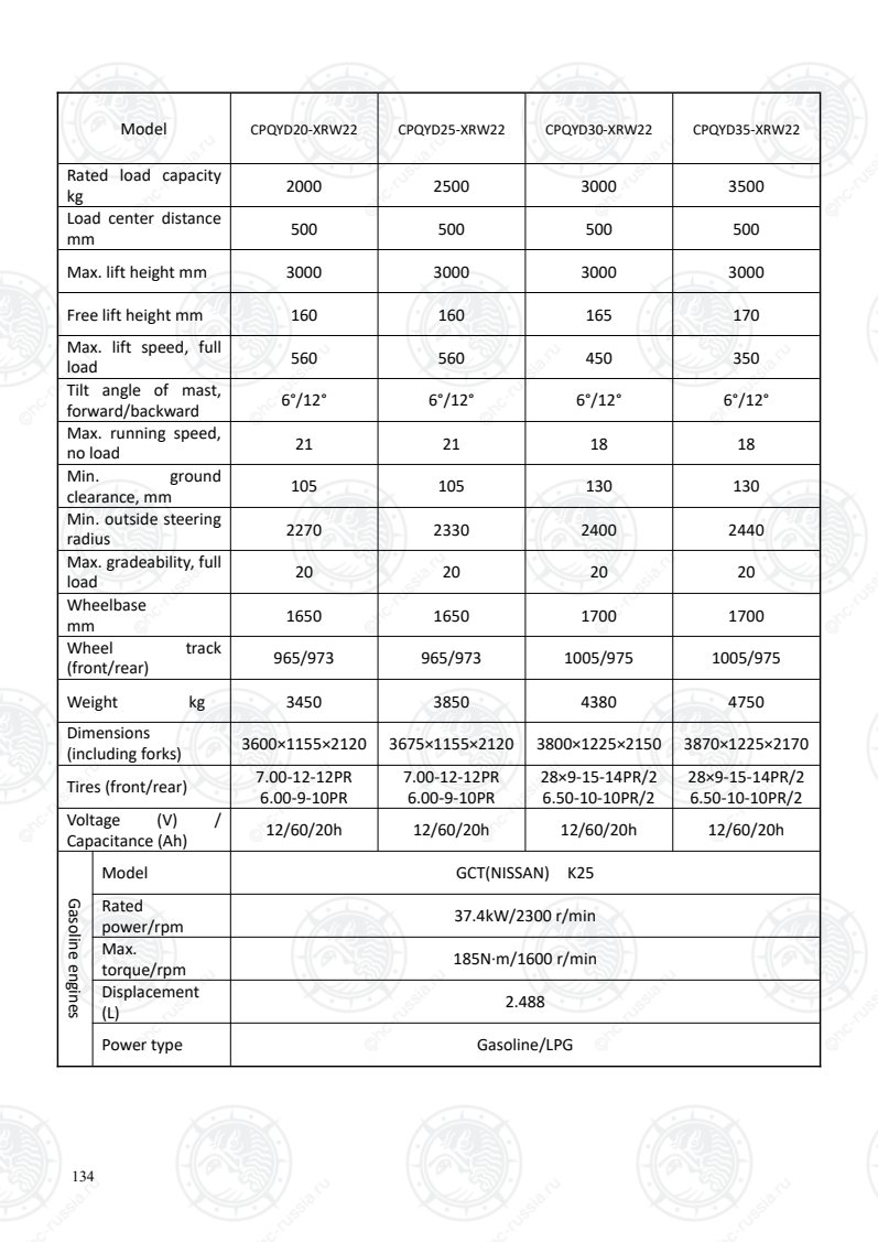
Страница 139
135
Model CPC20-XRW55
CPCD20-XRW55
CPC25-XRW55
CPCD25-XRW55
CPC30-XRW55
CPCD30-XRW55
CPC35-XRW55
CPCD35-XRW55
Rated load capacity
kg 2000 2500 3000 3500
Load center distance
mm 500 500 500 500
Max. lift height mm 3000 3000 3000 3000
Free lift height mm 160 160 165 170
Max. lift speed, full
load
mm/s
600 560 480 410
Tilt angle of mast,
forward/backward 6°/12° 6°/12° 6°/12° 6°/12°
Max. running speed,
no load
km/h
21 21 18 19
Min. ground
clearance, mm 105 105 130 130
Min. outside steering
radius
mm
2270 2330 2400 2450
Max. gradeability, full
load
%
25 20 20 20
Wheelbase
mm 1650 1650 1700 1700
Wheel track
(front/rear)
mm
965/973 965/973 1005/975 1005/975
Weight kg 3450 3850 4380 4750
Dimensions
(including forks)
(L×W×H)
3600×1155×2120 3675×1155×2120 3770×1225×2150 3850×1225×2150
Tires (front/rear) 7.00-12-12PR
6.00-9-10PR
7.00-12-12PR
6.00-9-10PR
28×9-15-14PR/2
6.50-10-10PR/2
28×9-15-14PR/2
6.50-10-10PR/2
Voltage (V) /
Capacitance (Ah) 12/60/20h 12/60/20h 12/90/20h 12/90/20h
Dieselengine
Model Mitsubishi S4S-DPEU2
Rated
power/rpm 35.3kW/2250r/min
Max.
torque/rpm 177N·m/ 1700 r/min
Displacement
(L) 3.331
Оригинальная страница: таблицы и схемы
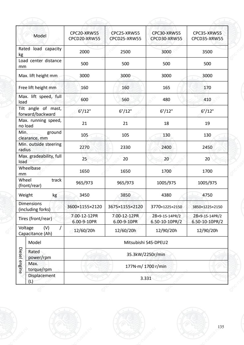
Страница 140
136
Model CPCD20-XRW92F CPCD25-XRW92F
Rated load capacity
kg 2000 2500
Load center distance
mm 500 500
Max. lift height mm 3000 3000
Free lift height mm 160 160
Max. lift speed, full
load
mm/s
620 620
Tilt angle of mast,
forward/backward
(°)
6°/12° 6°/12°
Max. running speed,
no load
km/h
21 21
Min. ground
clearance, mm 105 105
Min. outside steering
radius
mm
2270 2330
Max. gradeability,
full load
%
25 25
Wheelbase
mm 1650 1650
Wheel track
(front/rear)
mm
965/973 965/973
Weight kg 3450 3450
Dimensions
(including forks)
(L×W×H)
3615×1155×2120 3615×1155×2120
Tires (front/rear) 7.00-12-12PR/2
6.00-9-10PR/2
7.00-12-12PR/2
6.00-9-10PR/2
Voltage (V) /
Capacitance (Ah) 12/90 12/90
Dieselengine
Model 4D32XG30-300
Rated
power/rpm 36.8kW/2500 r/min
Max.
torque/rpm 186N·m/(1600-1800) r/min
Displacement
(L) 3.168
Оригинальная страница: таблицы и схемы
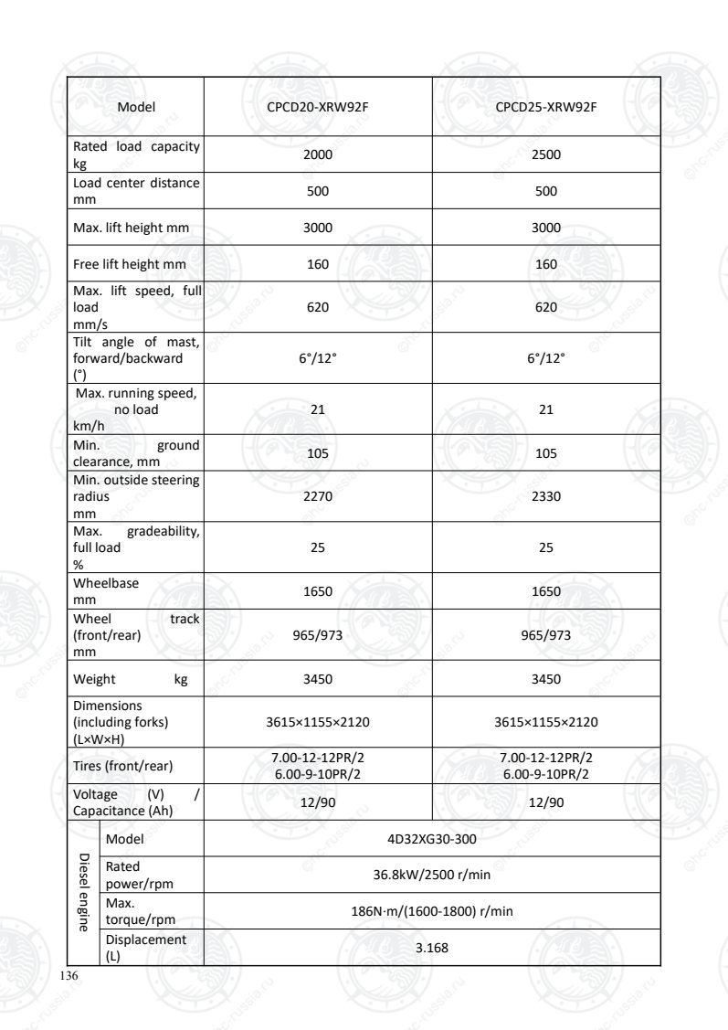
Страница 141
137
Model CPCD30-XRW92F CPCD35-XRW92F CPCD38-XRW92F
Rated load capacity
kg 3000 3500 3800
Load center distance
mm 500 500 500
Max. lift height mm 3000 3000 3000
Free lift height mm 165 170 170
Max. lift speed, full
load
mm/s
490 430 430
Tilt angle of mast,
forward/backward 6°/12° 6°/12° 6°/12°
Max. running speed,
no load
km/h
19 19 19
Min. ground
clearance, mm 130 130 130
Min. outside steering
radius
mm
2400 2450 2480
Max. gradeability, full
load
%
25 20 20
Wheelbase
mm 1650 1650 1700
Wheel track
(front/rear)
mm
965/973 965/973 1005/975
Weight kg 4380 4750 4950
Dimensions
(including forks)
(L×W×H)
3770×1225×2150 3850×1225×2150 3880×1225×2150
Tires (front/rear) 28×9--10-14PR/2
6.50-10-10PR/2
28×9--15-14PR/2
6.50-10-10PR/2
28×9-15-14PR/2
6.50-10-10PR/2
Voltage (V) /
Capacitance (Ah) 12/90 12/90 12/90
Dieselengine
Model 4D32XG30-300
Rated
power/rpm 36.8kW/2500r/min
Max.
torque/rpm 186N·m/(1,600-1,800) r/min
Displacement
(L) 3.168
Оригинальная страница: таблицы и схемы
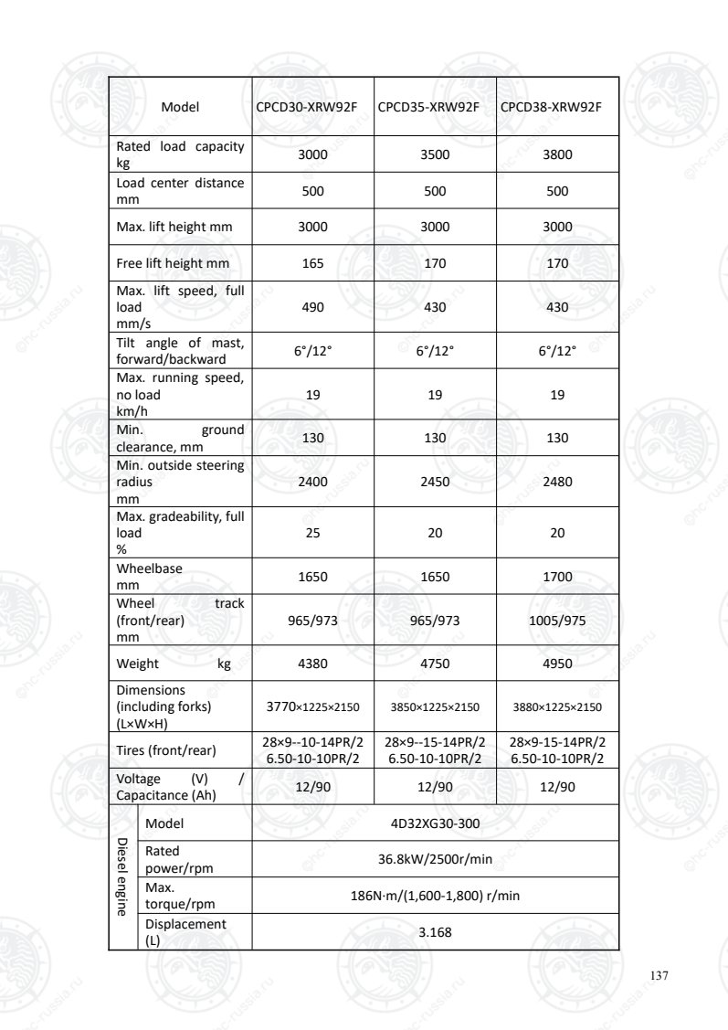
Страница 142
138
Model CPCD20-XRG59 CPCD25-XRG59 CPCD30-XRG59 CPCD35-XRG59
Rated load capacity
kg 2000 2500 3000 3500
Load center distance
mm 500 500 500 500
Max. lift height mm 3000 3000 3000 3000
Free lift height mm 160 160 165 170
Max. lift speed, full
load
mm/s
630 630 510 440
Tilt angle of mast,
forward/backward 6°/12° 6°/12° 6°/12° 6°/12°
Max. running speed,
no load
km/h
20 20 19 19
Min. ground
clearance, mm 105 105 130 130
Min. outside steering
radius
mm
2270 2330 2400 2450
Max. gradeability, full
load
%
25 25 25 20
Wheelbase
mm 1650 1650 1700 1700
Wheel track
(front/rear)
mm
965/973 965/973 1005/975 1005/975
Weight kg 3450 3850 4380 4750
Dimensions
(including forks)
(L×W×H)
3615×1155×2120 3680×1155×2120 3770×1225×2150 3850×1225×2150
Tires (front/rear) 28×9-15-14PR/2
6.50-10-10PR/2
28×9-15-14PR/2
6.50-10-10PR/2
28×9-15-14PR/2
6.50-10-10PR/2
28×9-15-14PR/2
6.50-10-10PR/2
Voltage (V) /
Capacitance (Ah) 12/90 12/90 12/90 12/90
Dieselengine
Model CA498-05T3-A250
Rated
power/rpm 36kW/2500r/min
Max.
torque/rpm 196N·m/ 1800 r/min
Displacement
(L) 3.168
Оригинальная страница: таблицы и схемы
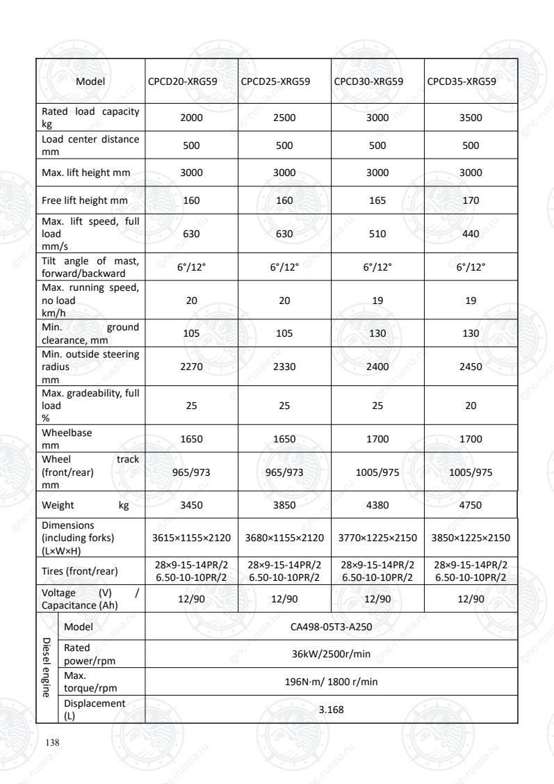
Страница 143
139
Model CPCD20-XRG60 CPCD25-XRG60 CPCD30-XRG60 CPCD35-XRG60
Rated load capacity
kg 2000 2500 3000 3500
Load center distance
mm 500 500 500 500
Max. lift height mm 3000 3000 3000 3000
Free lift height mm 160 160 165 170
Max. lift speed, full
load
mm/s
630 630 510 440
Tilt angle of mast,
forward/backward 6°/12° 6°/12° 6°/12° 6°/12°
Max. running speed,
no load
km/h
20 20 19 19
Min. ground
clearance, mm 105 105 130 130
Min. outside steering
radius
mm
2270 2330 2400 2450
Max. gradeability, full
load
%
25 25 25 20
Wheelbase
mm 1650 1650 1700 1700
Wheel track
(front/rear)
mm
965/973 965/973 1005/975 1005/975
Weight kg 3450 3850 4380 4750
Dimensions
(including forks)
(L×W×H)
3615×1155×2120 3680×1155×2120 3770×1225×2150 3850×1225×2150
Tires (front/rear) 28×9-15-14PR/2
6.50-10-10PR/2
28×9-15-14PR/2
6.50-10-10PR/2
28×9-15-14PR/2
6.50-10-10PR/2
28×9-15-14PR/2
6.50-10-10PR/2
Voltage (V) /
Capacitance (Ah) 12/90 12/90 12/90 12/90
Dieselengine
Model CA498-05T3-A250
Rated
power/rpm 36kW/2500r/min
Max.
torque/rpm 196N·m/ 1800 r/min
Displacement
(L) 3.168
Оригинальная страница: таблицы и схемы
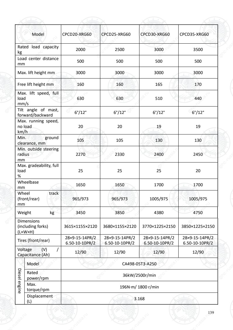
Страница 144
140
Model CPYD20-XRW52B CPYD25-XRW52B CPYD30-XRW52B CPYD35-XRW52B
Rated load capacity
kg 2000 2500 3000 3500
Load center distance
mm 500 500 500 500
Max. lift height mm 3000 3000 3000 3000
Free lift height mm 160 160 165 170
Max. lift speed, full
load
mm/s
560 560 450 385
Tilt angle of mast,
forward/backward 6°/12° 6°/12° 6°/12° 6°/12°
Max. running speed,
no load
km/h
21 21 20 20
Min. ground
clearance, mm 105 105 130 130
Min. outside steering
radius
mm
2270 2330 2400 2450
Max. gradeability, full
load
%
20 20 20 15
Wheelbase
mm 1650 1650 1700 1700
Wheel track
(front/rear)
mm
965/973 965/973 1005/975 1005/975
Weight kg 3450 3850 4380 4750
Dimensions
(including forks)
(L×W×H)
3615×1155×2120 3680×1155×2120 3770×1225×2150 3850×1225×2150
Tires (front/rear) 7.00-12-12PR
6.00-9-10PR
7.00-12-12PR
6.00-9-10PR
28×9-15-14PR/2
6.50-10-10PR/2
28×9-15-14PR/2
6.50-10-10PR/2
Voltage (V) /
Capacitance (Ah) 12/60 12/60 12/60 12/60
Gasolineengines
Model GCT GK25 LPG
Rated
power/rpm 35kW/2400 r/min
Max.
torque/rpm 170N·m/1600 r/min
Displacement
(L) 2.488
Power type LPG
Оригинальная страница: таблицы и схемы
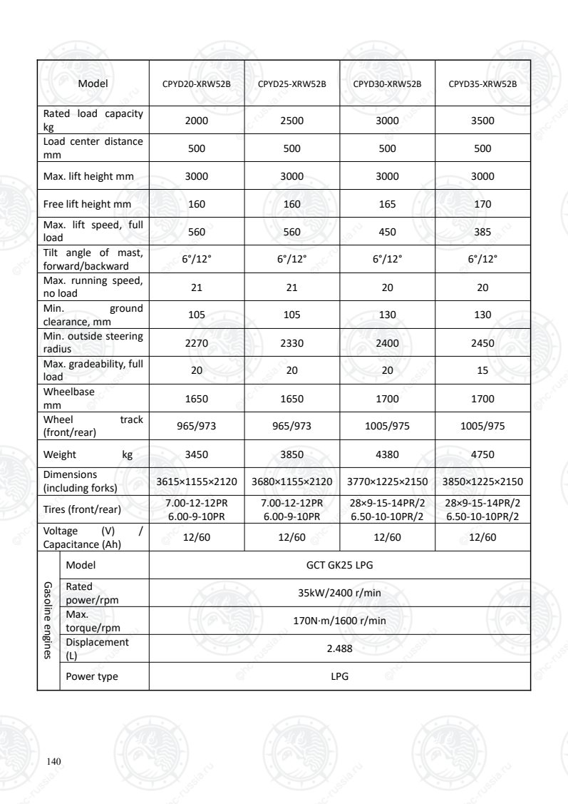
Страница 145
141
Model CPYD38-XRW52B
Rated load capacity
kg 3800
Load center distance
mm 500
Max. lift height mm 3000
Free lift height mm 170
Max. lift speed, full
load
mm/s
385
Tilt angle of mast,
forward/backward
(°)
6°/12°
Max. running speed,
no load
km/h
20
Min. ground
clearance, mm 130
Min. outside steering
radius
mm
2480
Max. gradeability,
full load
%
15
Wheelbase
mm 1700
Wheel track
(front/rear)
mm
1005/975
Weight kg 4950
Dimensions
(including forks)
(L×W×H)
3880×1225×2150
Tires (front/rear) 28×9-15-14PR/2
6.50-10-10PR/2
Voltage (V) /
Capacitance (Ah) 12/60
Gasolineengines
Model GCT GK25 LPG
Rated
power/rpm 35kW/2400 r/min
Max.
torque/rpm 170N·m/1600 r/min
Displacement
(L) 2.488
Power type LPG
Оригинальная страница: таблицы и схемы
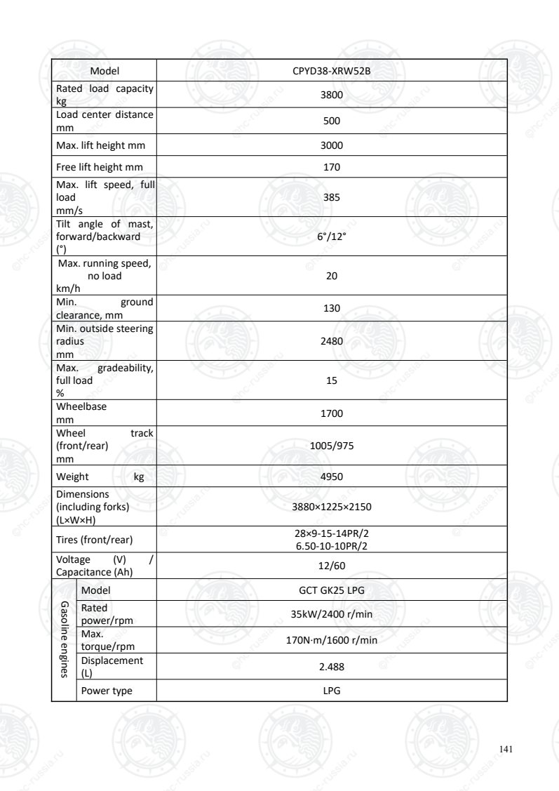
Страница 146
142
Model CPYD20-XRW52F CPYD25-XRW52F CPYD30-XRW52F CPYD35-XRW52F
Rated load capacity
kg 2000 2500 3000 3500
Load center distance
mm 500 500 500 500
Max. lift height mm 3000 3000 3000 3000
Free lift height mm 160 160 165 170
Max. lift speed, full
load
mm/s
560 560 450 385
Tilt angle of mast,
forward/backward 6°/12° 6°/12° 6°/12° 6°/12°
Max. running speed,
no load
km/h
19 19 17.9 17.9
Min. ground
clearance, mm 105 105 130 130
Min. outside steering
radius
mm
2270 2330 2400 2450
Max. gradeability, full
load
%
20 20 20 20
Wheelbase
mm 1650 1650 1700 1700
Wheel track
(front/rear)
mm
965/973 965/973 1005/975 1005/975
Weight kg 3450 3850 4380 4750
Dimensions
(including forks)
(L×W×H)
3615×1155×2120 3680×1155×2120 3770×1225×2150 3850×1225×2150
Tires (front/rear) 7.00-12-12PR
6.00-9-10PR
7.00-12-12PR
6.00-9-10PR
28×9-15-14PR/2
6.50-10-10PR/2
28×9-15-14PR/2
6.50-10-10PR/2
Voltage (V) /
Capacitance (Ah) 12/60 12/60 12/60 12/60
Gasolineengines
Model GCT GK25 LPG
Rated
power/rpm 35kW/2400 r/min
Max.
torque/rpm 170N·m/1600 r/min
Displacement
(L) 2.488
Power type LPG
Оригинальная страница: таблицы и схемы
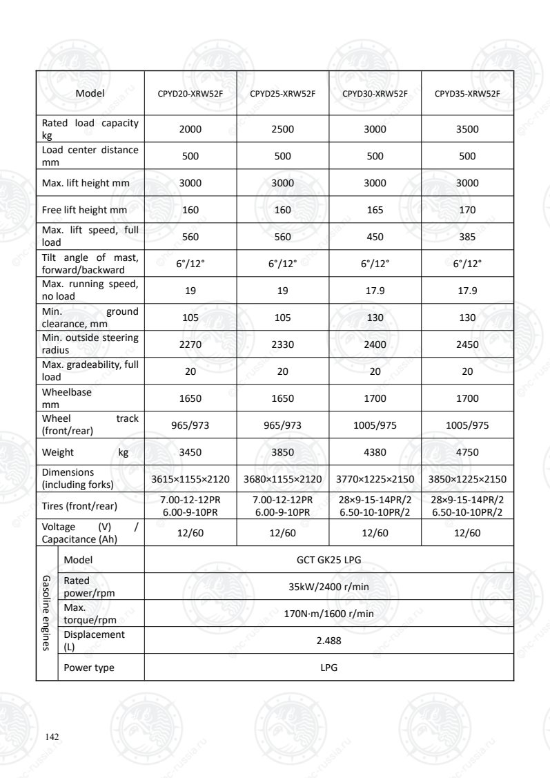
Страница 147
143
Model CPYD38-XRW52F
Rated load capacity
kg 3800
Load center distance
mm 500
Max. lift height mm 3000
Free lift height mm 170
Max. lift speed, full
load
mm/s
385
Tilt angle of mast,
forward/backward
(°)
6°/12°
Max. running speed,
no load
km/h
17.9
Min. ground
clearance, mm 130
Min. outside steering
radius
mm
2480
Max. gradeability,
full load
%
20
Wheelbase
mm 1700
Wheel track
(front/rear)
mm
1005/975
Weight kg 4950
Dimensions
(including forks)
(L×W×H)
3880×1225×2150
Tires (front/rear) 28×9-15-14PR/2
6.50-10-10PR/2
Voltage (V) /
Capacitance (Ah) 12/60
Gasolineengines
Model GCT GK25 LPG
Rated
power/rpm 35kW/2400 r/min
Max.
torque/rpm 170N·m/1600 r/min
Displacement
(L) 2.488
Power type LPG
Оригинальная страница: таблицы и схемы
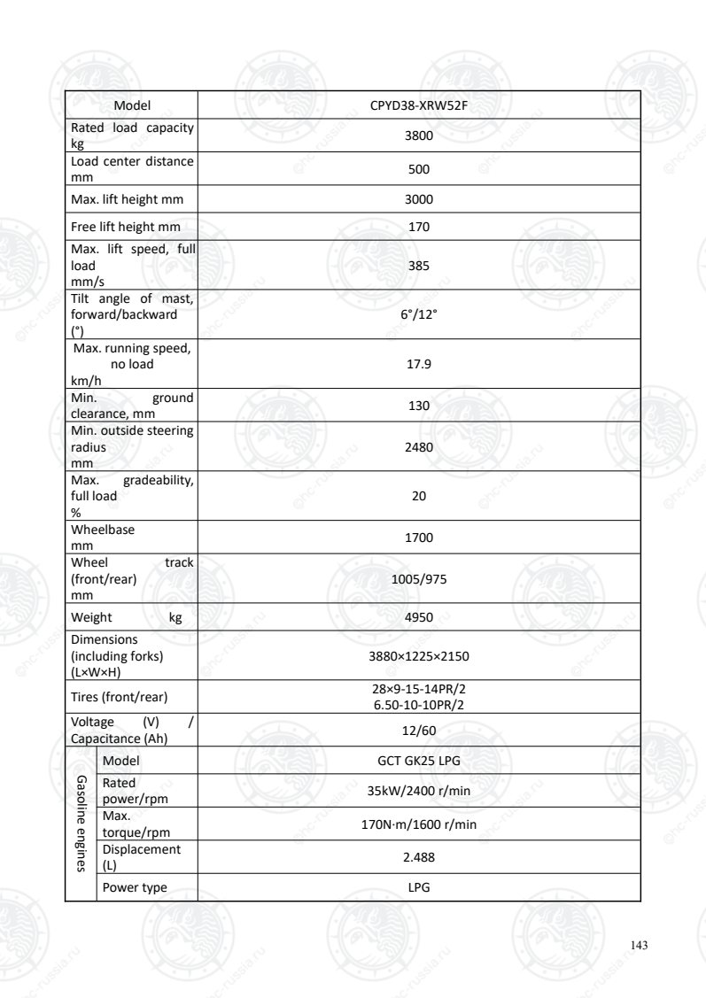
Страница 148
144
Model CPCD20-XRH5 CPCD25-XRH5 CPCD30-XRH5 CPCD35-XRH5
Rated load capacity
kg 2000 2500 3000 3500
Load center distance
mm 500 500 500 500
Max. lift height mm 3000 3000 3000 3000
Free lift height mm 160 160 165 170
Max. lift speed, full
load
mm/s
620 620 490 430
Tilt angle of mast,
forward/backward 6°/12° 6°/12° 6°/12° 6°/12°
Max. running speed,
no load
km/h
20 20 18 18
Min. ground
clearance, mm 105 105 130 130
Min. outside steering
radius
mm
2270 2330 2400 2450
Max. gradeability, full
load
%
20 20 20 18
Wheelbase
mm 1650 1650 1700 1700
Wheel track
(front/rear)
mm
965/973 965/975 1005/975 1005/975
Weight kg 3450 3850 4380 4700
Dimensions
(including forks)
(L×W×H)
3615×1155×2120 3680×1155×2120 3770×1225×2150 3850×1225×2150
Tires (front/rear) 7.00-12-12PR/2
6.00-9-10PR/2
7.00-12-12PR/2
6.00-9-10PR/2
28×9-15-14PR/2
6.50-10-10PR/2
28×9-15-14PR/2
6.50-10-10PR/2
Voltage (V) /
Capacitance (Ah) 12/90 12/90 12/90 12/90
Dieselengine
Model Cummins F2.8CS449
Rated
power/rpm 36kW/2500 r/min
Max.
torque/rpm 186N·m/ 1500 r/min
Displacement
(L) 2.8
Emission
standards China IV
Оригинальная страница: таблицы и схемы
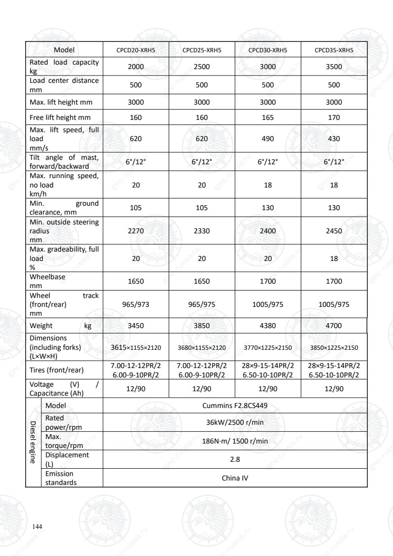
Страница 149
145
Model CPCD38-XRH5
Rated load capacity
kg 3800
Load center distance
mm 500
Max. lift height mm 3000
Free lift height mm 170
Max. lift speed, full
load
mm/s
430
Tilt angle of mast,
forward/backward
(°)
6°/12°
Max. running speed,
no load
km/h
18.6
Min. ground
clearance, mm 130
Min. outside steering
radius
mm
2480
Max. gradeability,
full load
%
15
Wheelbase
mm 1700
Wheel track
(front/rear)
mm
1005/975
Weight kg 4950
Dimensions
(including forks)
(L×W×H)
3880×1225×2150
Tires (front/rear) 28×9-15-14PR/2
6.50-10-10PR/2
Voltage (V) /
Capacitance (Ah) 12/90
Dieselengine
Model Cummins F2.8CS449
Rated
power/rpm 36kW/2500 r/min
Max.
torque/rpm 186N·m/ 1500 r/min
Displacement
(L) 2.8
Emission
standards China IV
Оригинальная страница: таблицы и схемы
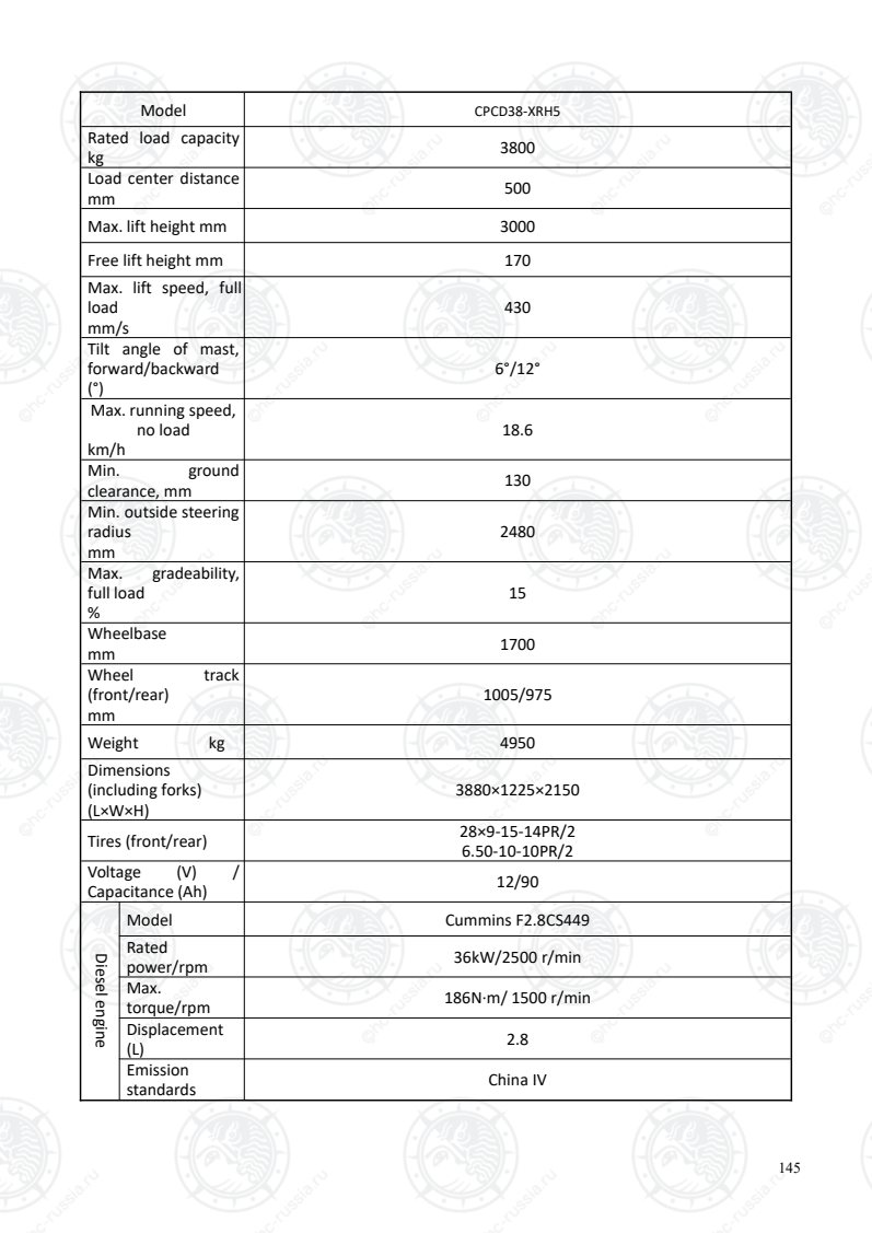
Страница 150
146
Model CPCD20-XRH5F CPCD25-XRH5F CPCD30-XRH5F CPCD35-XRH5F
Rated load capacity
kg 2000 2500 3000 3500
Load center distance
mm 500 500 500 500
Max. lift height mm 3000 3000 3000 3000
Free lift height mm 160 160 165 170
Max. lift speed, full
load
mm/s
620 620 490 430
Tilt angle of mast,
forward/backward 6°/12° 6°/12° 6°/12° 6°/12°
Max. running speed,
no load
km/h
17.5 17.5 18.6 18.6
Min. ground
clearance, mm 105 105 130 130
Min. outside steering
radius
mm
2270 2330 2400 2450
Max. gradeability, full
load
%
20 20 20 18
Wheelbase
mm 1650 1650 1700 1700
Wheel track
(front/rear)
mm
965/973 965/975 1005/975 1005/975
Weight kg 3450 3850 4380 4750
Dimensions
(including forks)
(L×W×H)
3615×1155×2120 3680×1155×2120 3770×1225×2150 3850×1225×2150
Tires (front/rear) 7.00-12-12PR/2
6.00-9-10PR/2
7.00-12-12PR/2
6.00-9-10PR/2
28×9-15-14PR/2
6.50-10-10PR/2
28×9-15-14PR/2
6.50-10-10PR/2
Voltage (V) /
Capacitance (Ah) 12/90 12/90 12/90 12/90
Dieselengine
Model Cummins F2.8CS449
Rated
power/rpm 36kW/2500 r/min
Max.
torque/rpm 186N·m/ 1500 r/min
Displacement
(L) 2.8
Emission
standards China IV
Оригинальная страница: таблицы и схемы
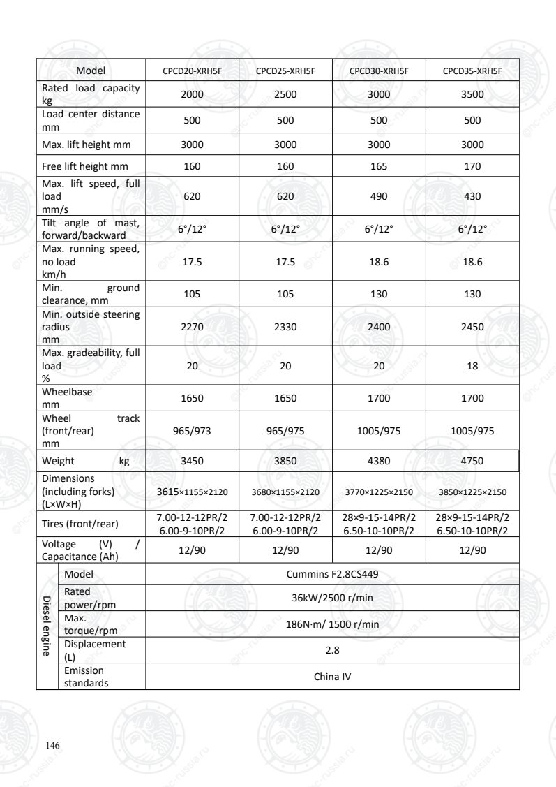
Страница 151
147
Model CPCD38-XRH5F
Rated load capacity
kg 3800
Load center distance
mm 500
Max. lift height mm 3000
Free lift height mm 170
Max. lift speed, full
load
mm/s
430
Tilt angle of mast,
forward/backward
(°)
6°/12°
Max. running speed,
no load
km/h
18.6
Min. ground
clearance, mm 130
Min. outside steering
radius
mm
2480
Max. gradeability,
full load
%
15
Wheelbase
mm 1700
Wheel track
(front/rear)
mm
1005/975
Weight kg 4950
Dimensions
(including forks)
(L×W×H)
3880×1225×2150
Tires (front/rear) 28×9-15-14PR/2
6.50-10-10PR/2
Voltage (V) /
Capacitance (Ah) 12/90
Dieselengine
Model Cummins F2.8CS449
Rated
power/rpm 36kW/2500 r/min
Max.
torque/rpm 186N·m/ 1500 r/min
Displacement
(L) 2.8
Emission
standards China IV
Оригинальная страница: таблицы и схемы
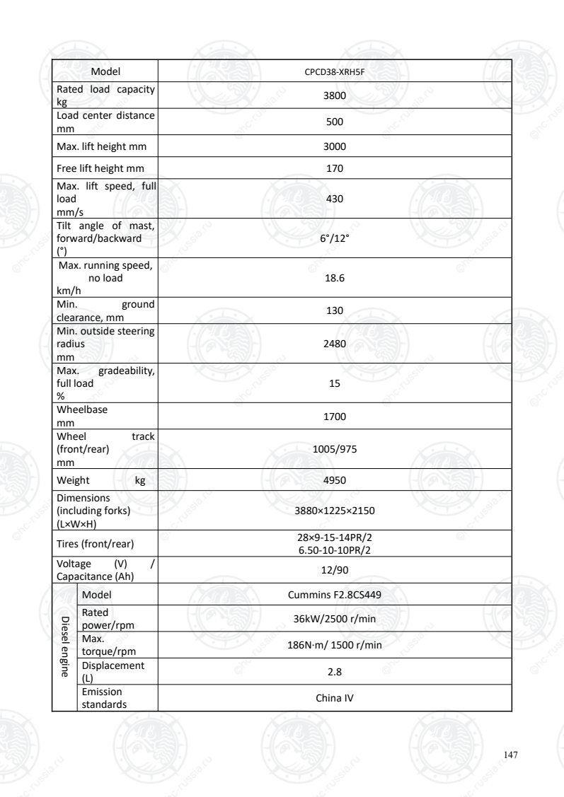
Страница 152
148
Model CPCD20-XRH5B1 CPCD25-XRH5B1 CPCD30-XRH5B1 CPCD35-XRH5B1
Rated load capacity
kg 2000 2500 3000 3500
Load center distance
mm 500 500 500 500
Max. lift height mm 3000 3000 3000 3000
Free lift height mm 160 160 165 170
Max. lift speed, full
load
mm/s
620 620 490 430
Tilt angle of mast,
forward/backward 6°/12° 6°/12° 6°/12° 6°/12°
Max. running speed,
no load
km/h
17.5 17.5 18.6 18.6
Min. ground
clearance, mm 105 105 130 130
Min. outside steering
radius
mm
2270 2330 2400 2450
Max. gradeability, full
load
%
20 20 20 18
Wheelbase
mm 1650 1650 1700 1700
Wheel track
(front/rear)
mm
965/973 965/975 1005/975 1005/975
Weight kg 3450 3850 4380 4750
Dimensions
(including forks)
(L×W×H)
3615×1155×2120 3680×1155×2120 3770×1225×2150 3850×1225×2150
Tires (front/rear) 7.00-12-12PR/2
6.00-9-10PR/2
7.00-12-12PR/2
6.00-9-10PR/2
28×9-15-14PR/2
6.50-10-10PR/2
28×9-15-14PR/2
6.50-10-10PR/2
Voltage (V) /
Capacitance (Ah) 12/90 12/90 12/90 12/90
Dieselengine
Model Cummins F2.8CS449
Rated
power/rpm 36kW/2500 r/min
Max.
torque/rpm 186N·m/ 1500 r/min
Displacement
(L) 2.8
Emission
standards China IV
Оригинальная страница: таблицы и схемы
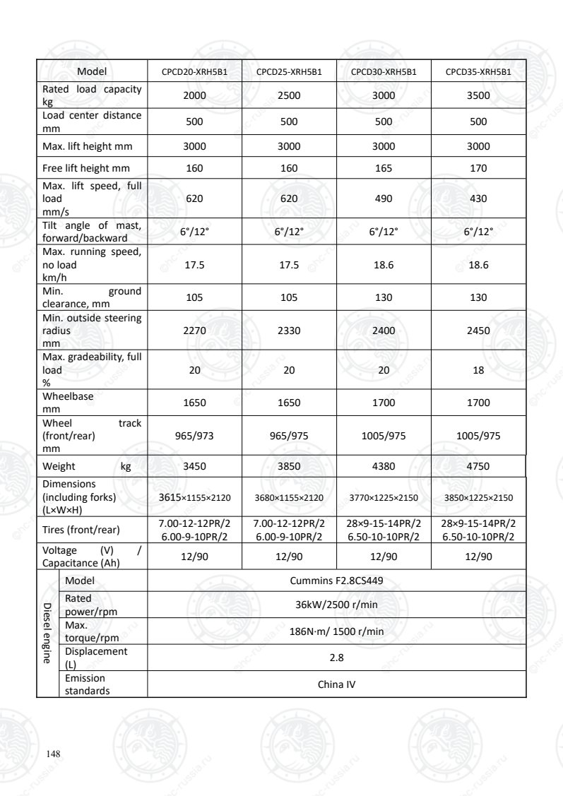
Страница 153
149
Model CPCD38-XRH5B1
Rated load capacity
kg 3800
Load center distance
mm 500
Max. lift height mm 3000
Free lift height mm 170
Max. lift speed, full
load
mm/s
430
Tilt angle of mast,
forward/backward
(°)
6°/12°
Max. running speed,
no load
km/h
18.6
Min. ground
clearance, mm 130
Min. outside steering
radius
mm
2480
Max. gradeability,
full load
%
15
Wheelbase
mm 1700
Wheel track
(front/rear)
mm
1005/975
Weight kg 4950
Dimensions
(including forks)
(L×W×H)
3880×1225×2150
Tires (front/rear) 28×9-15-14PR/2
6.50-10-10PR/2
Voltage (V) /
Capacitance (Ah) 12/90
Dieselengine
Model Cummins F2.8CS449
Rated
power/rpm 36kW/2500 r/min
Max.
torque/rpm 186N·m/ 1500 r/min
Displacement
(L) 2.8
Emission
standards China IV
Оригинальная страница: таблицы и схемы
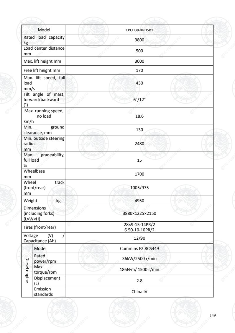
Страница 154
150
Model CPCD20-XRG2 CPCD25-XRG2 CPCD30-XRG2 CPCD35-XRG2
Rated load capacity
kg 2000 2500 3000 3500
Load center distance
mm 500 500 500 500
Max. lift height mm 3000 3000 3000 3000
Free lift height mm 160 160 165 170
Max. lift speed, full
load
mm/s
620 620 490 430
Tilt angle of mast,
forward/backward 6°/12° 6°/12° 6°/12° 6°/12°
Max. running speed,
no load
km/h
22 22 20 19
Min. ground
clearance, mm 105 130 130 130
Min. outside steering
radius
mm
2270 2330 2400 2450
Max. gradeability, full
load
%
20 20 20 20
Wheelbase
mm 1650 1650 1700 1700
Wheel track
(front/rear)
mm
965/973 965/973 1005/975 1005/975
Weight kg 3450 3850 4380 4750
Dimensions
(including forks)
(L×W×H)
3615×1155×2120 3680×1155×2120 3770×1225×2150 3850×1225×2150
Tires (front/rear) 7-12-12PR/2
6.00-9-10PR/2
7-12-12PR/2
6.00-9-10PR/2
28×9-15-14PR/2
6.50-10-10PR/2
28×9-15-14PR/2
6.50-10-10PR/2
Voltage (V) /
Capacitance (Ah) 12/90 12/90 12/90 12/90
Dieselengine
Model C490BPG-416
Rated
power/rpm 40kW/2650 r/min
Max.
torque/rpm 160N·m / (1800-2000) r/min
Displacement
(L) 2.67
Оригинальная страница: таблицы и схемы
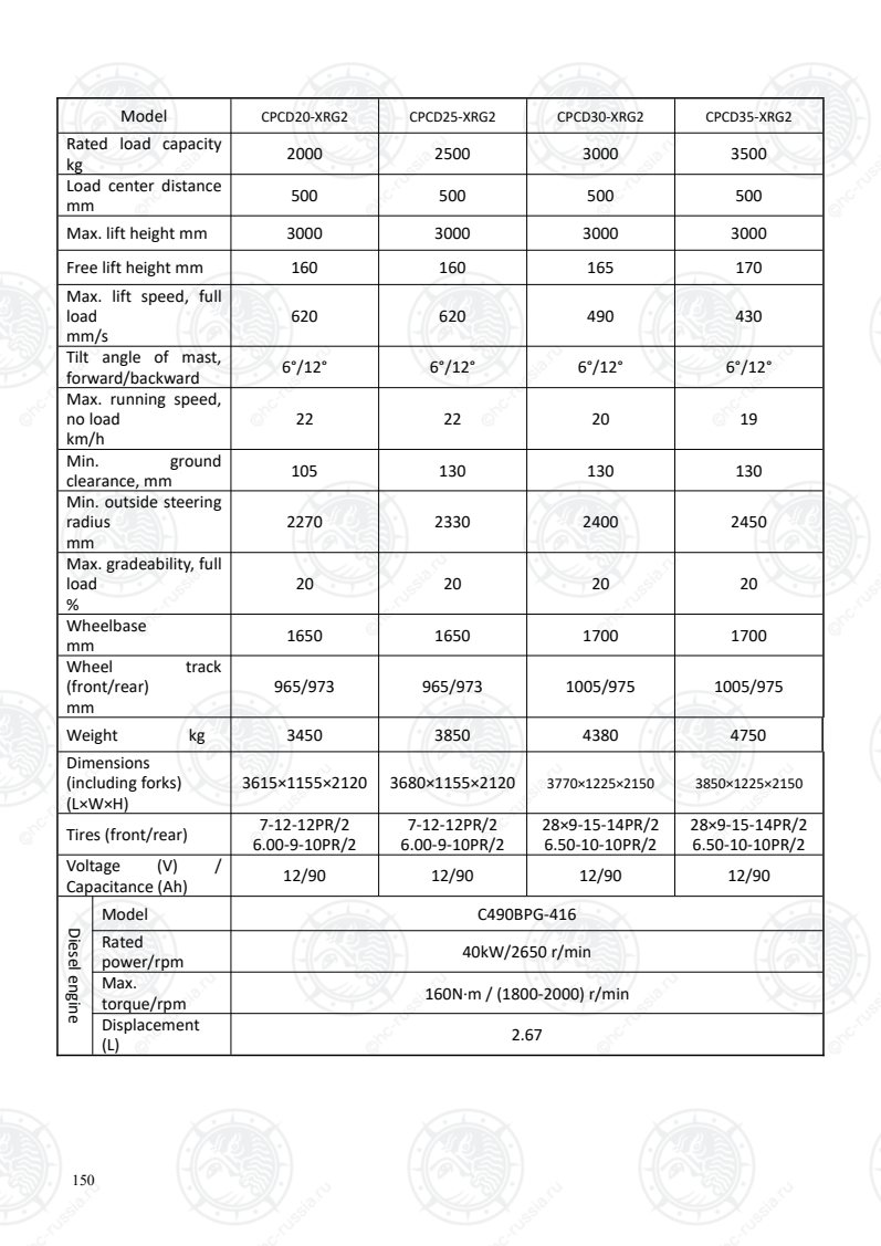
Страница 155
151
Model CPCD38-XRG2
Rated load capacity
kg 3800
Load center distance
mm 500
Max. lift height mm 3000
Free lift height mm 170
Max. lift speed, full
load
mm/s
430
Tilt angle of mast,
forward/backward
(°)
6°/12°
Max. running speed,
no load
km/h
19
Min. ground
clearance, mm 130
Min. outside steering
radius
mm
2480
Max. gradeability,
full load
%
15
Wheelbase
mm 1700
Wheel track
(front/rear)
mm
1005/975
Weight kg 4950
Dimensions
(including forks)
(L×W×H)
3880×1225×2150
Tires (front/rear) 28×9-15-14PR/2
6.50-10-10PR/2
Voltage (V) /
Capacitance (Ah) 12/90
Dieselengine
Model C490BPG-416
Rated
power/rpm 40kW/2650 r/min
Max.
torque/rpm 160N·m / (1800-2000) r/min
Displacement
(L) 2.67
Оригинальная страница: таблицы и схемы
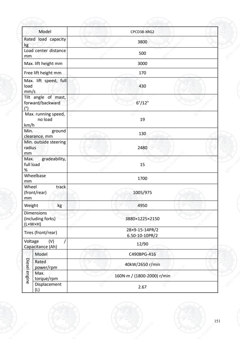
Страница 156
152
4-X5t
Model CPCD40-XRG76 CPCD45-XRG76 CPCD50-XRXG76
Rated load capacity
kg 4000 4500 5000
Load center distance
mm 500 500 500
Max. lift height mm 3000 3000 3000
Free lift height mm 160 160 160
Max. lift speed, full
load
mm/s
440 440 380
Tilt angle of mast,
forward/backward
(°)
6°/12° 6°/12° 6°/12°
Max. running speed,
no load
km/h
25 25 25
Min. ground
clearance, mm 170 170 170
Min. outside steering
radius
mm
2700 2720 2780
Max. gradeability,
full load
%
36 33 31
Wheelbase
mm 2000 2000 2000
Wheel track
(front/rear)
mm
1160/1130 1190/1130 1190/1130
Weight kg 6200 6400 6750
Dimensions
(including forks)
(L×W×H)
4180×1420×2310 4200×1490×2310 4245×1490×2310
Tires (front/rear) 8.25-15-14PR/2
7.00-12-12PR/2
300-15-18PR/2
7.00-12-12PR/2
300-15-18PR/2
7.00-12-12PR/2
Voltage (V) /
Capacitance (Ah) 12/60 12/60 12/60
Dieselengine
Model Yuchai YC4DK90-T304
Rated
power/rpm 66kw / 2200r/min
Max.
torque/rpm 350N·m / (1400-1700) r/min
Оригинальная страница: таблицы и схемы
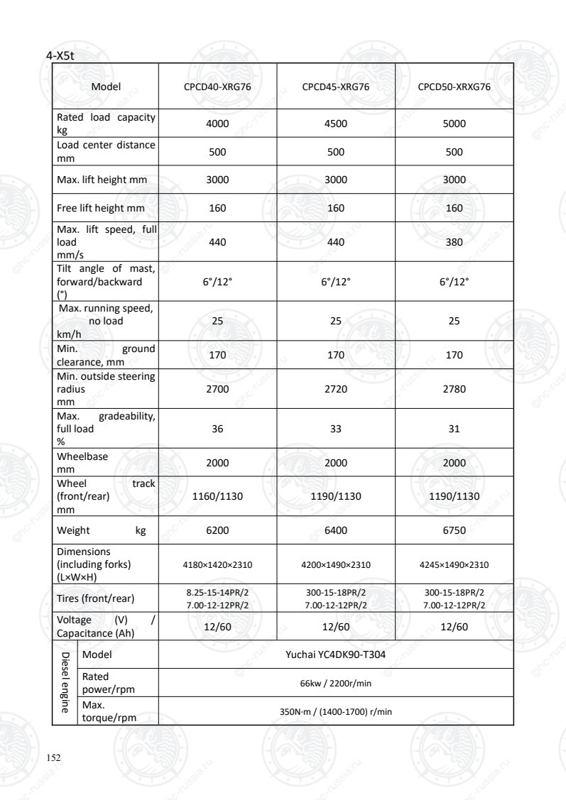
Страница 157
153
Model CPCD40-XRG75 CPCD45-XRG75 CPCD50-XRXG75
Rated load capacity
kg 4000 4500 5000
Load center distance
mm 500 500 500
Max. lift height mm 3000 3000 3000
Free lift height mm 160 160 160
Max. lift speed, full
load
mm/s
440 430 380
Tilt angle of mast,
forward/backward
(°)
6°/12° 6°/12° 6°/12°
Max. running speed,
no load
km/h
25 25 25
Min. ground
clearance, mm 170 170 170
Min. outside steering
radius
mm
2700 2720 2780
Max. gradeability,
full load
%
30 27 25
Wheelbase
mm 2000 2000 2000
Wheel track
(front/rear)
mm
1160/1130 1190/1130 1190/1130
Weight kg 6200 6400 6750
Dimensions
(including forks)
(L×W×H)
4160×1420×2310 4180×1490×2310 4235×1490×2310
Tires (front/rear) 8.25-15-14PR/2
7.00-12-12PR/2
300-15-18PR/2
7.00-12-12PR/2
300-15-18PR/2
7.00-12-12PR/2
Voltage (V) /
Capacitance (Ah) 12/60 12/60 12/60
Dieselengine
Model DCD CY4BG531-2
Rated
power/rpm 60kw / 2200r/min
Max.
torque/rpm 300N·m / (1000-1800) r/min
Оригинальная страница: таблицы и схемы
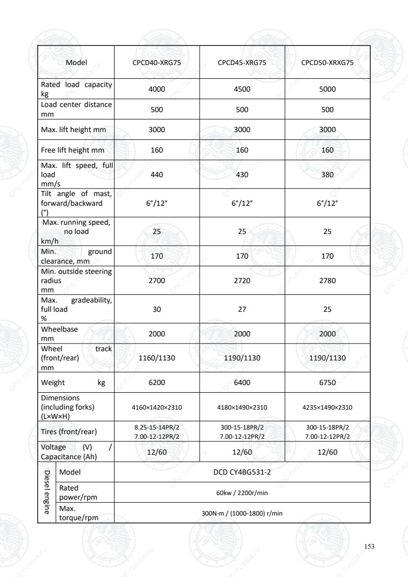
Страница 158
154
Model CPCD40-XRG75-GW CPCD45-XRG75-GW CPCD50-XRXG75-GW
Rated load capacity
kg 4000 4500 5000
Load center distance
mm 500 500 500
Max. lift height mm 3000 3000 3000
Free lift height mm 160 160 165
Max. lift speed, full
load
mm/s
440 440 380
Tilt angle of mast,
forward/backward
(°)
6°/12° 6°/12° 6°/12°
Max. running speed,
no load
km/h
25 25 25
Min. ground
clearance, mm 170 170 170
Min. outside steering
radius
mm
2700 2720 2780
Max. gradeability,
full load
%
30 27 25
Wheelbase
mm 2000 2000 2000
Wheel track
(front/rear)
mm
1160/1130 1190/1130 1190/1130
Weight kg 6200 6400 6750
Dimensions
(including forks)
(L×W×H)
4180×1420×2810 4200×1490×2810 4245×1490×2810
Tires (front/rear) 8.25-15-14PR/2
7.00-12-12PR/2
300-15-18PR/2
7.00-12-12PR/2
300-15-18PR/2
7.00-12-12PR/2
Voltage (V) /
Capacitance (Ah) 24/60 24/60 24/60
Dieselengine
Model DCD CY4BG531-2
Rated
power/rpm 60kw / 2200r/min
Max.
torque/rpm 300N·m / (1400-1800) r/min
Оригинальная страница: таблицы и схемы
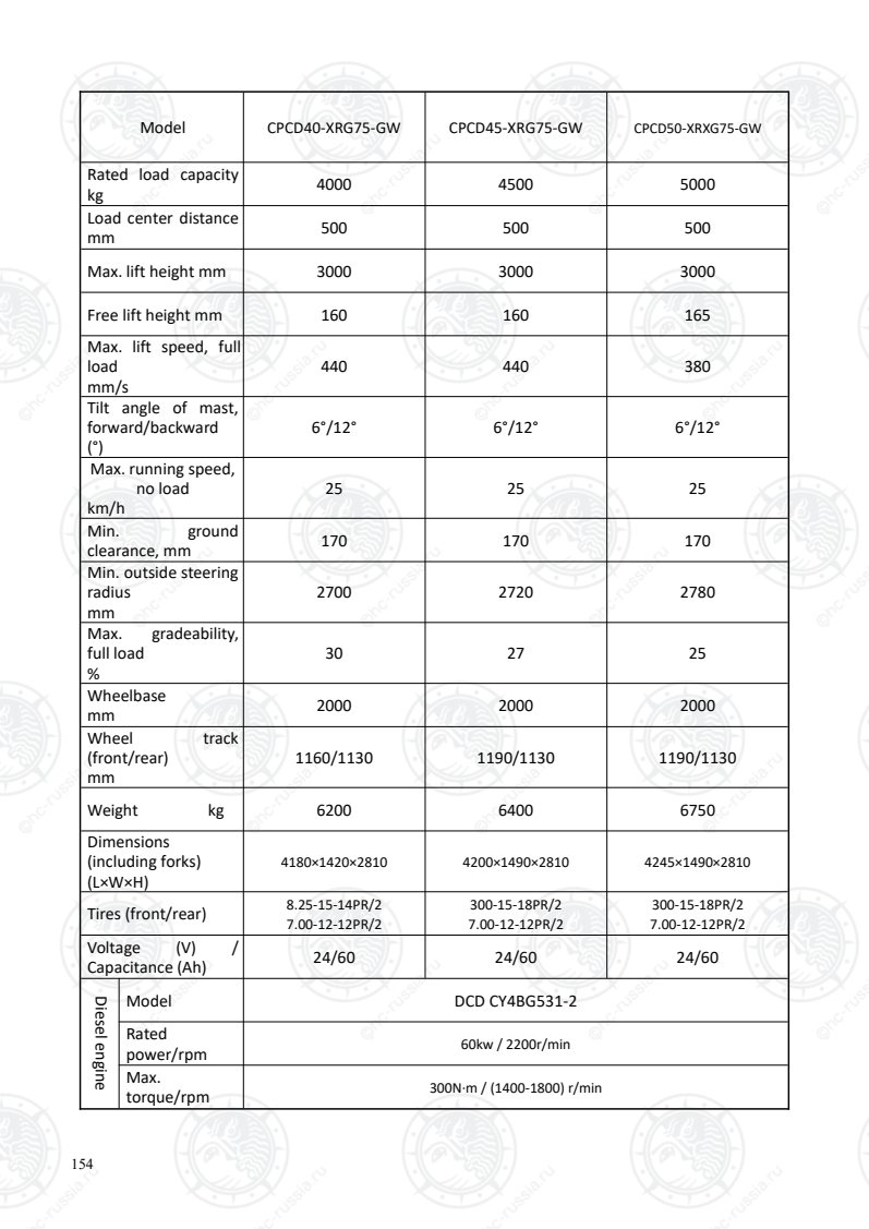
Страница 159
155
Model CPCD40-XRW34 CPCD45-XRW34 CPCD50-XRXW34
Rated load capacity
kg 4000 4500 5000
Load center distance
mm 500 500 500
Max. lift height mm 3000 3000 3000
Free lift height mm 160 160 165
Max. lift speed, full
load
mm/s
440 440 380
Tilt angle of mast,
forward/backward
(°)
6°/12° 6°/12° 6°/12°
Max. running speed,
no load
km/h
25 25 23
Min. ground
clearance, mm 170 170 170
Min. outside steering
radius
mm
2700 2720 2780
Max. gradeability,
full load
%
20 20 20
Wheelbase
mm 2000 2000 2000
Wheel track
(front/rear) mm 1160 / 1130 1190/1130 1190/1130
Weight kg 6150 6350 6700
Dimensions
(including forks)
(L×W×H)
4160×1420×2310 4180×1490×2310 4225×1490×2310
Tires (front/rear) 8.25-15-14PR/2
7.00-12-12PR/2
300-15-18PR/2
7.00-12-12PR/2
300-15-18PR/2
7.00-12-12PR/2
Voltage (V) /
Capacitance (Ah) 12/60 12/60 12/60
Dieselengine
Model Perkins 1004D-44T
Rated
power/rpm 57.5kW/2200 r/min
Max.
torque/rpm 309Nm/1400r/min
Displacement
(L) 4.40
Оригинальная страница: таблицы и схемы
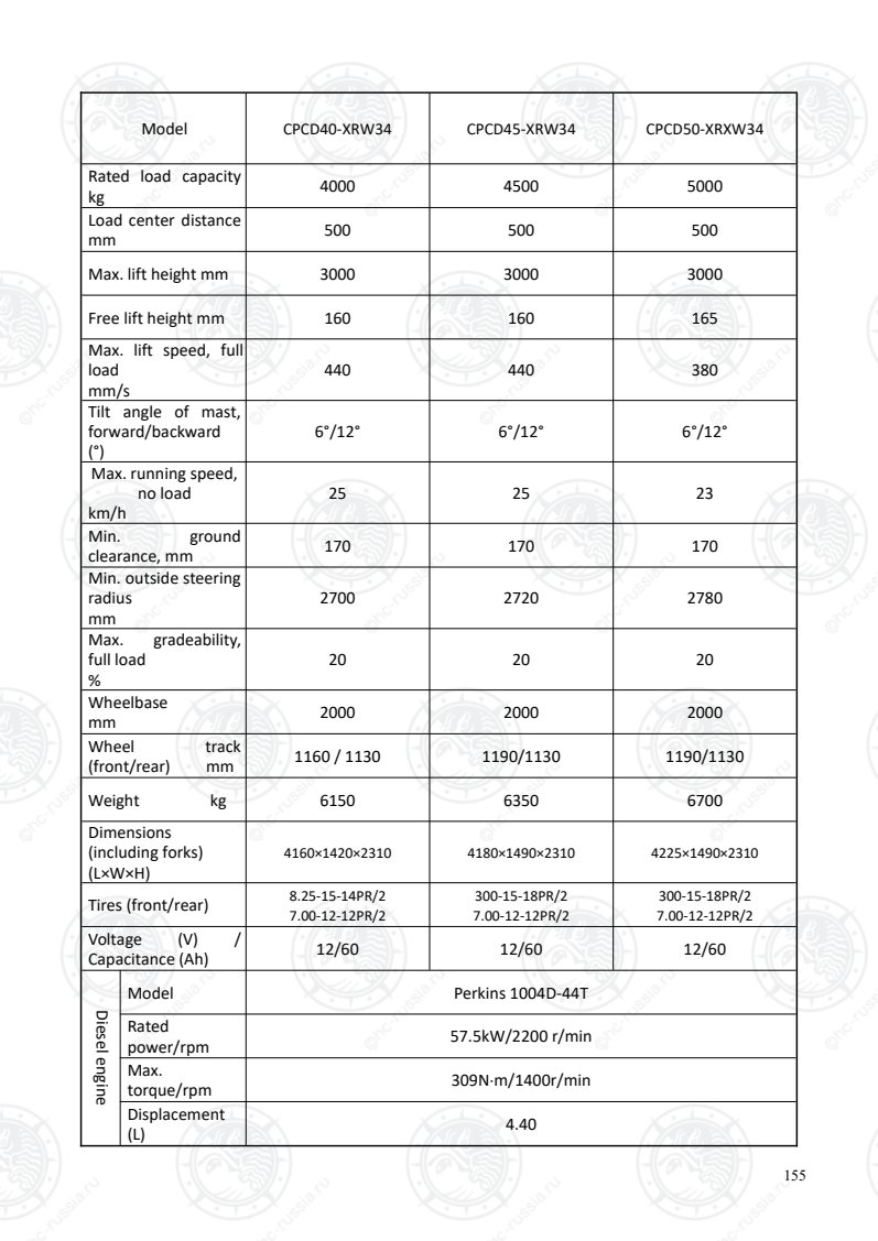
Страница 160
156
Model CPCD40-XRW35 CPCD45-XRW35 CPCD50-XRXW35
Rated load capacity
kg 4000 4500 5000
Load center distance
mm 500 500 500
Max. lift height mm 3000 3000 3000
Free lift height mm 160 160 160
Max. lift speed, full
load
mm/s
440 430 380
Tilt angle of mast,
forward/backward
(°)
6°/12° 6°/12° 6°/12°
Max. running speed,
no load
km/h
24 24 26
Min. ground
clearance, mm 170 170 170
Min. outside steering
radius
mm
2700 2720 2780
Max. gradeability,
full load
%
20 20 20
Wheelbase
mm 2000 2000 2150
Wheel track
(front/rear)
mm
1160/1130 1190/1130 1190/1130
Weight kg 6300 6500 6850
Dimensions
(including forks)
(L×W×H)
4160×1420×2310 4180×1490×2310 4235×1490×2310
Tires (front/rear) 8.25-15-14PR/2
7.00-12-12PR/2
300-15-18PR/2
7.00-12-12PR/2
300-15-18PR/2
7.00-12-12PR/2
Voltage (V) /
Capacitance (Ah) 12/60 12/60 12/60
Dieselengine
Model Perkins 1004D-44
Rated
power/rpm 56kW/2200 r/min
Max.
torque/rpm 265Nm/1700r/min
Displacement
(L) 4.41
Оригинальная страница: таблицы и схемы
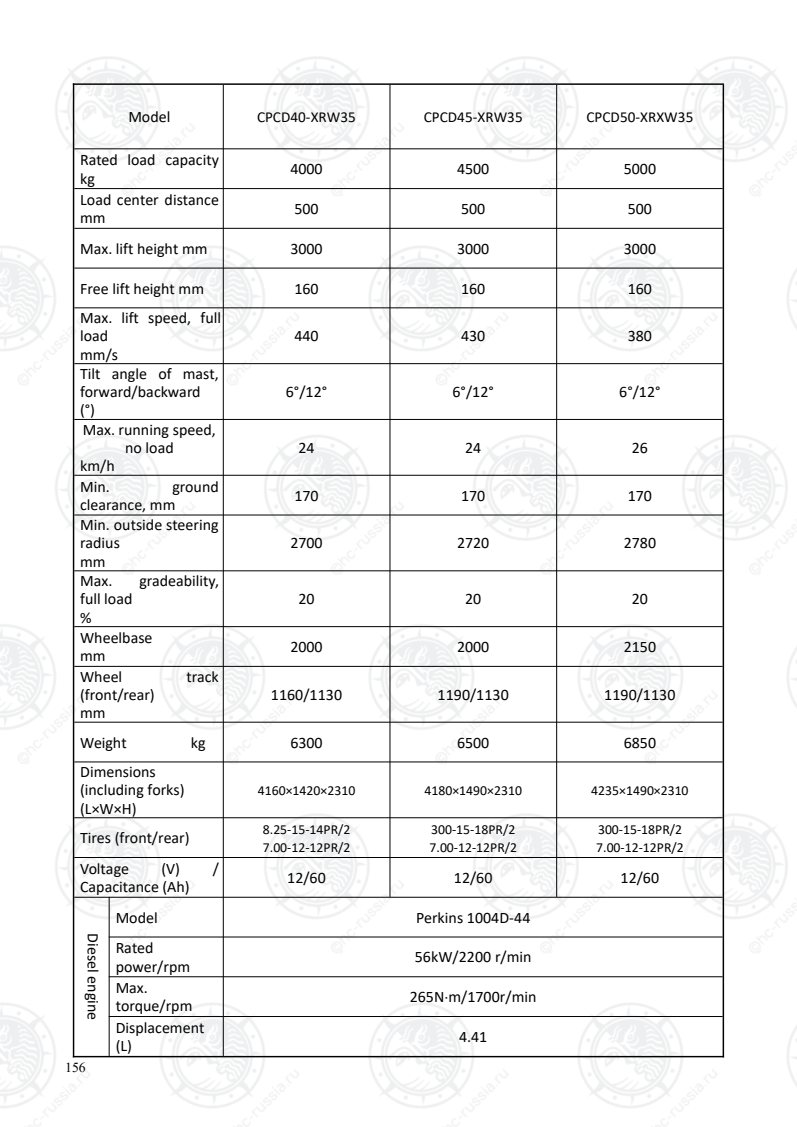
Страница 161
157
Model CPQYD40-XRW57 CPQYD45-XRW57 CPQYD50-XRXW57
Rated load capacity
kg 4000 4500 5000
Load center distance
mm 500 500 500
Max. lift height mm 3000 3000 3000
Free lift height mm 160 160 165
Max. lift speed, full
load
mm/s
460 460 400
Tilt angle of mast,
forward/backward
(°)
6°/12° 6°/12° 6°/12°
Max. running speed,
no load
km/h
25 25 25
Min. ground
clearance, mm 170 170 170
Min. outside steering
radius
mm
2700 2720 2780
Max. gradeability,
full load
%
32 29 27
Wheelbase
mm 2000 2000 2000
Wheel track
(front/rear)
mm
1160/1130 1190/1130 1190/1130
Weight kg 6200 6400 6750
Dimensions
(including forks)
(L×W×H)
4180×1420×2310 4200×1490×2310 4245×1490×2310
Tires (front/rear) 8.25-15-14PR/2
7.00-12-12PR/2
300-15-18PR/2
7.00-12-12PR/2
300-15-18PR/2
7.00-12-12PR/2
Voltage (V) /
Capacitance (Ah) 12/60 12/60 12/60
Dualfuelengine:
Model GM4.3L LX
Rated
power/rpm 74kw / 2300r/min
Max.
torque/rpm 301N·m/ 1700 r/min
Displacement
(L) 4.294
Power type LPG
Оригинальная страница: таблицы и схемы
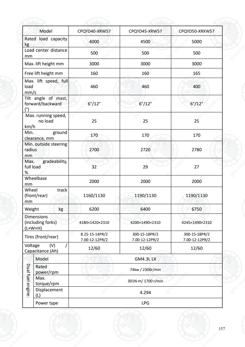
Страница 162
158
Model CPCD40-XRG73 CPCD45-XRG73 CPCD50-XRXG73
Rated load capacity
kg 4000 4500 5000
Load center distance
mm 500 500 500
Max. lift height mm 3000 3000 3000
Free lift height mm 160 160 165
Max. lift speed, full
load
mm/s
440 430 380
Tilt angle of mast,
forward/backward
(°)
6°/12° 6°/12° 6°/12°
Max. running speed,
no load
km/h
25 25 25
Min. ground
clearance, mm 170 170 170
Min. outside steering
radius
mm
2700 2720 2780
Max. gradeability,
full load
%
30 27 25
Wheelbase
mm 2000 2000 2000
Wheel track
(front/rear)
mm
1160/1130 1190/1130 1190/1130
Weight kg 6300 6500 6850
Dimensions
(including forks)
(L×W×H)
4160×1420×2310 4180×1490×2310 4225×1490×2310
Tires (front/rear) 8.25-15-14PR/2
7.00-12-12PR/2
300-15-18PR/2
7.00-12-12PR/2
300-15-18PR/2
7.00-12-12PR/2
Voltage (V) /
Capacitance (Ah) 12/105 12/105 12/105
Dieselengine
Model Xinchai 4D32RG30-001
Rated
power/rpm 60kW/2200 r/min
Max.
torque/rpm 300Nm/ (1600-1800) r/min
Оригинальная страница: таблицы и схемы
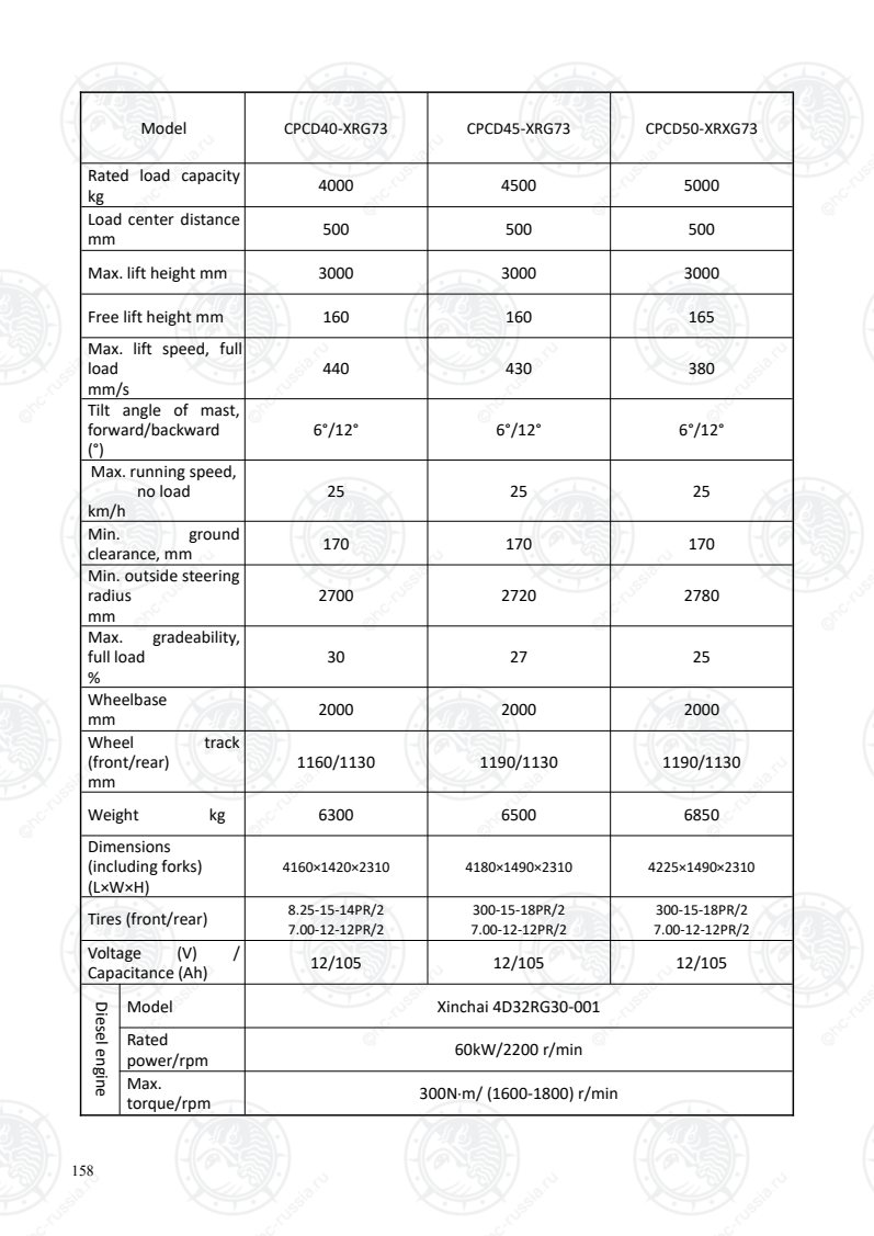
Страница 163
159
Model CPC40-XRG73 CPC45-XRG73
Rated load capacity
kg 4000 4500
Load center distance
mm 500 500
Max. lift height mm 3000 3000
Free lift height mm 160 160
Max. lift speed, full
load
mm/s
440 430
Tilt angle of mast,
forward/backward
(°)
6°/12° 6°/12°
Max. running speed,
no load
km/h
25 25
Min. ground
clearance, mm 170 170
Min. outside steering
radius
mm
2700 2720
Max. gradeability,
full load
%
20 20
Wheelbase
mm 2000 2000
Wheel track
(front/rear)
mm
1160/1130 1190/1130
Weight kg 6300 6500
Dimensions
(including forks)
(L×W×H)
4160×1420×2310 4180×1490×2310
Tires (front/rear) 8.25-15-14PR/2
7.00-12-12PR/2
300-15-18PR/2
7.00-12-12PR/2
Voltage (V) /
Capacitance (Ah) 12/105 12/105
Dieselengine
Model 4D32RG30-002
Rated
power/rpm 50kW/2300 r/min
Max.
torque/rpm 250N·m/(1500-1700) r/min
Оригинальная страница: таблицы и схемы
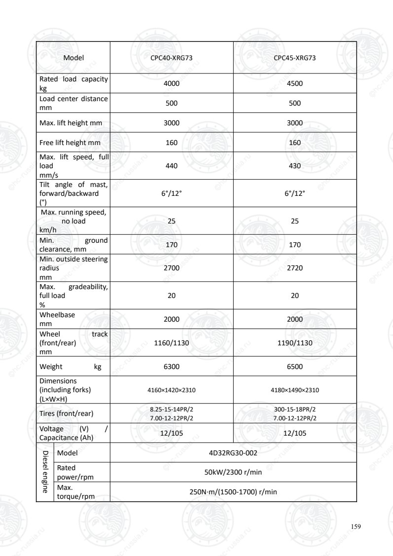
Страница 164
160
Model CPC50-XRXG73
Rated load capacity
kg 5000
Load center distance
mm 500
Max. lift height mm 3000
Free lift height mm 160
Max. lift speed, full
load
mm/s
380
Tilt angle of mast,
forward/backward
(°)
6/12
Max. running speed,
no load
km/h
23
Min. ground
clearance, mm 170
Min. outside steering
radius
mm
2780
Max. gradeability,
full load
%
20
Wheelbase
mm 2000
Wheel track
(front/rear)
mm
1190/1130
Weight kg 6850
Dimensions
(including forks)
(L×W×H)
4225×1490×2310
Tires (front/rear) 300-15-18PR/2
7.00-12-12PR/2
Voltage (V) /
Capacitance (Ah) 12/105
Dieselengine
Model 4D32RG30-001
Rated
power/rpm 60kW/2200 r/min
Max.
torque/rpm 320N·m/(1500-1700) r/min
Оригинальная страница: таблицы и схемы
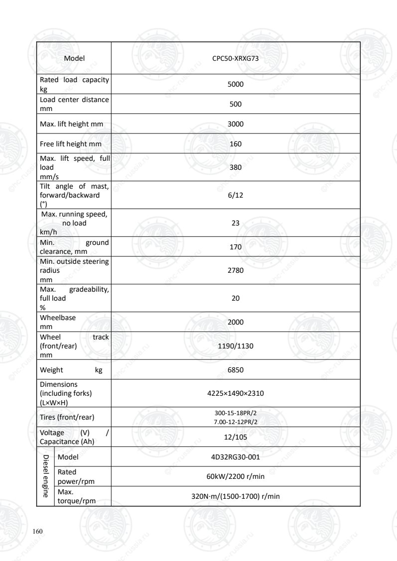
Страница 165
161
Model CPCD55-XRXG73BN-S
Rated load capacity
kg 5500
Load center distance
mm 500
Max. lift height mm 3000
Free lift height mm 165
Max. lift speed, full
load
mm/s
530
Tilt angle of mast,
forward/backward
(°)
9/9
Max. running speed,
no load
km/h
25
Min. ground
clearance, mm 170
Min. outside steering
radius
mm
2880
Max. gradeability,
full load
%
20
Wheelbase
mm 2100
Wheel track
(front/rear)
mm
1190/1130
Weight kg 7200
Dimensions
(including forks)
(L×W×H)
4325×1530×2270
Tires (front/rear) 300-15-18PR/2
7.00-12-14PR/2
Voltage (V) /
Capacitance (Ah) 12/105
Dieselengine
Model 4D32RG30-017
Rated
power/rpm 60kW/2200 r/min
Max.
torque/rpm 320N·m / (1500-1700) r/min
Оригинальная страница: таблицы и схемы
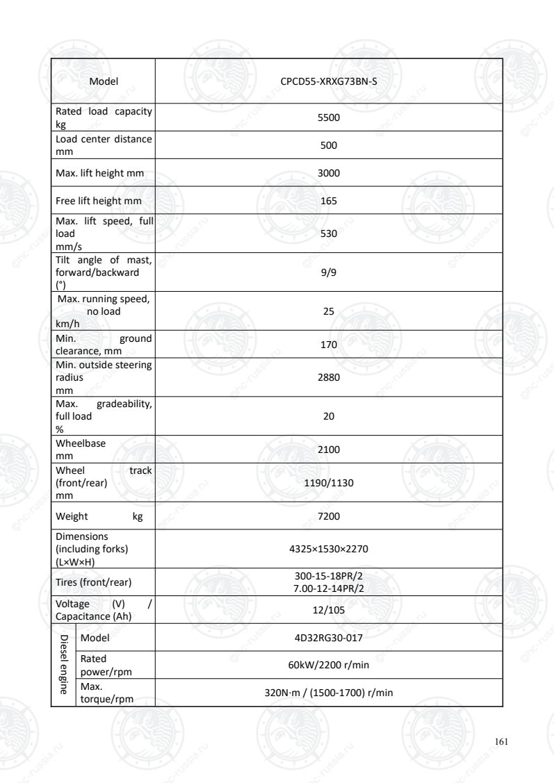
Страница 166
162
Model CPCD40-XRW76 CPCD45-XRW76 CPCD50-XRXW76
Rated load capacity
kg 4000 4500 5000
Load center distance
mm 500 500 500
Max. lift height mm 3000 3000 3000
Free lift height mm 160 160 160
Max. lift speed, full
load
mm/s
460 520 450
Tilt angle of mast,
forward/backward
(°)
6°/12° 6°/12° 6°/12°
Max. running speed,
no load
km/h
26 26 26
Min. ground
clearance, mm 170 170 170
Min. outside steering
radius
mm
2700 2720 2780
Max. gradeability,
full load
%
20 22 20
Wheelbase
mm 2000 2000 2000
Wheel track
(front/rear)
mm
1160/1130 1190/1130 1190/1130
Weight kg 6200 6400 6750
Dimensions
(including forks)
(L×W×H)
4180×1420×2310 4200×1490×2310 4245×1490×2310
Tires (front/rear) 8.25-15-14PR/2
7.00-12-12PR/2
300-15-18PR/2
7.00-12-12PR/2
300-15-18PR/2
7.00-12-12PR/2
Voltage (V) /
Capacitance (Ah) 24/60 24/60 24/60
Dieselengine
Model Mitsubishi SPD-S6S-G3-3 China III
Mitsubishi SPC-S6S-239-1 Euro Ⅲ A
Rated
power/rpm 52kW/2300 r/min
Max.
torque/rpm 248Nm/1700r/min
Оригинальная страница: таблицы и схемы
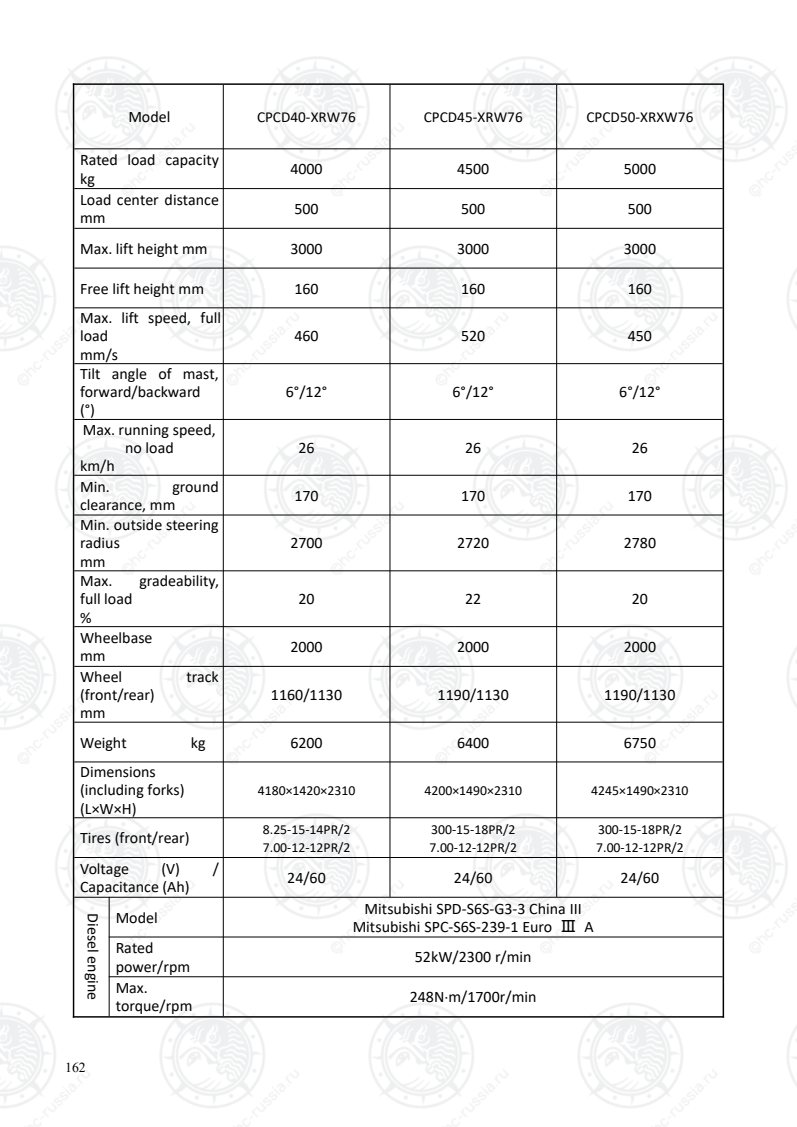
Страница 167
163
Model CPCD40-XRW76BN CPCD45-XRW76BN CPCD50-XRXW76BN
Rated load capacity
kg 4000 4500 5000
Load center distance
mm 500 500 500
Max. lift height mm 3000 3000 3000
Free lift height mm 160 160 160
Max. lift speed, full
load
mm/s
520 520 450
Tilt angle of mast,
forward/backward
(°)
6°/12° 6°/12° 6°/12°
Max. running speed,
no load
km/h
26 26 26
Min. ground
clearance, mm 170 170 170
Min. outside steering
radius
mm
2700 2720 2780
Max. gradeability,
full load
%
25 22 20
Wheelbase
mm 2000 2000 2000
Wheel track
(front/rear)
mm
1160/1130 1190/1130 1190/1130
Weight kg 6200 6400 6750
Dimensions
(including forks)
(L×W×H)
4180×1420×2310 4200×1490×2310 4245×1490×2310
Tires (front/rear) 8.25-15-14PR/2
7.00-12-12PR/2
300-15-18PR/2
7.00-12-12PR/2
300-15-18PR/2
7.00-12-12PR/2
Voltage (V) /
Capacitance (Ah) 24/60 24/60 24/60
Dieselengine
Model Mitsubishi SPD-S6S-G3-3 China III
Mitsubishi SPC-S6S-239-1 Euro Ⅲ A
Rated
power/rpm 52kW/2300 r/min
Max.
torque/rpm 248Nm/1700r/min
Оригинальная страница: таблицы и схемы
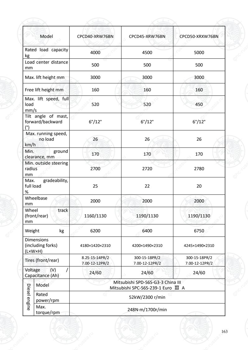
Страница 168
164
Model CPCD40-XRW19 CPCD45-XRW19 CPCD50-XRXW19
Rated load capacity
kg 4000 4500 5000
Load center distance
mm 500 500 500
Max. lift height mm 3000 3000 3000
Free lift height mm 160 160 160
Max. lift speed, full
load
mm/s
460 460 460
Tilt angle of mast,
forward/backward
(°)
6°/12° 6°/12° 6°/12°
Max. running speed,
no load
km/h
26 25 26
Min. ground
clearance, mm 170 170 170
Min. outside steering
radius
mm
2700 2720 2780
Max. gradeability,
full load
%
20 27 20
Wheelbase
mm 2000 2000 2000
Wheel track
(front/rear)
mm
1160/1130 1190/1130 1190/1130
Weight kg 6200 6400 6750
Dimensions
(including forks)
(L×W×H)
4180×1420×2310 4200×1490×2310 4245×1490×2310
Tires (front/rear) 8.25-15-14PR/2
7.00-12-12PR/2
300-15-18PR/2
7.00-12-12PR/2
300-15-18PR/2
7.00-12-12PR/2
Voltage (V) /
Capacitance (Ah) 24/60 24/60 24/60
Dieselengine
Model TD42AA NISSAN
Rated
power/rpm 59kW/2300 r/min
Max.
torque/rpm 254Nm/1800r/min
Оригинальная страница: таблицы и схемы
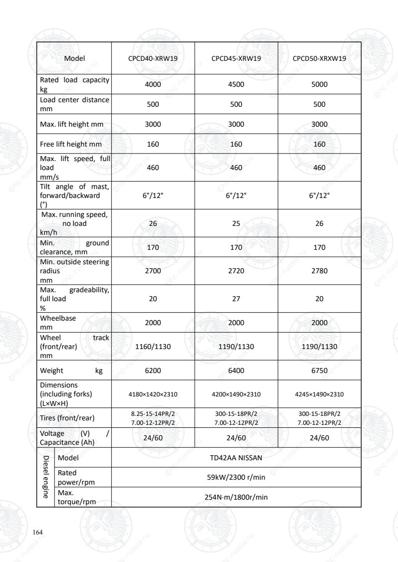
Страница 169
165
Model CPCD40-XRG93 CPCD45-XRG93 CPCD50-XRXG93
Rated load capacity
kg 4000 4500 5000
Load center distance
mm 500 500 500
Max. lift height mm 3000 3000 3000
Free lift height mm 160 160 165
Max. lift speed, full
load
mm/s
440 430 380
Tilt angle of mast,
forward/backward
(°)
6°/12° 6°/12° 6°/12°
Max. running speed,
no load
km/h
25 25 25
Min. ground
clearance, mm 170 170 170
Min. outside steering
radius
mm
2700 2720 2780
Max. gradeability,
full load
%
30 27 25
Wheelbase
mm 2000 2000 2000
Wheel track
(front/rear)
mm
1160/1130 1190/1130 1190/1130
Weight kg 6200 6400 6750
Dimensions
(including forks)
(L×W×H)
4180×1420×2250 4200×1490×2250 4245×1490×2250
Tires (front/rear) 8.25-15-14PR/2
7.00-12-12PR/2
300-15-18PR/2
7.00-12-12PR/2
300-15-18PR/2
7.00-12-12PR/2
Voltage (V) /
Capacitance (Ah) 12/105 12/105 12/105
Dieselengine
Model Xinchai 4D35Y41-003
Rated
power/rpm 55.8kW/2200 r/min
Max.
torque/rpm 320Nm/1600r/min
Emission
standards China IV
Оригинальная страница: таблицы и схемы
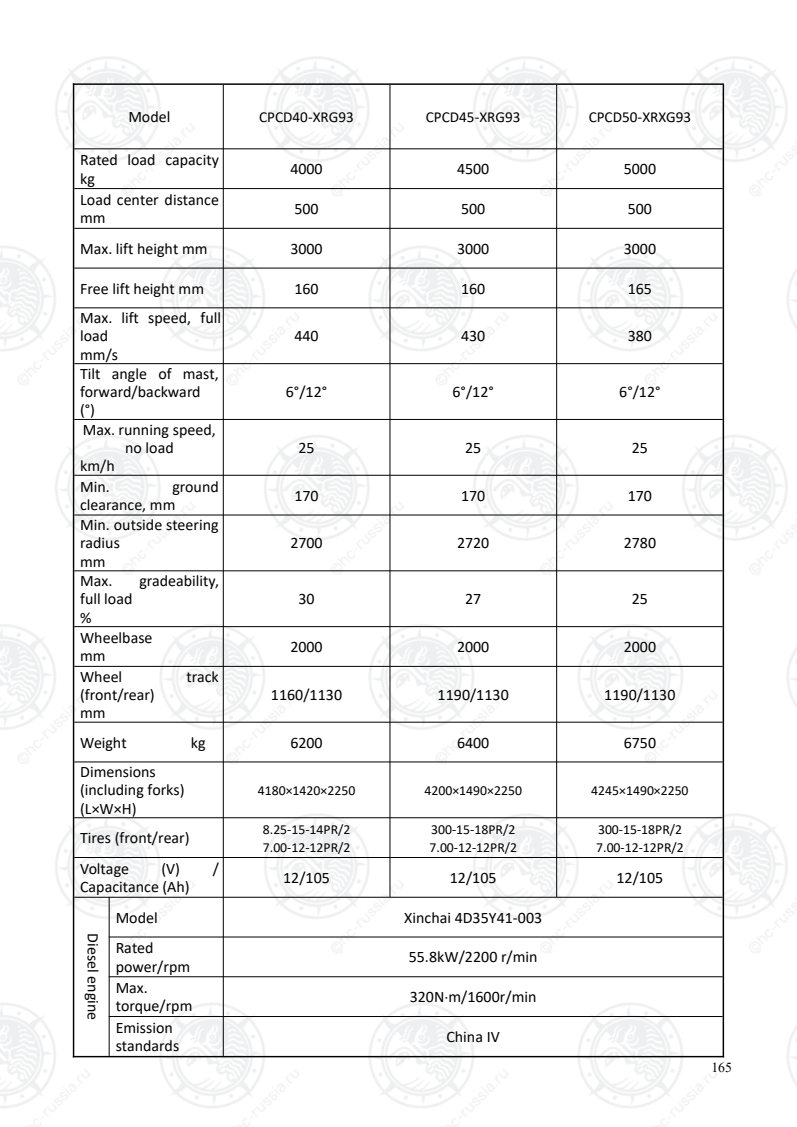
Страница 170
166
Model CPCD40-XRG93-GW CPCD45-XRG93-GW CPCD50-XRXG93-GW
Rated load capacity
kg 4000 4500 5000
Load center distance
mm 500 500 500
Max. lift height mm 3000 3000 3000
Free lift height mm 160 160 165
Max. lift speed, full
load
mm/s
440 440 380
Tilt angle of mast,
forward/backward
(°)
6°/12° 6°/12° 6°/12°
Max. running speed,
no load
km/h
25 25 25
Min. ground
clearance, mm 170 170 170
Min. outside steering
radius
mm
2700 2720 2780
Max. gradeability,
full load
%
30 27 25
Wheelbase
mm 2000 2000 2000
Wheel track
(front/rear)
mm
1160/1130 1190/1130 1190/1130
Weight kg 6200 6400 6750
Dimensions
(including forks)
(L×W×H)
4180×1420×2810 4200×1490×2810 4245×1490×2810
Tires (front/rear) 8.25-15-14PR/2
7.00-12-12PR/2
300-15-18PR/2
7.00-12-12PR/2
300-15-18PR/2
7.00-12-12PR/2
Voltage (V) /
Capacitance (Ah) 12/105 12/105 12/105
Dieselengine
Model Xinchai 4D35Y41-003
Rated
power/rpm 55.8kW/2200 r/min
Max.
torque/rpm 320Nm/1600r/min
Emission
standards China IV
Оригинальная страница: таблицы и схемы
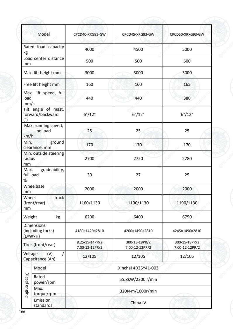
Страница 171
167
Model CPCD40-XRG82 CPCD45-XRG82 CPCD50-XRXG82
Rated load capacity
kg 4000 4500 5000
Load center distance
mm 500 500 500
Max. lift height mm 3000 3000 3000
Free lift height mm 160 160 165
Max. lift speed, full
load
mm/s
440 430 380
Tilt angle of mast,
forward/backward
(°)
6°/12° 6°/12° 6°/12°
Max. running speed,
no load
km/h
25 25 25
Min. ground
clearance, mm 170 170 170
Min. outside steering
radius
mm
2700 2720 2780
Max. gradeability,
full load
%
30 27 25
Wheelbase
mm 2000 2000 2000
Wheel track
(front/rear)
mm
1160/1130 1190/1130 1190/1130
Weight kg 6200 6400 6750
Dimensions
(including forks)
(L×W×H)
4180×1420×2250 4200×1490×2250 4245×1490×2250
Tires (front/rear) 8.25-15-14PR/2
7.00-12-12PR/2
300-15-18PR/2
7.00-12-12PR/2
300-15-18PR/2
7.00-12-12PR/2
Voltage (V) /
Capacitance (Ah) 24/60 24/60 24/60
Dieselengine
Model Yuchai YCF3675-T480
Rated
power/rpm 55.8kW/2200 r/min
Max.
torque/rpm 330Nm/1600r/min
Displacement
(L) 3.621
Emission
standards China IV
Оригинальная страница: таблицы и схемы
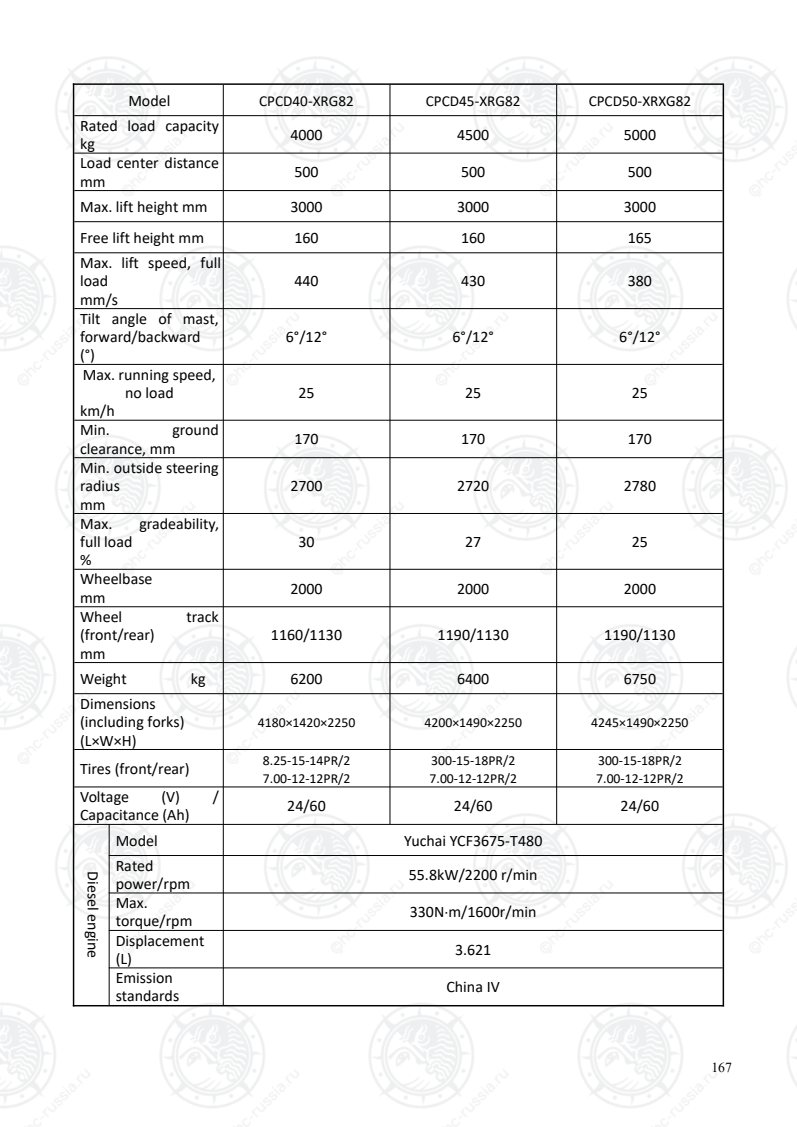
Страница 172
168
Model CPCD55-XRXG76BN-S
Rated load capacity
kg 5500
Load center distance
mm 500
Max. lift height mm 3000
Free lift height mm 165
Max. lift speed, full
load
mm/s
530
Tilt angle of mast,
forward/backward
(°)
9/9
Max. running speed,
no load
km/h
25
Min. ground
clearance, mm 170
Min. outside steering
radius
mm
2880
Max. gradeability,
full load
%
20
Wheelbase
mm 2100
Wheel track
(front/rear)
mm
1190/1130
Weight kg 7200
Dimensions
(including forks)
(L×W×H)
4325×1530×2270
Tires (front/rear) 300-15-18PR/2
7.00-12-14PR/2
Voltage (V) /
Capacitance (Ah) 24/60
Dieselengine
Model YC4DK75-T303
Rated
power/rpm 55kW/2200 r/min
Max.
torque/rpm 315N·m / (1400-1700) r/min
Displacement
(L) 3.621
Оригинальная страница: таблицы и схемы
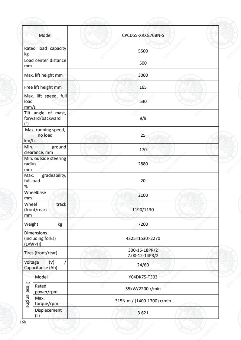
Страница 173
169
Model CPCD55-XRXG82BN-S
Rated load capacity
kg 5500
Load center distance
mm 500
Max. lift height mm 3000
Free lift height mm 165
Max. lift speed, full
load
mm/s
530
Tilt angle of mast,
forward/backward
(°)
9/9
Max. running speed,
no load
km/h
25
Min. ground
clearance, mm 170
Min. outside steering
radius
mm
2880
Max. gradeability,
full load
%
20
Wheelbase
mm 2100
Wheel track
(front/rear)
mm
1190/1130
Weight kg 7200
Dimensions
(including forks)
(L×W×H)
4325×1530×2270
Tires (front/rear) 300-15-18PR/2
7.00-12-14PR/2
Voltage (V) /
Capacitance (Ah) 24/60
Dieselengine
Model Yuchai YCF3675-T480
Rated
power/rpm 55.8kW/2200 r/min
Max.
torque/rpm 330Nm/1600r/min
Displacement
(L) 3.621
Emission
standards China IV
Оригинальная страница: таблицы и схемы
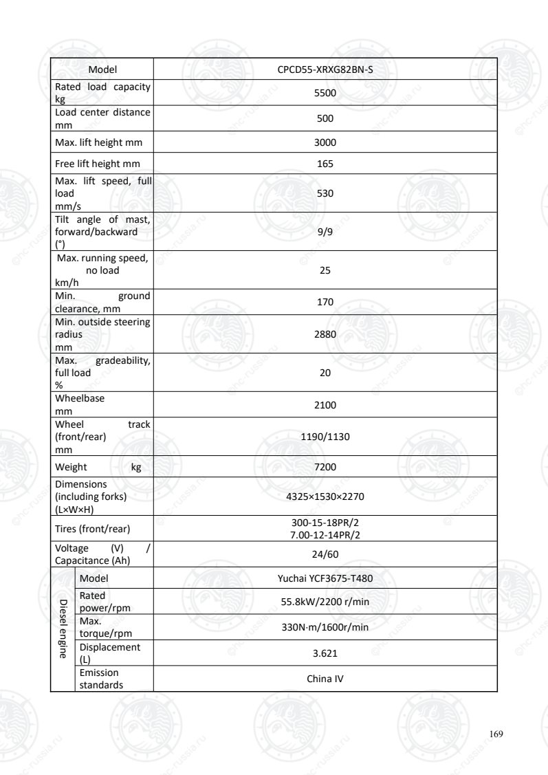
Страница 174
170
XIII. Precautions for using the LPG forklift truck
For the detailed instructions on 1.0t-3.5t single/dual-fuel forklift trucks, please refer to the Operation
and Maintenance Manual for R/XF/X Series 1.5t-3.5t LPG Forklift Trucks
Equipped with USA GM4.3 LX dual-fuel engines
CPYD40-XRW57, CPYD45-XRW57, CPYD50-XRXW57, CPYD55-XRXW57
CPQYD40-XRW57, CPQYD45-XRW57, CPQYD50-XRXW57, CPQYD55-XRXW57
The LPG fuel system mainly consists of a steel cylinder, filter, pressure reducing regulator, and mixer.
LPG enters the pressure reducing regulator from the steel cylinder through the combination valve
and high pressure pipeline via the filter. After vaporization, LPG enters the mixer and mixes with air
in a certain proportion, then enters the engine cylinder for combustion and provides motive power
for the forklift. The GM 4.3L engine is provided with a pressure reducing regulator, mixer and other
LPG elements.
1. LPG filling and replacement
After the fuel in the steel cylinder is used up, it must be replaced. First, close the outlet stop valve,
loosen the quick coupling, cover the outlet joint of the steel cylinder with a dust cap, and remove the
steel cylinder from the truck, and fill it at the gas station. Place the steel cylinder flat during filling,
put the intake limit valve at the upper end (the included angle between the liquid level gauge and
the horizontal line should be 60°), unscrew the dust cover on the filling valve, insert the filling valve,
open the intake limit valve for filling, take out the filling plug when LPG reaches 80% of the steel
cylinder volume (when filling to 80% of rated capacity, the limiting device can be automatically
closed). Pull out the filling plug, screw on the dust cover of the filling valve, and tighten the intake
limit valve when the filling is complete.
Connect the forklift truck line with the quick coupling after installing the steel cylinder at the correct
angle (the included angle between the liquid level gauge and the horizontal line should be about 60°),
open the outlet stop valve switch of the steel cylinder, and check whether there is a gas leak. If a gas
leak is found, the forklift truck can only be started after troubleshooting. Please close the valve on
the steel cylinder after using the forklift truck each time.
2. Operation and use of dual fuel changeover switch
1. If switching to GAS mode, the engine fuel is gasoline.
2. If switching to LPG mode, the engine fuel is LPG.
3. If switching to neutral, neither of the above fuels are
circulating.
3. Starting the dual fuel engine
(1) Start with gasoline
Shut off LPG, turn on the gasoline switch for a few seconds, rotate the ignition key, and start the
motor to run the engine with gasoline.
(2) Start with LPG
① Start without gasoline in the carburetor: If it is known that there is no gasoline in the carburetor
before starting, the engine can be started directly with LPG, i.e. turn off the gasoline switch, turn on
the LPG switch for a few seconds, then turn on the key to start the motor and the engine can run.
② Start with gasoline in the carburetor: It is not easy to start with LPG at this time, so the only way
Оригинальная страница: таблицы и схемы
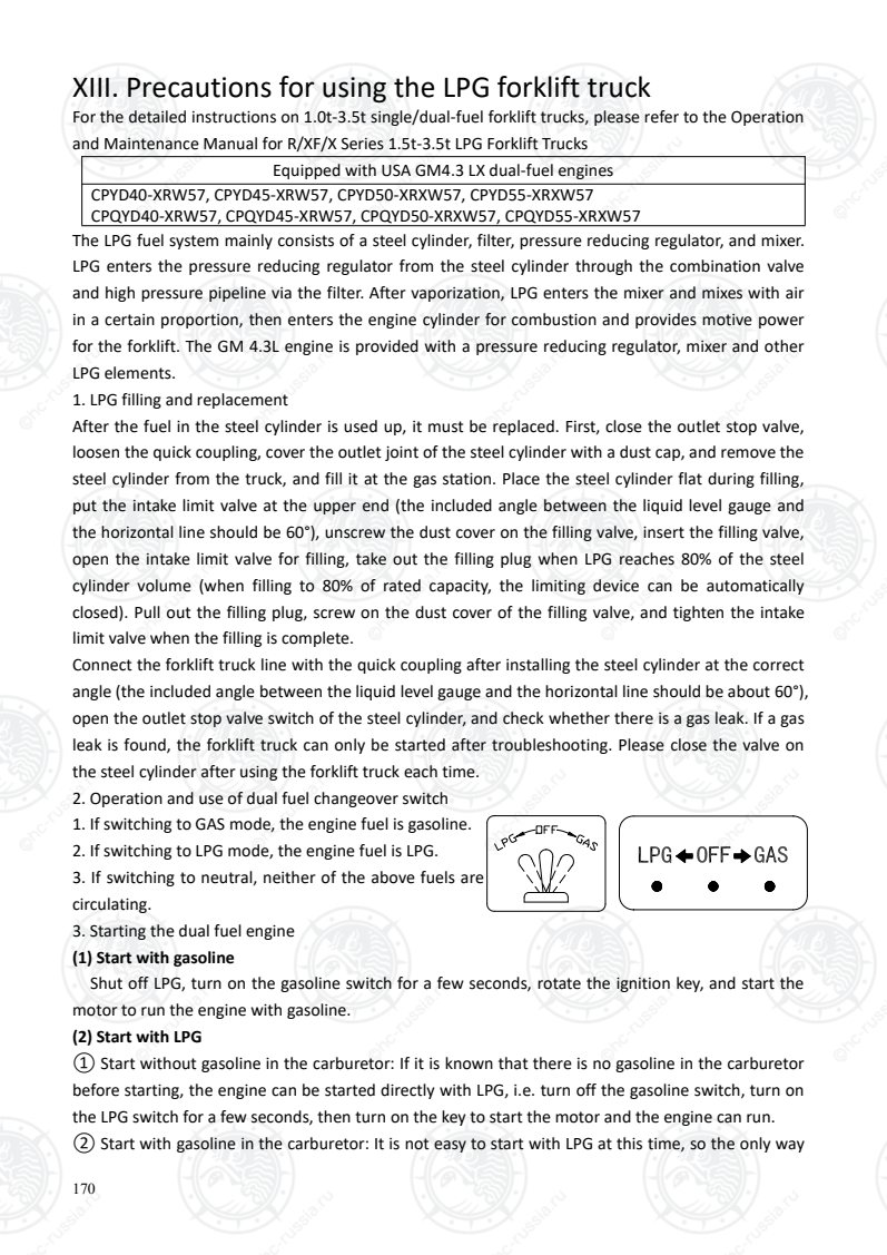
Страница 175
171
is to start the engine with gasoline: turn off the LPG switch and the gasoline switch first (place the
switch to the "OFF" position), and then start the engine with gasoline. When the gasoline in the
carburetor is about to run out and the engine speed becomes low, turn on the LPG switch again and
then start the engine with LPG. Alternatively, after all the gasoline in the carburetor runs out and the
engine stops running, turn on the LPG switch, rotate the key to start the motor, and then the engine
can run.
4. Fuel switching when the engine is running
Switch from LPG to GAS:
① Turn the fuel changeover switch from the "LPG" position to the "OFF" position, depress the
accelerator pedal slightly and hold it still to let the engine accelerate until it stops running.
② After the engine has stopped completely, turn the fuel changeover switch to the "GAS" position
before restarting the engine.
Switch from GAS to LPG:
① Turn the fuel changeover switch from the "GAS" position to the "OFF" position. Depress the
accelerator pedal slightly and hold it still to let the engine accelerate until it stops running.
②After the engine has stopped completely, open the outlet stop valve of the LPG cylinder and turn
the fuel changeover switch to the "LPG" position, and then restart the engine.
Caution
1. Never use the fuel changeover switch to change fuel when the engine is running. Always
remember that it should only be used after the engine has stopped totally.
2. Drive the truck for at least several kilometers with gasoline every two weeks to prevent the
gasoline from degrading.
3. Do not change the fuel used immediately after the engine is started; the engine should be at
normal working temperature before changing the fuel.
Pay special attention to the following points when the forklift truck is running on LPG:
Check whether there is a gas leak in the LPG steel cylinder and pipelines before driving.
Shut down the engine using the following methods after LPG is used:
① Rotate the fuel changeover switch to neutral;
② Let the engine idle until it stops;
③ Ensure that all of the remaining LPG has been used up. Rotate the ignition key switch to “off”
after the engine stops.
4. The outlet stop valve of the steel cylinder should be fully closed and the engine should be
checked for air leakage after use if it is going to be stored for a long time.
5. If air leakage, faults or other abnormalities are found during operation, the outlet stop valve of
the steel cylinder should be closed immediately and professional maintenance personnel should
be sent to check the LPG system.
Оригинальная страница: таблицы и схемы
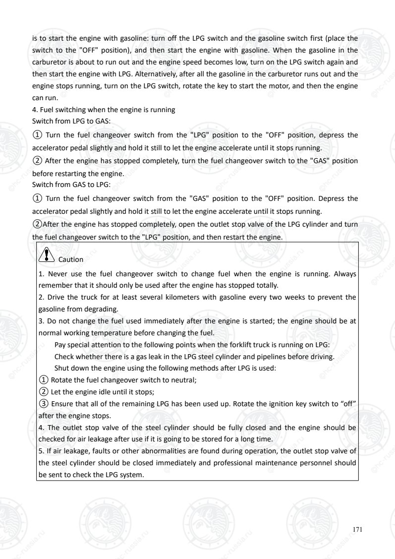
Страница 176
172
5. Precautions
(1) If an LPG leak is found when the forklift truck is in use, the LPG switch should be turned off; the
hydraulic valve should be closed; the pipe joints of device units and fasteners should be checked for
looseness or leakage and promptly dealt with. The truck should be driven using gasoline if the faults
are not eliminated.
(2) Gasoline 93# or vehicle LPG should be used for dual-fuel vehicles; otherwise, the accuracy of
ignition timing will be affected, affecting performance.
(3) When the parking time is more than 10min, the LPG switch (or hydraulic valve) should be closed.
(4) When the engine is running, the water temperature should be 70℃-85℃.
6. Pressure reducing regulator
The pressure reducing regulator has two functions: I. Pressure reducing function. It can reduce the
LPG pressure of the steel cylinder to barometric pressure; II. Evaporation function. LPG can be
vaporized by absorbing the heat circulating in the engine.
7. Mixer
According to the engine running condition, the mixer sends the vaporized LPG mixed with air into the
engine to meet the requirements of the engine.
8. Steel cylinder
(1) Functions
It consists of a safety valve, LPG inlet, outlet quick coupler, and corresponding fittings, it is the fuel
storage supply system for LPG forklift trucks, and is installed at the rear. Main functions are:
a. Stop valve
Hand valve to control inlet and outlet pipes.
b. Filling limit valve
Automatically closed when the LPG quantity reaches 70%-80% of steel cylinder capacity.
c. Liquid level display
Directly displays the liquid level in the steel cylinder.
d. Flow limit valve
Automatically closed when the flow rate is too high (system damage and flow rate exceeding the
design value).
e. Safety valve
When the cylinder pressure exceeds the specified pressure, the safety valve automatically opens
the pressure relief to prevent accidents.
(2) Main parameters
Working temperature: -40℃ to +60℃; working pressure: 2.2MPa; opening pressure of safety valve:
2.5 MPa ± 0.2MPa; maximum filling volume: 80% of steel cylinder volume.
(3) Steel cylinder structure
Оригинальная страница: таблицы и схемы
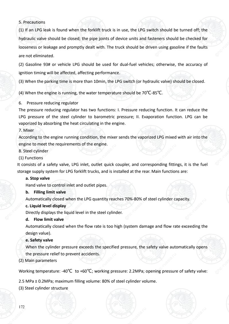
Страница 177
173
1 Filling valve
(filling port and dust cap)
2. Mounting sign
3. Outlet valve (outlet joint) 4. Dowel pin
5. Outlet stop valve 6. Liquid level
gauge
7. Inlet stop valve
(4) Replacement of steel cylinder
Affix the operating instructions for safe use on the steel cylinder (see Fig. 1)
1. Park the truck on flat and solid road, shut down the engine and pull up the hand brake.
2. Remove the steel cylinder:
a. Close the outlet stop valve and loosen the outlet joint. (See Fig. 2)
Fig. 1
 Fig. 2
Оригинальная страница: таблицы и схемы
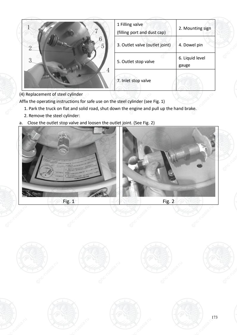
Страница 178
174
b. Loosen the steel cylinder. See the following schematic diagram for specific steps.
Steel belt bracket
Buckle bracket
Buckle and tensioner
1. Hold the tensioner with your right hand
and
pull out the lock catch with your forefinger,
middle finger and ring finger.
2. Continue 1, and push the tensioner up to
press against the steel cylinder
3 Continue to pull out the lock catch and pull
the entire tensioner down hard
Оригинальная страница: таблицы и схемы
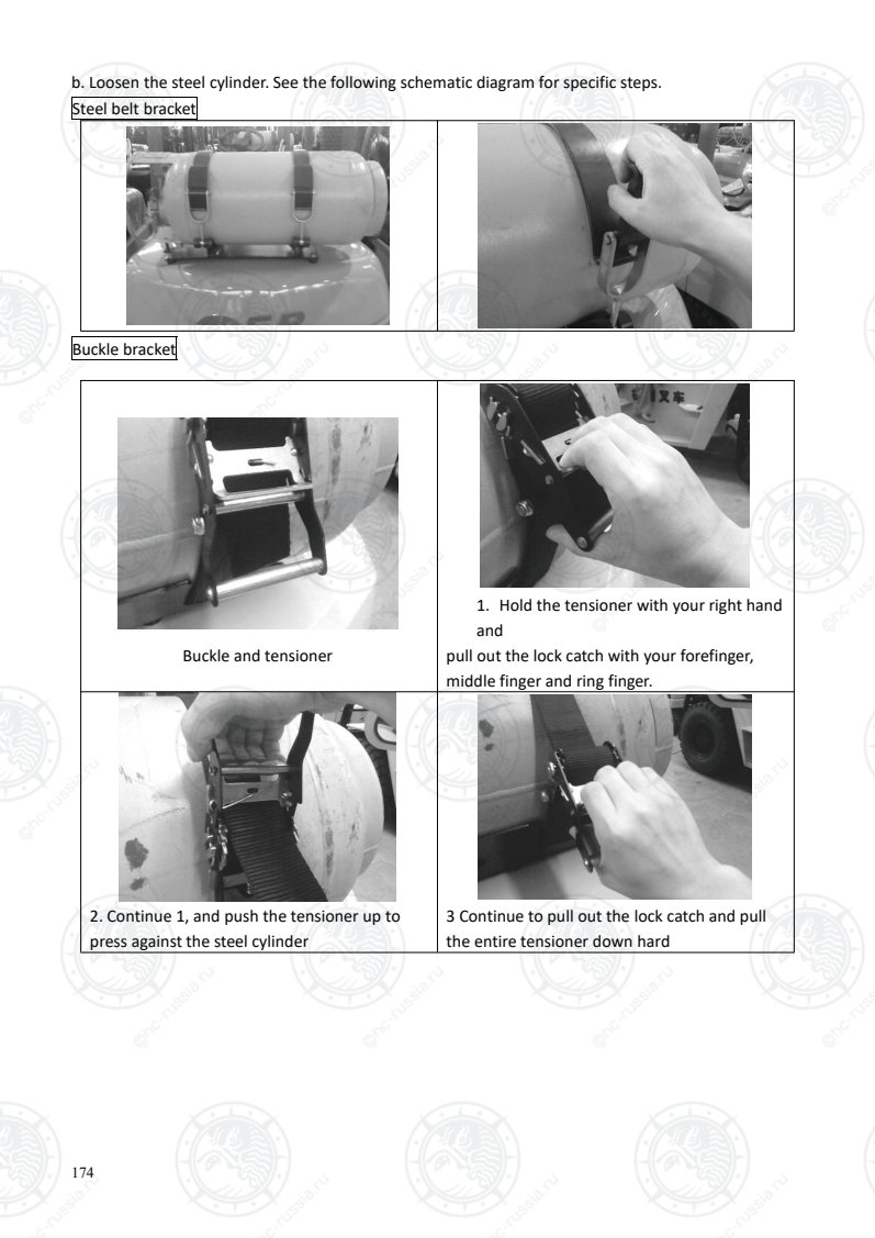
Страница 179
175
4. Release the buckle from the tensioner
5. Release the buckle from the side tensioner
with the same method.
Оригинальная страница: таблицы и схемы
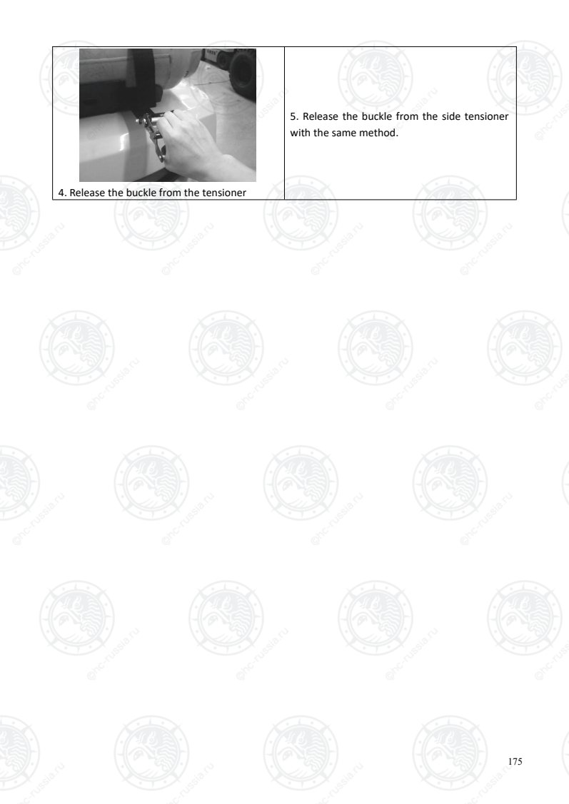
Страница 180
176
Remove the steel cylinder and fill it at a gas station
Notes:
1. Protect the steel cylinder from colliding
against heavy blocks and take care when
lifting, because it is heavy.
2. Ensure that the stop valve at the outlet
end is closed.
3. The steel cylinder has to be filled at a gas
station with an LPG filling permit issued by
the quality and technology supervision
bureau. Do not refill LPG privately; the LPG
needs to conform to the Table 1: Automotive
LPG Technical Requirements.
Note:a) Product No. 1, which can be used at ambient temperature above -20℃;
b) Product No. 2, which can be used at ambient temperature above -10℃;
c) Product No. 3, which can be used at ambient temperature above 0℃.
Оригинальная страница: таблицы и схемы
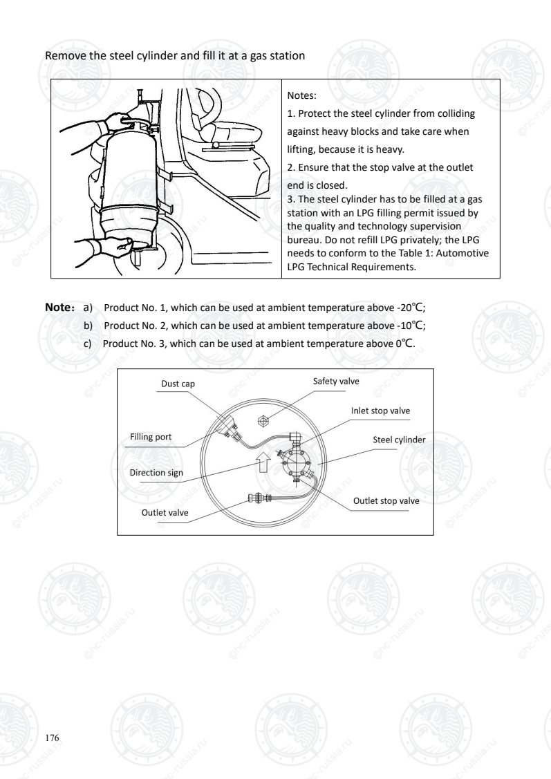
Страница 181
177
Table 1: Automotive LPG Technical Requirements.
Item Quality Index Test Method
No. 1 No. 2 No. 3
Vapor pressure (37.8℃, gauge
pressure) /kPa
≤1430 890 - 1,430 660 - 1340 GB/T 6602a
Conten
t mass
fractio
n/%
Propane >85 >65-85 40 - 65
SH/T 0614b
Butane ≤2.5 — —
Pentane — ≤2.0 ≤2.0
Total olefin ≤10 ≤10 ≤10
Butadiene (1, 3
butadiene) ≤0.5 ≤0.5 ≤0.5
Residu
e
Evaporated residue /
(mL/100mL) ≤0.05 ≤0.05 ≤0.05
SY/T 7509
Oil stain check Pass Pass Pass
Density (20℃)/(kg/m3)
Actual
measureme
nt
Actual
measureme
nt
Actual
measureme
nt
SH/T 0221c
Copper corrosion/grade ≤1 ≤1 ≤1 SH/T 0232
Total sulphur content / (mg/m3) <270 <270 <270 SH/T 0222d
Hydrogen sulfide None None None SH/T 0125
Free water None None None Visual
inspection
Note 1: The total sulfur content is the gaseous sulfur content at 0°C and 101.35 kPa.
Note 2: Check whether there is any free water in the specimen by visual inspection while
measuring the density.
a. The evaporation pressure can be calculated as per GB/T 12576, but subject to the GB/T 6602 in
case of arbitration.
b. The content can be measured as per SH/T 0230, but subject to SH/T 0614 in case of
arbitration.
c. The density can be measured as per GB/T 12576, but subject to the SH/T 0221 in case of
arbitration.
d. The total sulphur content can be measured as per SY/T 7508, but subject to the SH/T 0222 in
case of arbitration.
Source: National Standard of the People's Republic of China: Automotive liquefied petroleum gas
Оригинальная страница: таблицы и схемы
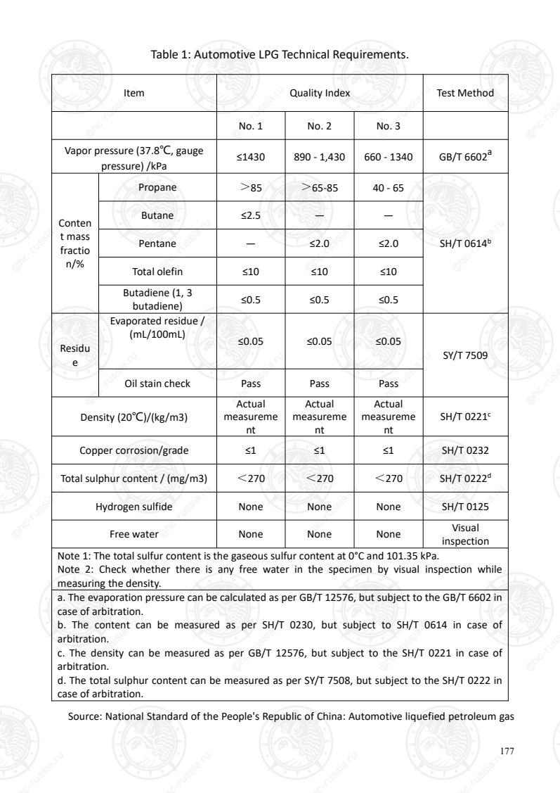
Страница 182
178
(GB 19159-2003)
9. Operation steps for LPG cylinder replacement
(1) You must wear canvas gloves when refilling with gas to protect yourself from frostbite caused
by evaporation of leaked gas.
(2) You should refill gas in a ventilated and empty space, should not smoke, and should avoid
other naked flames.
(3) When filling with LPG, you should place the steel cylinder flat, put the intake stop valve at the
upper end, unscrew the dust cover on the intake stop valve, insert the filling plug, open the
intake stop valve for filling, and take out the filling plug when the LPG quantity reaches 80% of
steel cylinder volume (when filling to 80% of rated capacity, the limit device will be automatically
closed). Pull out the filling plug, screw on the filling valve dust cover, and tighten the intake limit
valve when the charge stops. Check whether the components of each part are in good
condition.
(4) Lift the steel cylinder on the truck and fix the cylinder firmly with arrow ① pointing up. Insert the
dowel pin into the steel cylinder.
(5) Ensure that the inlet and outlet stop valves ②③ are closed.
(6) Connect the forklift truck inlet ⑤ with the outlet valve and fasten them.
(7) Slowly open the outlet stop valve ③.
(8) Use the cylinder after confirming that there is no leakage, close the outlet stop valve ③
immediately if there is any leakage, and unscrew the inlet ⑤ of the forklift truck.
Note: Connect the pipelines with the quick coupling after mounting the steel cylinder, open the outlet
stop valve ③, apply soap bubbles to each pipe joint to check for any leakage, if any leakage is found,
the forklift truck can only be started after troubleshooting. Please close the outlet stop valve ③ each
time after using the forklift truck.
Оригинальная страница: таблицы и схемы
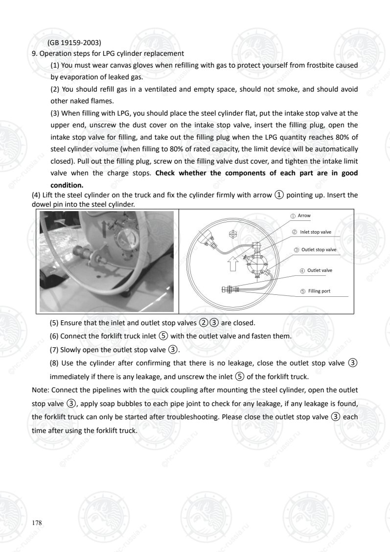
Страница 183
179
10. Steel cylinder mounting method:
Steel belt bracket
Steel belt fixation methods are the reverse of
the disassembly steps
Buckle bracket
a) Hold the tensioner with your
right hand and carry the buckle with
your left hand
Align with the ratchet shaft slots
b. Insert the buckle into the ratchet shaft
slots
c. Pull down the buckle tightly with your left
hand, pull out the lock catch with your
forefinger, middle finger and ring finger of your
right hand, and push up it to press against the
steel cylinder at the same time.
d. Tighten the buckle, keep the lock catch
pulled out, and continue to rotate the
tensioner downward with your right hand until
it presses against the steel cylinder.
Оригинальная страница: таблицы и схемы
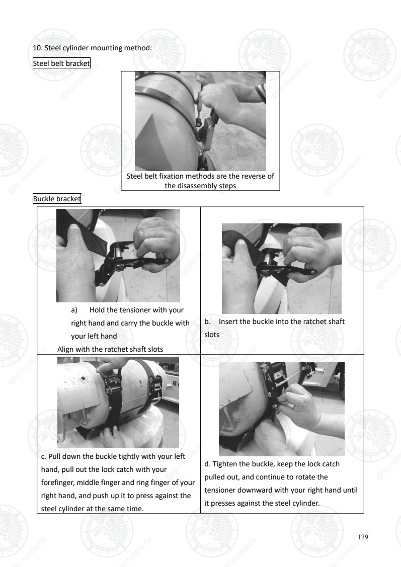
Страница 184
180
e. Continue to tighten with your left hand,
hold the tensioner with your right hand,
release the lock catch, and rotate the
tensioner upward and downward several times
until it cannot be moved.
f. Pull it down to press against the steel
cylinder.
11. Precautions for use
(1) Open the stop valve at the intake end first and close the stop valve at the outlet end when the
assembly is filled with LPG; close the stop valve at the intake end after filling.
(2) The assembly should be installed firmly on the truck; the direction arrow on the end surface of
the steel cylinder should point up; the stop valves at the intake and outlet ends should be closed.
Connect the interface at the input end of the forklift truck with that at the outlet end of the
assembly, screw them in, open the stop valve at the outlet end, and check whether there is any
leakage.
(3) Check for leakage when filling with LPG and every time the truck is used.
(4) Prevent dust ingress at the gas inlet of the intake end and rotate the dust cover straight after
filling with LPG to ensure the gas inlet check valve is tight.
(5) The opening pressure of the safety valve has been factory set and should not be changed
without permission.
(6) In case of any problem, it must be overhauled by a qualified organization, and should not be
adjusted, dismantled and repaired without permission. Faulty steel cylinders should be stored
separately.
(7) The assembly can be filled with LPG in two ways: the volume method and the gravity method.
If the gravity method is used for filling, the steel cylinder needs to be placed vertically; if the
volume method is used for filling, the steel cylinder needs to be placed flat with the direction sign
pointing up.
(8) Filling, transport, storage, use and inspection of the steel cylinder should be in strict
accordance with <Italic>Cylinder Safety Supervision Regulations</Italic> issued by the national
administration of quality and technology supervision
(9) Steel cylinders must be gently assembled and disassembled and should not collide against
each other or be subject to other external impacts. Steel cylinder combination components
should be in good condition and should not be dismantled, adjusted or replaced without
Оригинальная страница: таблицы и схемы
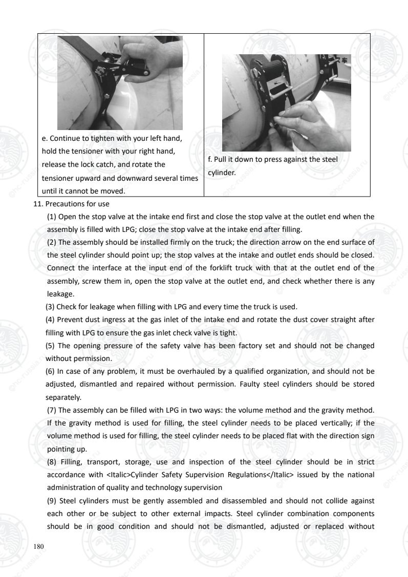
Страница 185
181
permission.
(10) The steel cylinder can be filled with LPG in accordance with GB11174; the maximum filling
quantity should be no more than 80% of the steel cylinder volume.
(11) Steel cylinders must be filled at gas stations with an LPG filling permit issued by the quality
and technology supervision bureau. Filling without permission is prohibited;
(12) When a new steel cylinder or refurbished steel cylinder is used for the first time, the filling
station should conduct vacuum or nitrogen displacement treatment;
(13) Before reinstallation, the steel cylinder should be positioned according to the vertical
installation mark on cylinder, and placed flat; the outlet stop valve should be closed; the intake
stop valve should be opened. Check whether the liquid level gauge pointer rises with the liquid
level synchronously when filling. Stop filling immediately and check whether the liquid level
gauge pointer is in the normal position if the limit valve activates. The intake stop valve has to be
closed after filling.
(14) Check for leakage and other abnormalities before using the steel cylinder, defective steel
cylinders should not be used.
(15) If an LPG leak is found when the forklift truck is in use, the LPG switch should be
disconnected; the outlet stop valve should be closed; the pipe joints of device units and
fasteners should be checked for looseness or leakage and promptly dealt with.
(16) When the parking time is more than 10min, the outlet stop valve should be closed.
(17) The steel cylinder should be kept away from exposure to the sun, heat sources and naked
flames. The steel cylinder must not be heated above 40℃.
(18) The gas in the steel cylinder should not be completely depleted and the remaining gas
should be no less than 0.5% of the specified filling quantity.
(19) Do not change the steel stamp and color mark of the steel cylinder without permission.
(20) The steel cylinder must be delivered to an inspection organization with a pressure vessel
safety supervision organization approval qualification for regular inspection every five years
according to the specified inspection date.
(21) Changes in the steel cylinder gas volume should be monitored when the forklift truck is in
use; if the gas consumption is found to be inconsistent with working hours, the truck should be
stopped to check whether there is a gas leakage; if gas leakage is found, the power supply and
valves should be disconnected and closed immediately and remedial measures should be taken
at once.
(22) The forklift truck should be stopped in a cool and ventilated place, steel cylinder valves should
be closed, and the steel cylinder should be kept away from exposure to the sun.
(23) The power supply and valves should be disconnected and closed when the forklift truck enters
the garage, which should be well ventilated and provided with fire fighting facilities.
(24) Do not repair the LPG steel cylinder, valves or pipes in the garage or parking lot; the driver
should not smoke in the truck.
Оригинальная страница: таблицы и схемы
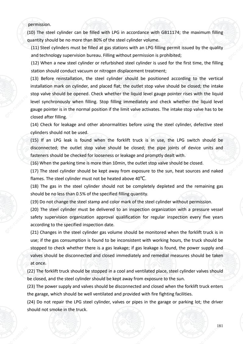
Страница 186
182
12. Maintenance and repair
1. The forklift truck passed the pressure test and quality inspection when leaving the factory; if
any quality problem arises during use, repair without permission is prohibited.
2. The outlet stop valve of the steel pipe should be closed before disassembly and repair of the
LPG device.
3. The gas consumption of the forklift truck may vary with the seasons and the mixer should be
regulated properly.
4. The air cleaner and LPG cleaner need to be checked and cleaned frequently and should be
replaced promptly in case of any damage. The air cleaner element should be cleaned frequently.
5. After assembly, debugging of the LPG forklift truck or at the end of a working day (or use of a
cylinder of gas), the pressure reducing regulator has to be regulated to ensure the proper air-fuel
ratio.
6. The connections of the electric appliance switch system should be checked for oxidization and
rust after being used for three months; if any is found it should be removed immediately.
7. Regular maintenance should be conducted for the complete LPG fuel system after being used
for a year; maintenance content includes cleaning of the pressure reducer and a check of high
pressure and low pressure gas pipe joints for tightness.
Оригинальная страница: таблицы и схемы
Страница 187
183
IMPCO, LPG Fuel System Diagram
Оригинальная страница: таблицы и схемы
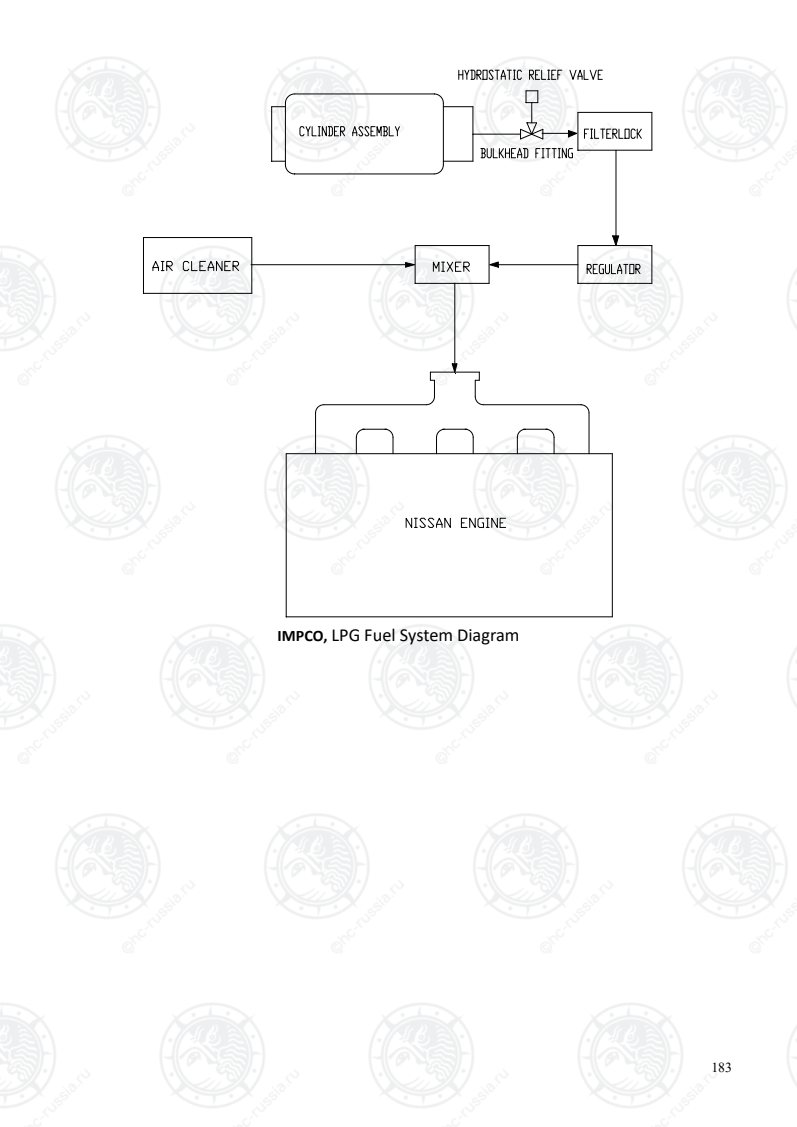
Страница 188
184
GM4.3L, LPG Fuel System Diagram
Оригинальная страница: таблицы и схемы
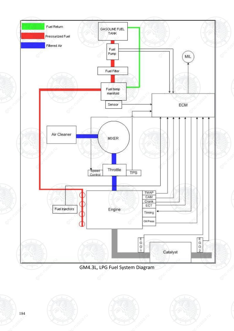
Страница 189
185
XIV. Usage and maintenance methods for the lead-acid
battery
I. Lead-acid battery and use
The battery is used as the power source to start the engine, and it is used as the power supply of the
voltage regulator and overload generators. Light weight, low failure rate, easy to use and maintain. All
batteries are sealed except for maintenance-free batteries which are provided with two vents (to
release gas produced by the battery) on both sides. The lead-acid battery is provided with a filling hole
on the upper cover of battery.
II. Battery storage and handling
① Batteries should be stored in a dry and ventilated place at temperature of 5℃-40℃, kept
away from children and fireworks, kept away from exposure to the sun, radiation and other heat
sources, and out of the rain.
② Batteries should not be stored in more than 4 layers; each layer should be separated by
cardboard to avoid damaging battery pole column.
③ Be gentle when handling batteries; do not tilt, invert, throw, or crush batteries and protect
them from severe impacts to avoid battery leakage and damage.
④ When batteries are provided with a lifting rope or lifting handle, these should be carefully
checked for security before handling; do not repeatedly sway when handling to prevent the lifting
rope or lifting handle from detaching, causing battery to fall.
Caution
Batteries that have been put aside for a long time or are not frequently used should be
maintained regularly and their charging conditions should be checked.
Maintenance-free batteries should be maintained every three months.
Standard lead-acid batteries should be maintained once a month.
III. Battery inspection and maintenance
If the truck has been continuously running, it should be stopped for at least 30 minutes before
checking and disassembling the batteries.
① Check whether the battery case has cracks, damage or electrolyte leakage.
② Do not let the batteries become too discharged; charge promptly when the voltage is lower
than 12.5V.
③ The power level indicator displays battery status after the batteries are installed.
④ Ensure that battery terminal is not corroded, the connecting parts are not loose, there is no
external cracking and the fixing clamp is not loose.
Оригинальная страница: таблицы и схемы
Страница 190
186
3.1 Maintenance-free batteries without power level indicator: The user does not need to add water
and liquid during use.
3.2 Maintenance-free batteries with power level indicator: The user needs to add some water and
liquid during use.
3.2.1 Battery inspection
When the battery capacity status is normal and the electrolyte density reaches the standard, the
observation window shows green. When the battery capacity is insufficient, and the density of the
electrolyte is reduced, the observation window shows white. If the observation window shows red, it
indicates a serious shortage of electrolyte, and the case should be carefully checked for cracking,
leakage or battery failure.
1. Green: Sufficiently charged.
2. White: Insufficiently charged.
3. Red: Replace battery.
See tips on the battery label for details about battery display state.
3.2.2 Battery inspection
1) Ensure that the built-in capacity display (observation window) is green;
2) Disconnect the battery negative ground strap to prevent battery discharge due to additional current
drain;
3) When batteries cannot be removed from the truck, they should be kept fully charged;
4) A regular schedule should be formulated and batteries should be charged once every 30-45 days.
5) When the green state is not visible through the observation window, batteries should be checked
and charged, distilled water should be supplemented or the batteries should be replaced.
3.3 Standard lead-acid battery: The user should keep an eye on the liquid level during use so water
can be added as required.
3.3.1 Battery inspection
As the ambient temperature around the forklift truck is high, batteries consume water easily; please
keep an eye on liquid level during use; there is a filling hole on the upper cover of the battery; when
the liquid level is lower than minimum level, please add distilled water to the upper level; do not
overfill or the liquid will overflow and corrode the truck.
Оригинальная страница: таблицы и схемы
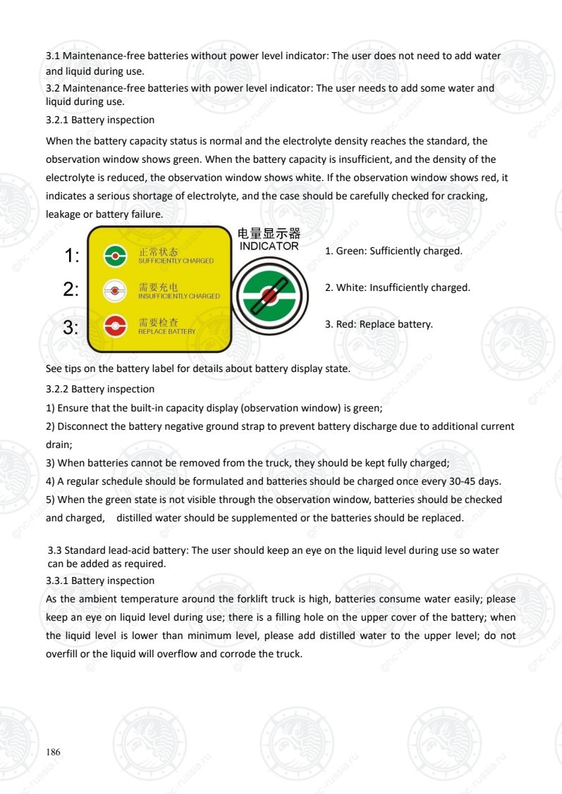
Страница 191
187
Check and confirm whether the liquid level
is between "UPPER LEVEL“ and "LOWER
LEVEL"
1: "UPPER LEVEL"
2: "LOWER LEVEL"
If the liquid level is at or lower than “Lower
Level”, distilled water should be added.
When the electrolyte level is found to be seriously insufficient, the case should be carefully checked
for cracking, leakage or battery failure.
When the battery capacity status is normal and the electrolyte density reaches the standard, the
observation window shows green. When the battery capacity is insufficient, and the density of the
electrolyte is reduced, the observation window shows white. If the observation window shows red, it
indicates a serious shortage of electrolyte, and the case should be carefully checked for cracking,
leakage or battery failure.
See the tips on the battery label for details about battery display state.
3.3.2 Battery maintenance
1) Ensure that the battery electrolyte is at the UPPER LEVEL.
2) Disconnect the battery negative ground strap to prevent battery discharge due to additional current
drain;
3) When batteries cannot be removed from the truck, they should be kept fully charged;
4) A regular schedule should be formulated and batteries should be charged once every 30-45 days.
5) When the battery electrolyte is below the LOWER LEVEL, please add distilled water to the UPPER
LEVEL, and put the vent plug back to the original position, and tighten it.
Caution
Avoid overfilling when adding distilled water. Overflow when refilling batteries may cause
corrosion.
Оригинальная страница: таблицы и схемы
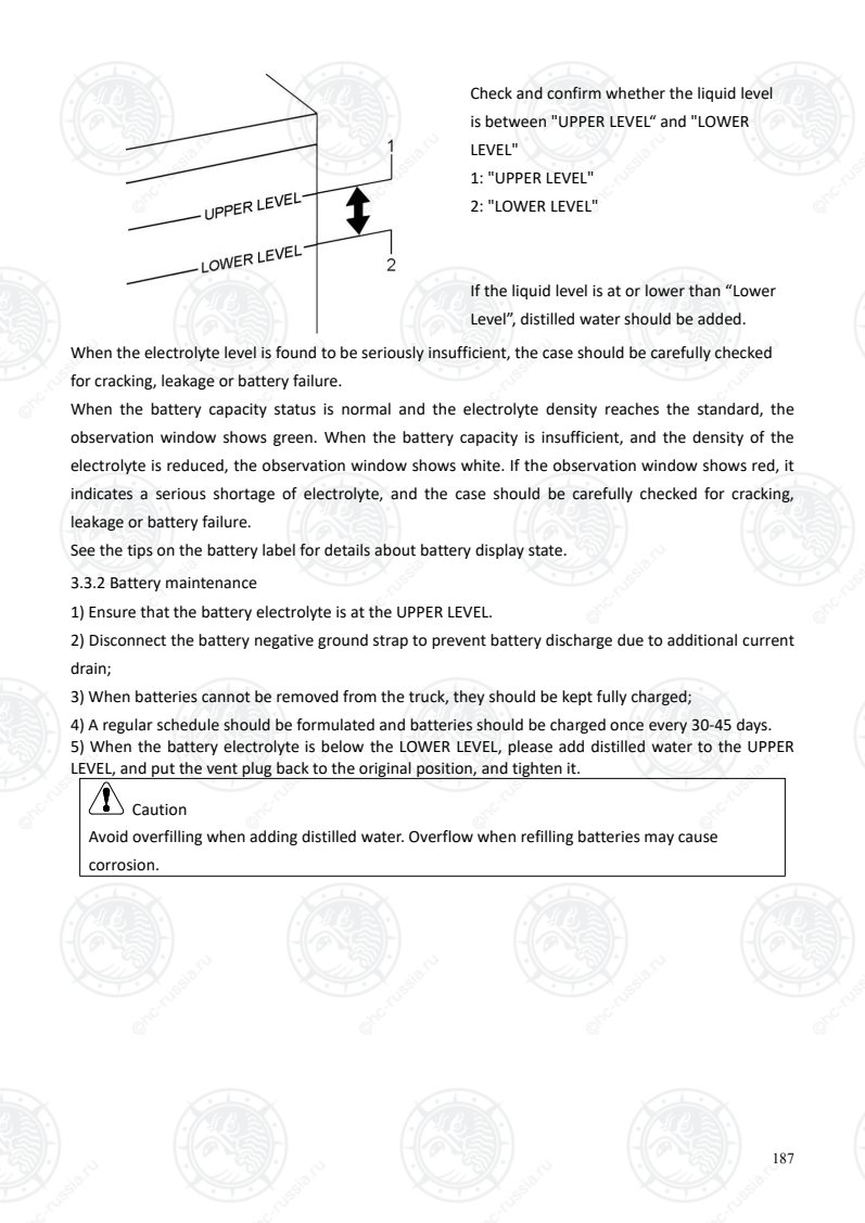
Страница 192
188
IV. Before refilling batteries
During recharging, the hydrogen produced by batteries is flammable and explosive. Therefore,
pay attention to the following matters before operation:
· If batteries that are still installed on the truck are recharged, the ground cable must be
disconnected.
· When connecting and disconnecting battery charger cables, the power switch on the charger
should be off.
Caution
·It is only safe to charge batteries in open areas. Do not charge batteries in a poorly ventilated
garage or enclosed room.
·Do not charge batteries when the engine is running. All attachments must be turned off.
V. Precautions for using batteries
Batteries can produce explosive gases, the electrolyte is corrosive, and batteries can generate enough
current to burn your skin. When handling batteries or working nearby them, you should observe the
following precautions:
Caution
·Wear safety goggles when working nearby batteries.
·Do not contact the battery terminal with tools to avoid sparks.
·Do not expose batteries to naked flames and sparks.
·When batteries are connected with electrical equipment, attention should be paid to the
correct connection of positive and negative electrodes to avoid fires.
·Do not place conductive items on batteries to avoid short circuits.
·Avoid splashing electrolyte on your eyes, skin, or clothing.
·Keep batteries away from children.
Emergency measures for electrolyte:
· If the electrolyte gets into your eyes,
You should rinse your eyes with clear water for at least 15min and see a doctor immediately. If
possible, you should continue to clean your eyes with a sponge or cloth that can absorb water on
the way to hospital.
· If the electrolyte spills onto your skin
you should clean the site thoroughly. If you feel burning or pain, you should see a doctor
immediately.
· If the electrolyte spills on your clothing
it can penetrate clothing and stick on your skin. You should take off your clothing immediately
and take the previously mentioned measures if necessary.
Оригинальная страница: таблицы и схемы
Страница 193
189
XV. Use, installation and safety rules for attachments
Hangcha selects attachments, such as the flat clamp, rotating clamp, roll clamp, string rod, sideshifter
and others in accordance with ISO2328 Fork Lift Trucks-Hook-on Type Fork Arms and Fork Carriers-
Mounting Dimensions.
Sifeshifter Fork Positioner Rotator Push-puller String rod
Round rod clamp Roll clamp Brick clamp Load bearing stabilizer Rotating fork
1. Use of attachments
(1) Become familiar with the relevant content on the nameplate of the forklift truck, read the relevant
operation manual carefully before use (especially the user manual and installation manual of the
professional accessory company), and be trained and qualified to operate the forklift truck
attachments.
(2) Fully understand the basic performance and operation methods of forklift attachments, especially
the allowable load, lift height, cargo size and the fitting range of attachments;
(3) When operating forklift truck attachments with multiple functions, such as side shift, clamping or
rotation, do not perform multiple operations at the same time. One action can be carried out only
after the other one is completed.
(4) Forklift trucks provided with attachments must not be driven when the cargo is at a high level;
when the cargo volume is too large do not drive the forklift truck forwards; when transporting cargo,
ensure that cargo is 300mm above the ground, and the mast is tilted backward;
(5) The weight of the cargo should not exceed the limit of the combined bearing capacity of the forklift
truck and attachments. Try not to load eccentrically at high cargo positions. Attachments with side
shift function can only be operated for a short time. Eccentric load is strictly limited to 100mm on the
left and right (the side shift amount for side shifters above 5 tons (including 5 tons)) is within the
range of ±150mm);
(6) Except for the driver's position which is protected by the overhead guard, it is strictly prohibited to
stand within 2 meters of the projection area under attachments and cargo to avoid injury.
(7) It is strictly prohibited to emergency brake forklift trucks with attachments when driving and it is
necessary to drive slowly with a load.
(8) Do not allow external forces to act on the truck when the attachment is working; it is forbidden to
Оригинальная страница: таблицы и схемы
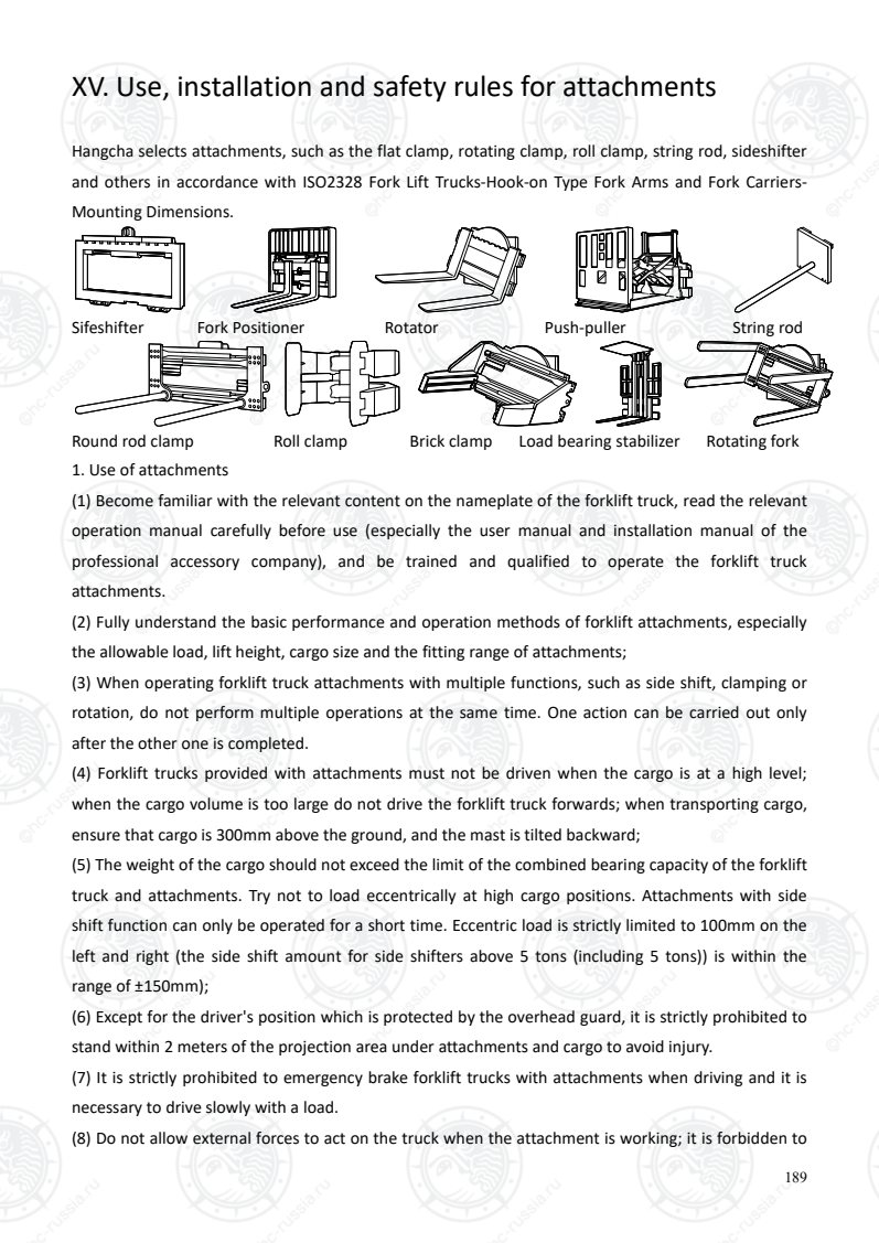
Страница 194
190
use the attachment for unsuitable purposes, and the normal working range of the attachment must
not be exceeded;
(9) Do not use attachments for unsuitable purposes, do not exceed the normal scope of work of
attachments;
(10) When attachments are faulty, they should not be used until the fault has been eliminated.
The following inspection and maintenance should be carried out frequently
(1) Check whether the spacing between the lower beams of the forks of the forklift truck and the
lower hooks of attachments conform to the requirements of the accessory manual.
(2) Check whether the upper hook is properly embedded in the groove of the fork arm carrier of the
forklift truck.
(3) The upper and lower sliding support surfaces should be lubricated with general lithium-based
grease for automotive use every 500 hours.
(4) Check fasteners for tightness.
(5) Regularly check whether hydraulic circuit connections are loose and whether the hose is damaged.
If it is damaged, it must not be used before repair.
(6) Regularly check whether the transmission or rotating elements of attachments are worn or stuck,
and replace them promptly if any damage or defect is found.
(7) In the case of dynamic loads, check whether the working elements of the attachments are normal,
whether the working pressure of the attachments is normal, and whether the attachments work
normally. If not, it is necessary to check the hydraulic circuit, find any leaking elements, and replace
the seals or the whole circuit.
Оригинальная страница: таблицы и схемы
Страница 195
191
2. Installation of attachments
Warning
1. Without the technical permission of the company, it is strictly prohibited to modify the safety
and performance of the forklift truck attachments.
2. The actual rated bearing capacity shall be the rated bearing capacity of the forklift truck, the
bearing capacity of attachments, or the overall bearing capacity of the complete truck, whichever
is the smallest. Generally speaking, the comprehensive bearing capacity of the complete truck is
the lowest of the three. “Bearing capacity of attachments” is a calculated value for the force
applied on attachments.
3. The installation and positioning should be reasonable, reliable and safe, to avoid attachments
sliding from side to side along the fork arm carrier of the forklift truck during use.
4. After the attachments are mounted, if there is a upper hook block, it should be embedded in
the notch of the upper beam, so that the offset between the center line of attachments and that
of the fork arm carrier is less than 50mm; otherwise, it will affect the lateral stability of the
forklift truck.
5. For attachments with a rotation function, (roll clamp, soft clamp, multi-purpose rigid arm
clamp, bucket clamp) after hanging and installation, stop blocks should be welded on both sides
of the joint between the upper beam of the fork arm carrier and the attachments to prevent
sliding when operating them;
6. When attachments with lower hook positioning are installed, the joint spacing between the
lower hook and the lower beam of the fork arm carrier should be adjusted appropriately.
Оригинальная страница: таблицы и схемы
Страница 196
192
XVI. OPS (Operator Presence Sensing) system instruction
OPS system (EPS based hydraulic trucks only)
The OPS (Operator Presence Sensing) system is mainly used for safety protection, that is, when the
operator is not in the correct driving position, the forklift cannot be driven and transported, thereby
reducing accidents caused by misuse.
Forklift truck shutdown conditions
When the driver leaves his/her seat or his/her safety belt is loose (if the safety belt protection switch
is provided) and the hand brake is not pulled up, the buzzer will sound an alarm.
Without the safety belt protection switch: When the driver sits back on the driver's seat properly or
pulls up the hand brake, the buzzer alarm will turn off.
With the safety belt protection switch: When the driver first sits back on the driver's seat properly and
fastens his/her safety belt or pulls up the hand brake, the buzzer alarm will turn off.
Forklift truck start conditions
1. Start
The forklift truck can be started normally when the driver sits on the driver's seat properly, fastens the
safety belt (if the safety belt protection switch is provided), or engages the hand brake, and pulls the
shift switch to the neutral position. If the shift switch is not pulled to the neutral position, the truck
cannot be started.
Warning
If the forklift truck is parked on a ramp, you must press the brake pedal to the bottom to start the
truck to prevent the truck from rolling back.
2. Forward and backward protection
When you are ready to drive the forklift truck after the engine has started, you can start the truck
normally by pulling the shift switch to forward gear 1 or reverse gear 1. If the shift switch is pulled to
forward gear 2 or backward gear 2 directly, the neutral indicator light will flash; if the truck cannot be
started, the shift switch should be returned to the neutral position to release protection.
When the driver leaves his/her seat or his/her safety belt is loose (if the safety belt protection switch
is provided) for more than 3s when the forklift truck is driving, the buzzer will sound an alarm, the
neutral indicator light will flash, the OPS indicator light will turn on, and the truck will be automatically
stopped.
When the driver sits on the driver's seat properly again, the buzzer alarm will turn off and the OPS
indicator light will turn off; when the shift switch is pulled to the neutral position, the flashing neutral
indicator light will constantly turn on; when the shift switch is pulled forward or backward, the forklift
truck will resume normal operation.
Caution
Some models are not equipped with an “ ”OPS indicator light on the instrument panel.
For the forklift trucks with seats provided with a safety belt protection switch, after the driver
first sits back on the driver's seat properly and fastens his/her safety belt, normal operation can
be conducted.
The neutral indicator light flashes: The shift switch is in the neutral position by default in the
program, and the driver is reminded about pulling to the neutral position.
Warning
If the OPS system is activated by accident when driving uphill, it will disconnect the driving
power, making the forklift truck roll backwards. In order to avoid accidents, the driver must sit on
the driver's seat properly when driving uphill.
Оригинальная страница: таблицы и схемы
Страница 197
193
3. Working device protection
When the driver leaves his/her seat or his/her safety belt is loose (if the safety belt protection switch
is provided) for more than 3s when operating, the buzzer will sound an alarm, the OPS indicator light
will turn on, and the handling operation will be automatically stopped. If the driver sits on the driver's
seat properly again, the handling operation will continue.
Caution
For the forklift trucks with seats provided with a safety belt protection switch, after the driver
first sits back on the driver's seat properly and fastens his/her safety belt, normal operation can
be conducted.
Tilt the lever and accessory lever to the initial positions before releasing protection.
OPS controller faults
In the event of the following conditions, the forklift truck should be stopped in a safe place and
Hangcha agency should be contacted for inspection.
a) When you are ready to start the forklift truck, and you pull the shift switch to forward gear 1 or
backward gear 1, the neutral indicator light flashes.
b) When you pull up the hand brake, the buzzer continues to sound an alarm.
c) When the shift switch is pulled to the neutral position, the neutral indicator light continues to
flash.
d) When the driver leaves his/her seat or his/her safety belt is loose (if the safety belt protection
switch is provided) for more than 3s, the buzzer does not sound an alarm, and the OPS indicator
light does not turn on.
e) When the driver sits on the driver's seat properly again, the buzzer continues to sound an alarm
and the OPS indicator light does not turn off.
Caution
Some models are not equipped with an “ ”OPS indicator light on the instrument panel.
Оригинальная страница: таблицы и схемы
Страница 198
194
XVII. Forklift daily check and maintenance sheet
Date Check and Maintenance Item Operator
Оригинальная страница: таблицы и схемы
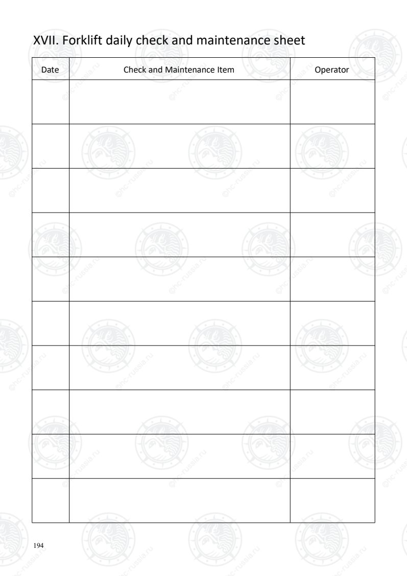
Страница 199
HANGCHA GROUP CO., LTD.
National customer service hotline: 400-884-7888
■ Address: No. 666, Xiangfu Road, Lin‘an District, Hangzhou City, Zhejiang Province, China
■ Tel: 0571-88926666 (headquarter) 85191117
■ Fax: 0571-85131772 ■ Postcode: 311305
■ Website: http://www.zjhc.cn ■ E-mail: sales@zjhc.cn
■ Address For: OVERSEAS USERS
■ Address: 666 Xiangfu Road, Lin'an,Hangzhou, Zhejiang, China
■ Fax: 0086-571-88926789 0086-571-88132890 ■ ZIP:311305
■ Web: http://www.hcforklift.com ■ E-mail: sales@hcforklift.com
Оригинальная страница: таблицы и схемы
Уточните документ по серийному номеру
Если исполнение машины отличается от указанного в руководстве, передайте фото её заводской таблички в сервис.